Abstract
Due to the medium and small damping characteristics of the hard coating compared with viscoelastic materials, the classical modal strain energy (CMSE) method cannot be applied to the prediction of damping characteristics of hard-coating composite structure directly. In this study, the CMSE method was modified in order to be suitable for this calculation, and then the damping optimization of the hard-coating thin plate was carried out. First, the solution formula of modified modal strain energy (MMSE) method was derived and the relevant calculation procedure was proposed. Then, based on the principle that depositing the hard coating on the locations where modal strain energy is higher, the damping optimization method and procedure were presented. Next, a cantilever thin plate coated with Mg-Al hard coating was taken as an example to demonstrate the solution of the modal damping parameters for the composite plate. Finally, the optimization of coating location was studied according to the proposed method for the cantilever thin plate, and the effect of the coating area on the damping characteristics of hard-coating plate was also discussed.
1. Introduction
Because hard coating has the advantages of high hardness, high-temperature resistance, and anti-corrosion, it has been widely used in aircraft, aerospace, vehicles, machine tools, and other fields [1,2,3]. The hard coating is usually prepared by air plasma spraying (APS) and electron beam-physical vapor deposition (EB-PVD) [4] and Stony’s approach is commonly used to check the characteristics of coating [5]. Recent studies have shown that the hard coating will contribute to the increase of structural damping and the decrease of resonant stress [6,7]. In other words, hard coating has the effect of vibration reduction.
The study of hard-coating damping design involves the preparation of hard-coating material, the testing of characteristic parameters, the dynamic modeling of hard-coating composite structure, and so on. Among them, the prediction of damping characteristics of hard-coating composite structure is a key content and the obtained results can provide references for the vibration control of thin shell structure. For the viscoelastic composite structure, the CMSE method [8,9] can accurately obtain the modal loss factors of composite structure with no need for calculating complex eigenvalues. The CMSE method has also been used to evaluate the functional dependence of damping on temperature and frequency for a coating beam structure [10]. In terms of calculating principles of the CMSE method, the internal damping of metal substrate is usually neglected, thus different complex stiffness matrices will be produced compared with the practical composite structure. This assumption is reasonable for the viscoelastic composite structure, because the loss factor of viscoelastic material is much larger than the internal damping of metal material, the change of the complex stiffness matrix is small and acceptable. However, the loss factor of hard coating is larger than that of metal but far less than that of viscoelastic material [11]. For this case, the CMSE method is no longer applicable for the prediction of the damping properties of hard-coating composite structure directly. In addition, the CMSE method generally only uses the real part of the complex stiffness matrix to calculate the eigenvectors of the composite structure, which is used to calculate the modal strain energy further. Because the imaginary part of complex stiffness matrix has certain contribution to the solution of these eigenvectors, this computation pattern can also introduce errors for the damping prediction of the composite structure [12].
Furthermore, during the hard-coating damping design, damping optimization also needs to be involved, that is, the hard coating should be coated on the proper locations of the structure to achieve the optimum damping effect. The optimization of coating location is extremely important. On one hand, compared with full coating, the strategy of partial coating can reduce treatment cost; on the other hand, it can minimize the change of the original structure and the increase of structural mass. Some literature [13,14,15,16] has proven that the resonant response or resonant stress of the structure can be effectively suppressed if the damping materials are coated on the locations where modal strain energy is higher. Therefore, damping optimization can be easily implemented with the reference of the distribution of modal strain energy. Then, to obtain the most favorable effect of vibration reduction, the key points of this optimal design lie in the accurate prediction of the damping parameters of hard-coating composite structure and the reasonable design of optimization procedure.
Considering the research status above, an MMSE method is developed in this study. It is relatively more suitable for predicting the damping characteristics of hard-coating composite structure, because the material damping of both metal substrate and the hard coating are contained and the imaginary part of the complex stiffness matrix is also considered. On the basis of this, the damping optimization of the composite structure is presented. The article is organized as follows. In Section 2, the solution formula of the MMSE method was derived and the relevant calculation procedure was proposed. In Section 3, based on the principle that depositing the hard coating on the locations where modal strain energy is higher, the damping optimization method and procedure were presented. In Section 4, a cantilever thin plate coated with Mg-Al hard coating was taken as an example to demonstrate solution of the modal damping parameters for the composite plate. In Section 5, the optimization of coating location was studied according to the proposed method for the cantilever thin plate, and the effect of the coating area on the damping characteristics of the hard-coating plate was also discussed. Some important conclusions were acquired from the study and they are listed in Conclusions.
2. MMSE Method for the Hard-Coating Composite Structure
2.1. Calculation Principle
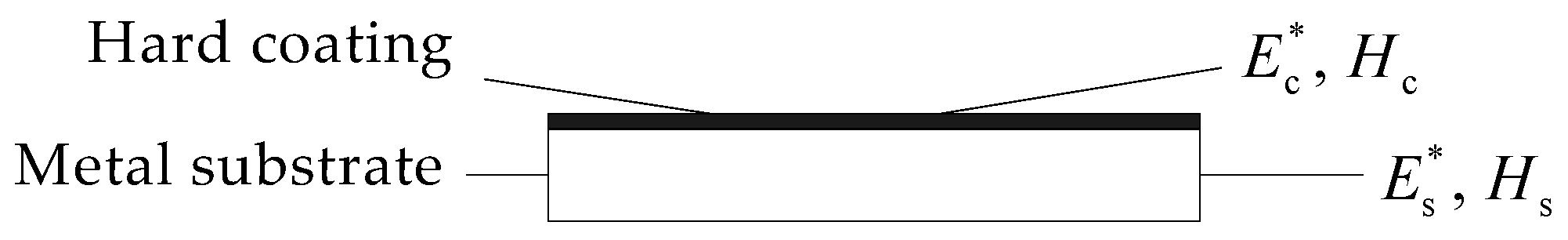
The schematic of a hard-coating composite structure is shown in Figure 1 and it consists of a hard-coating layer and a metal substrate. Symbols Hc, Hs, and Ec*, Es* are the thickness and the complex modulus of the hard coating and the metal substrate, respectively. Ec* and Es* can be expressed as
where, * represents a complex number, i = , and Ec, Es, ηc, ηs are the Young’s modulus and loss factor of the hard coating and the metal substrate, respectively.
Ec* = Ec (1 + iηc), Es* = Es (1 + iηs)

Figure 1.
Hard-coating damping composite structure.
Since the elastic modulus of the hard coating and the metal substrate are expressed by complex modulus, the finite element dynamic equation of the system in frequency domain becomes
where, M is the mass matrix of the composite structure, KR is the real part of the complex stiffness matrix, KI is the imaginary part of the complex stiffness matrix, F is the exciting force vector, and X is the displacement vector.
The real and imaginary parts of the complex stiffness matrix can be further expressed as
where, KRS, KRC and KIS, KIC represent the contributions of the metal substrate and the hard coating to the real and imaginary parts of the complex stiffness matrix, respectively.
For the CMSE method, usually, only the real part KR of the complex stiffness matrix is adopted to construct characteristic equation, which is used to solve the real mode and can be expressed as
where, ωr, φr are the r-th order natural frequency and modal shape, respectively. Further, the loss factor of composite structure can be solved using the obtained real modal shape and the solving equation is
where, ηr is the r-th order modal loss factor of composite structure. In addition, Equation (6) only considers the contribution of hard coating to the loss factor of the whole system, so the CMSE method cannot be used to predict the damping characteristics directly.
Then, the CMSE method is modified in this study. Two modified methods are proposed here and the main difference between the two methods is the pattern of constructing the characteristic equation. For the method of MMSE 1, the characteristic equation of solving mode shape can be written as
where, are the r-th order natural frequency and modal shape respectively obtained by the method of MMSE, and â is a modified coefficient which describes the contribution of the imaginary part of the complex stiffness matrix to the solution of mode shapes. The value of â can be calculated by [17]
where “trace ()” is a function to gain the trace of a matrix, namely, the sum of matrix diagonal elements.
Compared with the method of MMSE 1, the characteristic equation of the method of MMSE 2 is expressed as
It can be seen from Equation (9) that the modified coefficient, â is replaced by âr in the method of MMSE 2, which means that different order will have different modified coefficient. The solving formula for âr is shown as follows
It should be noted from the Equation (10) that the modal shape vector corresponding to the CMSE method (shown in Equation (5)) needs to be used during the solution of modified coefficient âr for the method of MMSE 2.
According to the MMSE method, the prediction formula of damping characteristics for the hard-coating composite structure can be finally determined as
It can be seen from the prediction formula that the loss factor of both the metal substrate and the hard coating are considered and the contribution of the imaginary part of the complex stiffness matrix to the modal shapes are also introduced. So the calculation accuracy of damping characteristics should be higher than the CMSE method.
2.2. Calculation Procedure of MMSE Method
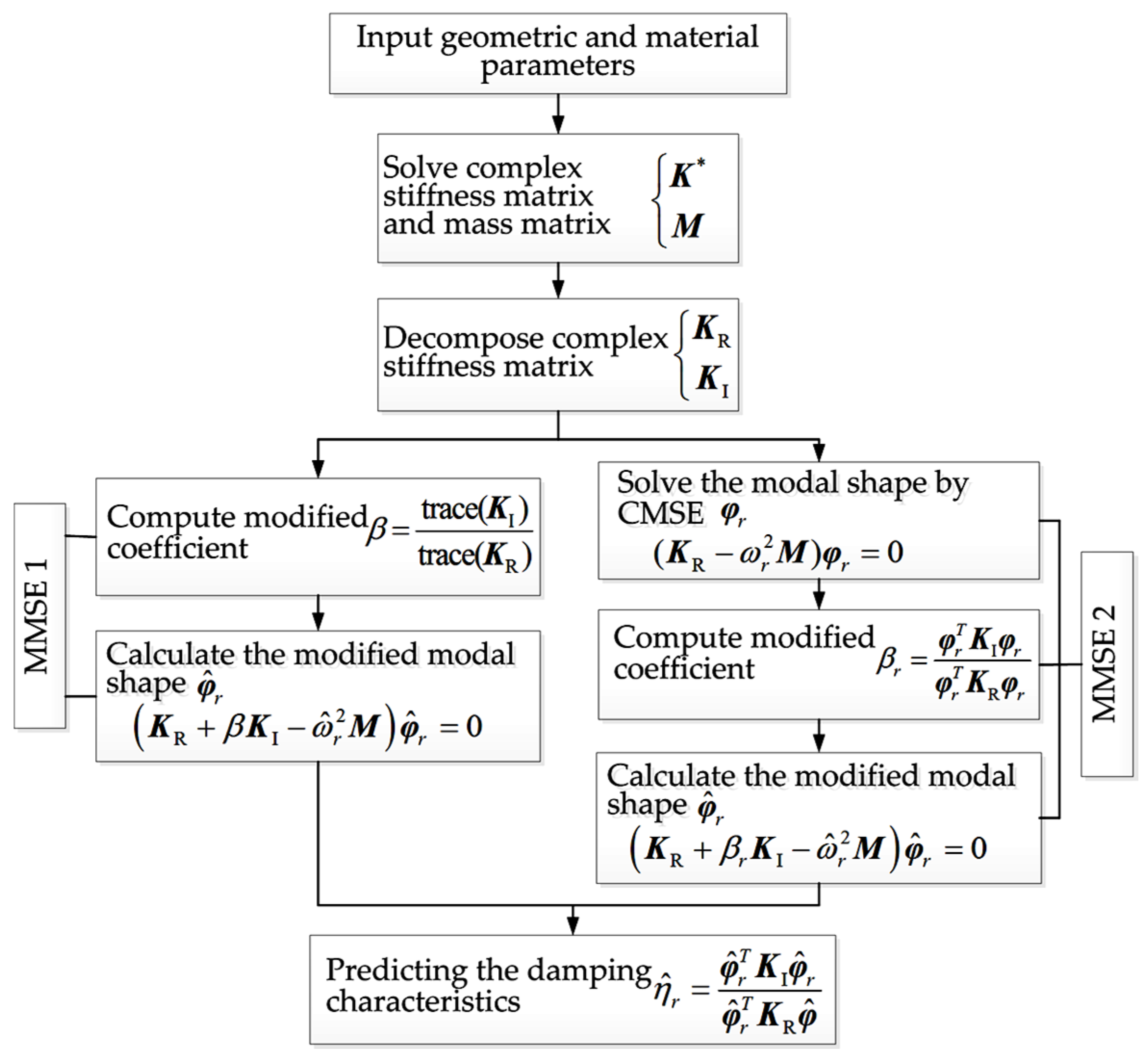
According to the aforementioned calculation principles, the calculation procedure of the two MMSE methods can be described according to Figure 2. It mainly includes five key steps: Solving the mass matrix and complex stiffness matrix, decomposing complex stiffness matrix, computing the modified coefficient, calculating the modified modal shape, and predicting the damping characteristics.
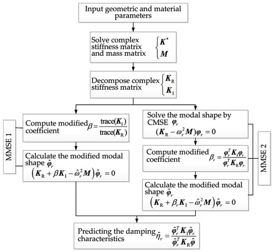
Figure 2.
The calculation procedure of MMSE method.
It should be noted that, for the method of MMSE 1, the modified coefficient â can be obtained by the direct utilization of real and imaginary parts of the complex stiffness matrix without using the calculation steps of CMSE method. However, for the method of MMSE 2, the CMSE method should be adopted to obtain the modal shape φr, and then âr—corresponding to different modal order—can be calculated. Obviously, the computational efficiency of MMSE 1 should be higher than that of MMSE 2. However, due to the fact that the influence of different modal order has been taken into account in MMSE 2, as a general rule, the computational accuracy of MMSE 2 should be higher than that of MMSE 1.
3. Damping Optimization of Hard-Coating Composite Structure by the MMSE Method
3.1. Damping Optimization Principle
The optimization for vibration reduction using hard coating is a comprehensive problem and the following constrained conditions should be considered, such as coating process, damping capacity, the influence of hard coating on the original performance, and the possibility of the peeling off of hard coating, etc. The objectives of optimization can be set as obtaining the optimal material parameters, coating thickness, coating location, and so on. In this study, only the optimization of coating location was considered, and the optimization study of material parameters and thickness of hard coating can be found in the author’s previous study [18].
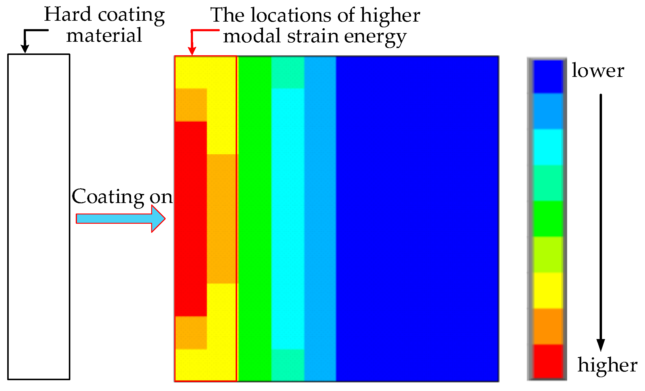
As mentioned in the introduction section, to obtain a better damping effect, the hard coating should be coated on the locations where modal strain energy is higher. This conclusion has been verified by the study of viscoelastic structure. For example, Kumar et al. [13], placed the viscoelastic damping material on the locations with higher modal strain energy for a curved plate and conducted the experiment to prove that this damping strategy can achieve excellent vibration reduction effect. Moreira et al. [14] did a similar study and they took the thin rectangular plate as research object, and also proved that placing the viscoelastic damping material on the locations with higher modal strain energy is most efficient for vibration reduction by experimentation. Masti [15] and Sainsbury [16] also proved the conclusion using numerical studies. Because both hard coating and the viscoelastic damping material can be characterized by complex modulus model, and also because both of them suppress the excessive vibration of the structure and dissipate energy by the material internal damping, the optimal principle of this study can be thought of as similar to the above description. A simple optimization schematic diagram for thin plate structure is shown in Figure 3. It is the distribution of the first order modal strain energy of a cantilever thin plate. In addition, it should be noted that the higher modal strain energy is a relative concept. Here, according to the distribution of modal strain energy, the area with high modal strain energy is defined as the area accounting for 20%–50% of the full structure, the modal strain energy of elements in this area is significantly higher than the elements in the remaining area.
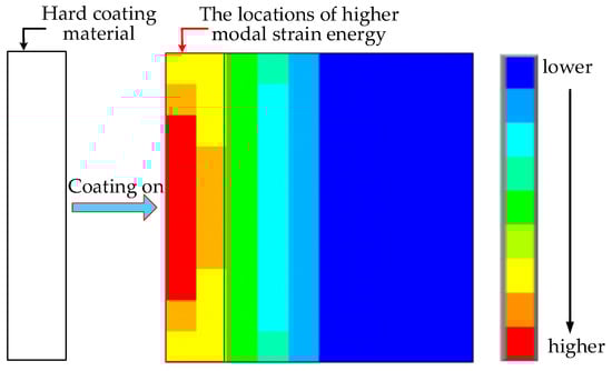
Figure 3.
A simple optimization schematic diagram for hard-coating thin plate structure.
Acquiring the modal strain energy distribution of the structure is the basis of implementing the optimization of coating location. To get the distribution, the modal strain energy of each element should be calculated firstly, the solving formula is
where, MSErj is the modal strain energy corresponding to the r-th order and the j-th element, , are the modal shape vector and stiffness matrix of the r-th order and the j-th element, respectively. This calculation shown in Equation (12) is for the metal substrate, thus the complex stiffness matrix was not used here. One can believe that it cannot produce big errors because the internal damping of metal substrate is small.
Then, the damping optimization method of coating locations can be established effectively and the optimal objective can be set for the single mode or multi modes. The proposed MMSE method can be used to evaluate the optimization effect. The detailed optimal procedure can be seen in the following discussion.
3.2. Optimization Procedure
In view of the fact that it is difficult to implement the MMSE method developed in this study by commercial FEM software, such as ANSYS, the optimization programs used here are in-house code developed by MATLAB and the version of MATLAB is MATLAB R2012a. The presented optimization procedure is shown in Figure 4. Here, the optimization of coating thickness and the material parameters are not contained and these parameters are set as constant.
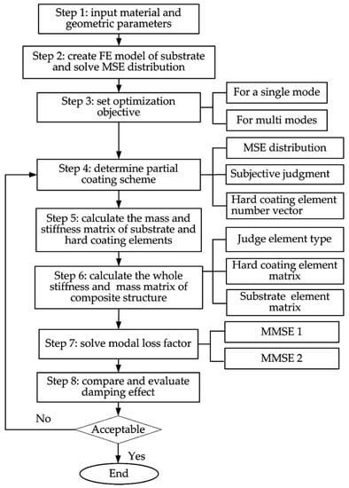
Figure 4.
The procedure of damping optimization based on MMSE.
Some key steps need to be explained and show as follows:
In Step 2, when meshing the structure and creating the finite element model, it is preferable to make all the elements have the same size. In this way, the mass and stiffness matrix of the elements need to be calculated only once and the computational efficiency will be dramatically improved.
In Step 3, the optimization objective can be set only for a single mode of the structure. This means that the hard coating has better vibration reduction effect only for the considered order. Also, the optimization objective can be set for multi modes, then, all the considered orders will have higher modal loss factors by implementing partial coating.
In Step 4, according to the distribution of modal strain energy and the optimization objective, the simulation of partial coating needs to be carried out, that is, placing the coating elements on the locations where the modal strain energy is higher. This step is done by subjective judgment and a coating element number vector will come into being after finishing this step.
In Step 6, before assembling the elements, it is necessary to judge the type of element by a condition discriminant function (ismember (..., ...)) firstly. If it is a coating element, the mass and stiffness matrices of hard-coating composite element should be introduced, otherwise, only considering the relevant matrices of substrate element. Then, in the light of the element number, all the elements are combined into the whole stiffness matrix and the whole mass matrix of the composite structure.
In Step 8, the damping effect of partial coating needs to be evaluated based on the optimization objective. The damping effect is usually compared with the full coating structure. If it is near or achieves the damping ability of full coating structure, the optimization can be considered acceptable. If not, return to Step 4 and reselect the coating locations.
4. Prediction of Damping Characteristics for a Cantilever Thin Plate Coated with Mg-Al Hard Coating
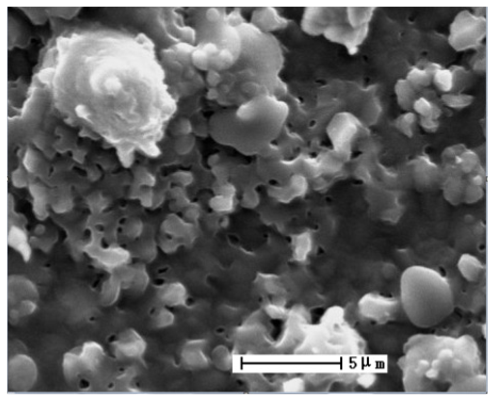
To verify the effectiveness of MMSE method, the damping characteristics of a cantilever titanium plate coated with Mg-Al hard coating are predicted by the proposed MMSE method in this section. It can be seen from the surface morphology of Mg-Al hard coating (shown in Figure 5), that there are many cracks and voids in the coating. The internal friction among coating particles will produce damping effects, thus Mg-Al coating can be used as a damping coating.
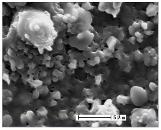
Figure 5.
Surface morphology of Mg-Al hard coating.
The geometry and material parameters of substrate and hard coating are listed in Table 1. One side of the cantilever plate is fully coated with Mg-Al hard coating. Among them, the Young’s modulus and loss factor of Mg-Al hard coating are obtained by experiment using vibration beam method [19] and the material parameters of the titanium plate are gotten from the handbook of metallic materials.

Table 1.
The geometry and material parameters of substrate and hard coating.
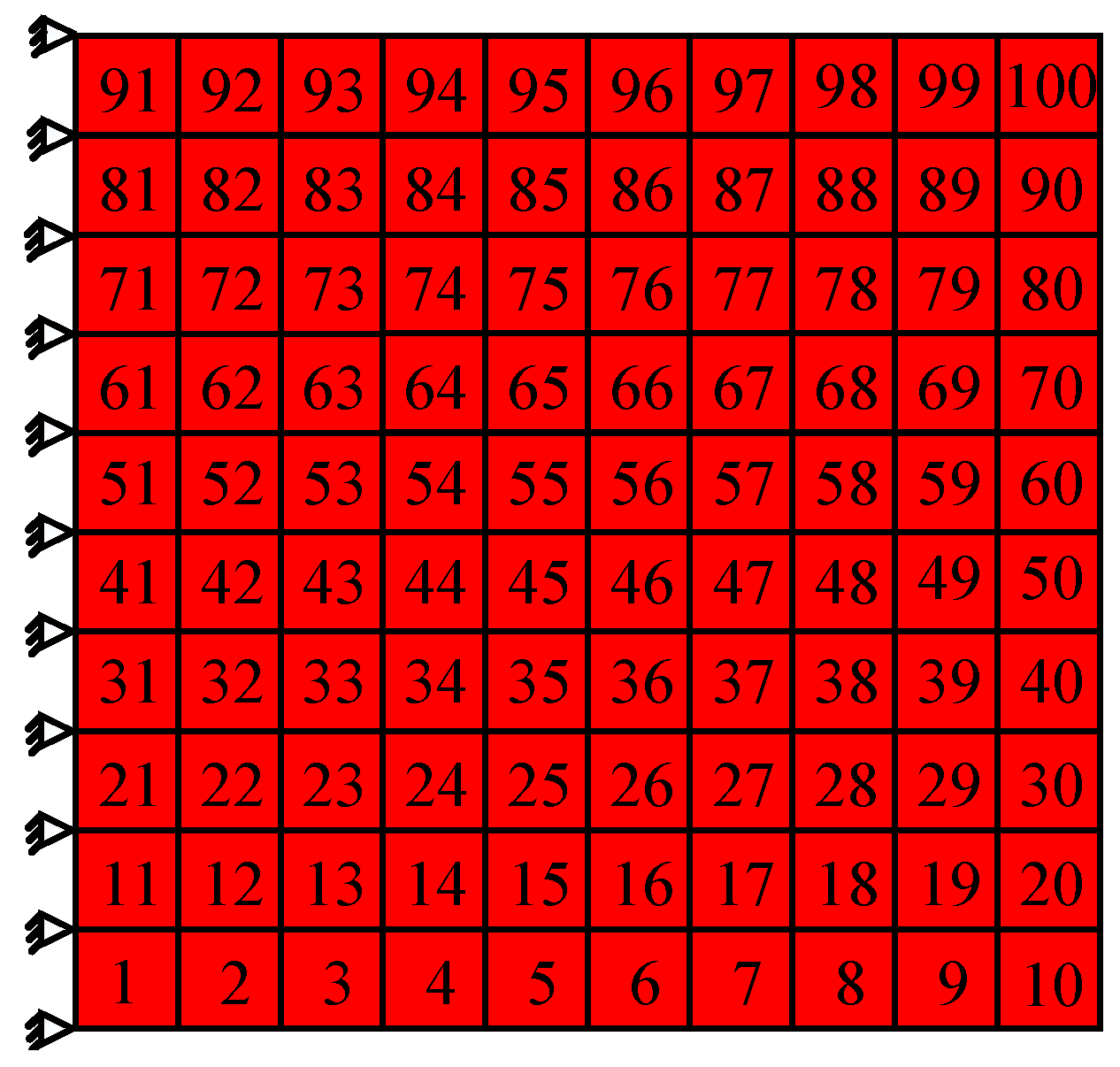
Here, to calculate the damping characteristics of the composite plate, the programs of CMSE, MMSE 1, and MMSE 2 are developed. The correctness of the developed programs is to be verified by ANSYS software, but only verification of CMSE method can be achieved by ANSYS. The finite element model is shown in Figure 6. The four-node plate element is adopted to simulate the hard-coating element. In the model, there are 100 elements and 121 nodes, respectively. The corresponding results are listed in Table 2.
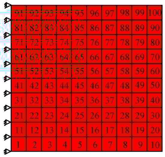
Figure 6.
The finite element model of hard-coating thin plate.
Table 2.
The obtained modal loss factor of hard-coating thin plate/10−3.
As seen in Table 2, for the calculation of modal loss factors by CMSE method, the results obtained from in-house code and ANSYS are almost consistent. However, the modal loss factor obtained by MMSE method is much different from the results obtained by CMSE method and the results of MMSE method are approximately six times that of CMSE method. Considering the uncertainties of hard-coating loss factors obtained by vibration beam method, the loss factor of hard coating listed in Table 1 is increased and decreased by 5%, respectively. Then, the damping characteristics of hard-coating plate are recalculated using the developed program and the results are listed in Table 3. It can be found from Table 3 that the values of modal loss factors of composite plate increase with the increase of the loss factor of hard coating and the results obtained by CMSE and MMSE method are obviously different.
Table 3.
Modal loss factors of composite plate corresponding to different loss factor of hard coating/10−3.
It can be known from the theoretical derivation in Section 2, for the MMSE method, the loss factor of both the metal substrate and hard coating are considered and the contribution of the imaginary part of the complex stiffness matrix to the modal shape is also introduced, so the MMSE method should be more accurate than the CMSE method. In addition, also it can be noted from Table 2 and Table 3 that the results obtained by the two kinds of MMSE methods are almost completely the same for the considered calculation accuracy, so either of the two MMSE methods can be chosen to optimize coating locations of the cantilever thin plate.
5. Damping Optimization of the Cantilever Thin Plate Partially Coated with Mg-Al Hard Coating
According to the optimization procedure described in Figure 4, the damping optimization is performed for the cantilever thin plate partially coated with Mg-Al hard coating in this section. The optimization objective is set for a single mode and multi modes, respectively. For the optimization calculation, only the method of MMSE 1 is adopted to predict the damping characteristics. Before implementing the damping optimization, the modal strain energy distribution of the cantilever thin plate should be determined first, and thus the modal strain energy distribution of the considered orders are also listed here.
5.1. Obtaining the Modal Strain Energy Distribution
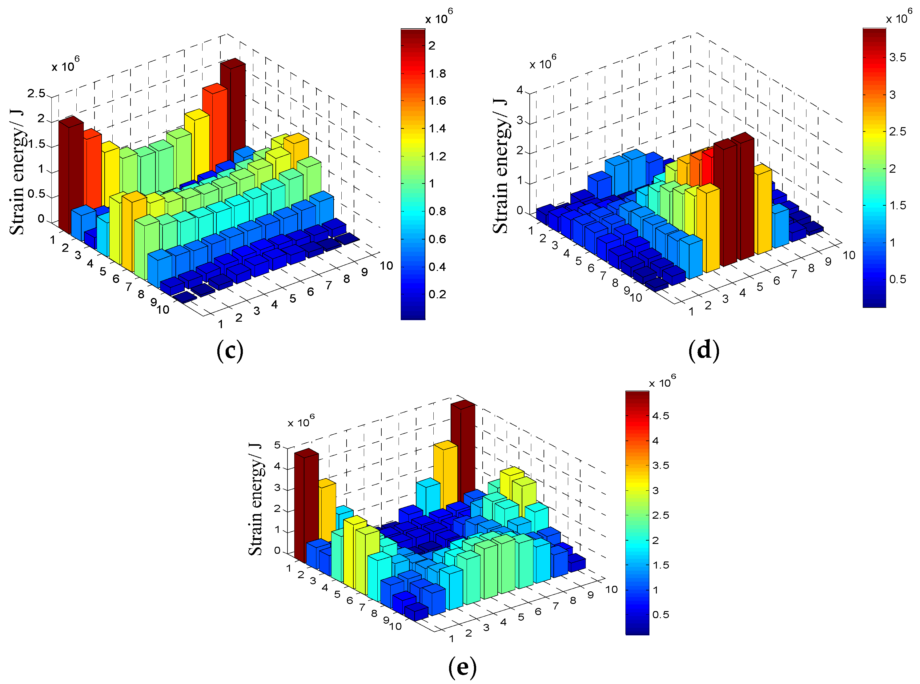
For the considered cantilever thin plate, the values of the first five natural frequencies are gotten by the modal analysis program existed in the in-house code and the relevant results are listed in Table 4. The corresponding modal strain energy distribution for each order is shown in Figure 7 and the 100 elements are disposed in a 10 × 10 matrix in the figure. It should be noted that the value of natural frequency of the structure is not required during the prediction of damping by modal strain energy method and the values listed here can be used as the reference for the damping optimization.
Table 4.
The first five natural frequencies of thin plate structure.
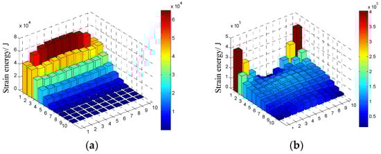

Figure 7.
The modal strain energy distribution of the first five orders of cantilever thin plate: (a) The first order; (b) the second order; (c) the third order; (d) the forth order; (e) the fifth order.
5.2. Damping Optimization for a Single Mode
Here, the first order and fourth order are taken as examples to describe the optimization of coating location for a single mode and only the optimization schemes are shown for the other orders. An optimization criterion can be used as the reference for conducting the single-mode optimization. It is that coating on elements for which accumulated modal strain energy is greater than 40% of the total modal strain energy of the structure.
5.2.1. Damping Optimization for the First Order
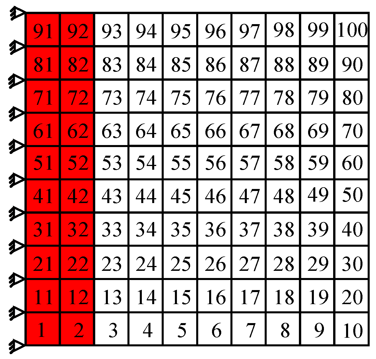
It can be seen in Figure 7a, for the first order, the higher modal strain energy of the cantilever thin plate appears on the edge of the fixed end. As a result, a total of 20 elements along the constraint end of the cantilever thin plate are chosen as the coating locations, which are obviously marked by the red shadow area in Figure 8. The calculation shows that cumulated modal strain energy of these coating elements is 59.54% of the total modal strain energy. For this partially coated thin plate, the first five modal loss factors are obtained by MMSE method and listed in Table 5. For comparison, the results corresponding to the full coating structure are also listed in Table 5.
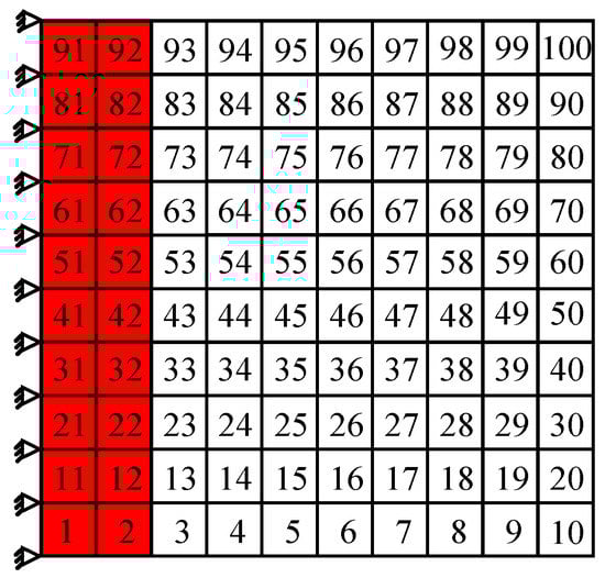
Figure 8.
The damping optimization scheme for the first order.
Table 5.
Comparison between the damping optimization results for the first order and the results corresponding to the full coating structure.
As shown in Table 5, when the damping optimization for the first order shown in Figure 8 is performed, the first order modal loss factor of cantilever thin plate is greater than those of the other orders, which means that this scheme can effectively suppress the first order resonance. In addition, compared with the results of full coating, the first order modal loss factor of the partial coating structure decreases only by 5.5%, but the coating area under this scheme decreases by 80%. These results indicate that the vibration reduction scheme shown in Figure 8 is feasible, even if only to suppress the first order resonance of cantilever thin plate.
5.2.2. Damping Optimization for the Fourth Order
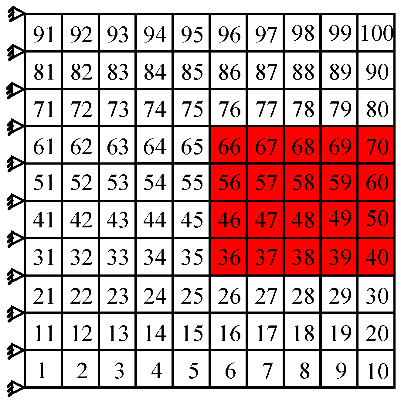
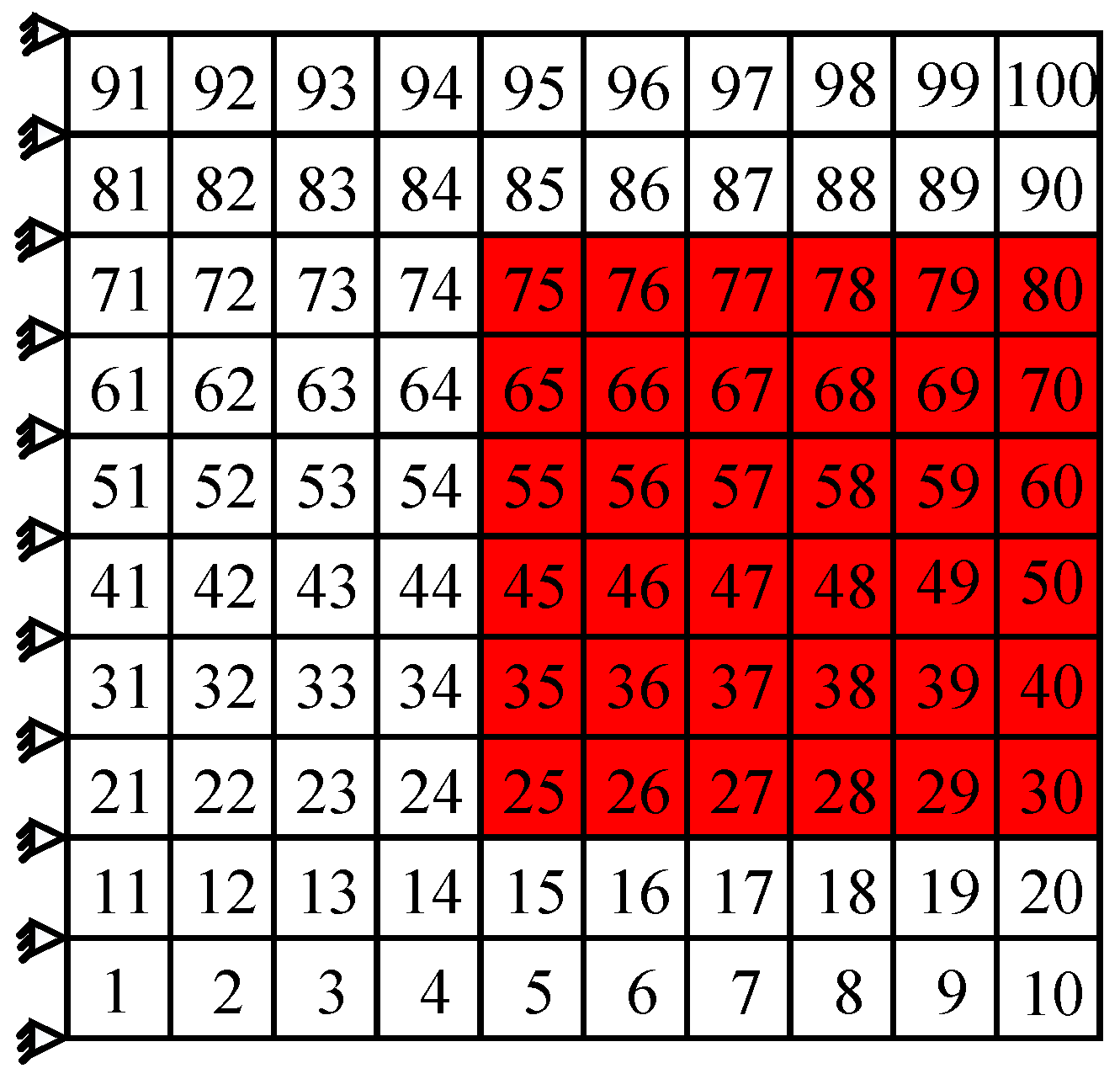
It can be seen in Figure 7d, for the fourth order, the higher modal strain energy of cantilever thin plate appears on the middle locations close to the free end. Then the damping optimization scheme for the fourth order can be achieved and shown in Figure 9. A total of 20 elements in the middle locations of the free end are chosen as coating elements which are described by red shadow shown in Figure 9. The calculation shows that cumulated modal strain energy of these coating elements is 49.92% of the total modal strain energy. Similarly, the first five modal loss factors corresponding to this damping optimization scheme are obtained by MMSE method and are listed in Table 6.
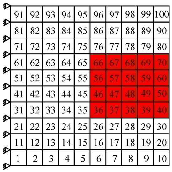
Figure 9.
The damping optimization scheme for the fourth order.
Table 6.
Comparison between the damping optimization results for the fourth order and the results corresponding to the full coating structure.
It can be noted from Table 6, when the damping optimization for the fourth order shown in Figure 9 is performed, that the fourth order modal loss factor of cantilever thin plate is greater than those of the other orders, which means that this scheme can effectively suppress the fourth order resonance. In addition, compared with the results of full coating, the fourth order modal loss factor of the partial coating structure decreases only by 6.3%, but the coating area under this scheme decreases by 80%. These results indicate that the vibration reduction scheme shown in Figure 9 is acceptable, if only to suppress the fourth order resonance of cantilever thin plate.
5.2.3. Damping Optimization for the Other Orders
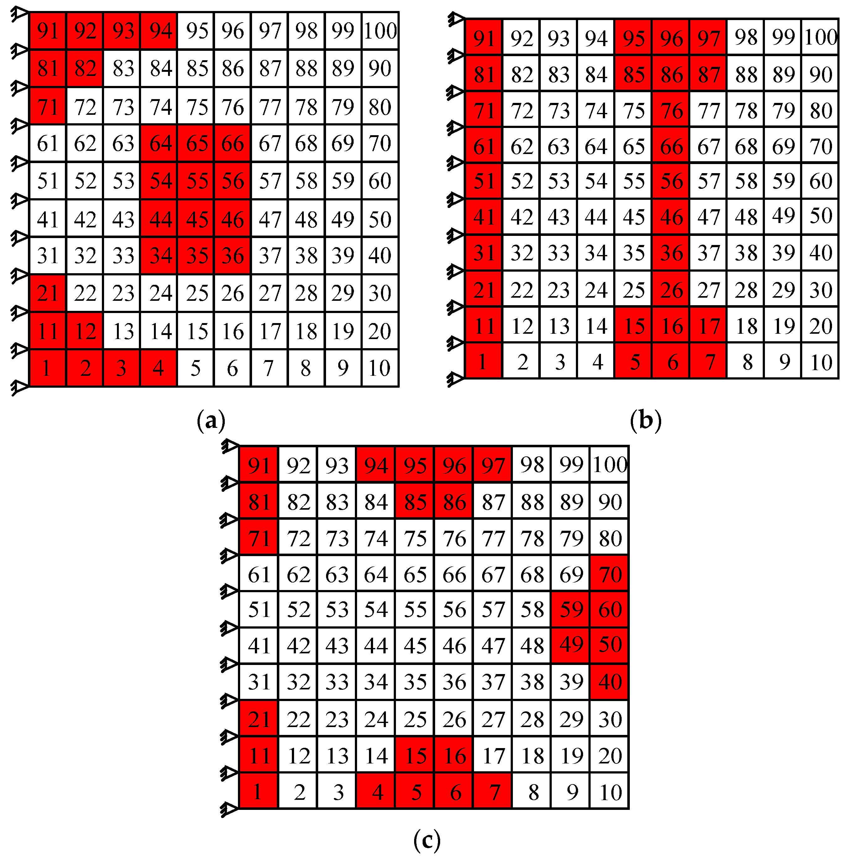
The optimizations for the second, third, and fifth orders have been performed, but the detailed contents were omitted here because the study process was almost consistent with the aforementioned orders. Only the damping optimization schemes are presented and shown in Figure 10.

Figure 10.
The damping optimization schemes for (a) the second order, (b) the third, and (c) fifth order.
5.3. Damping Optimization for Multi Modes
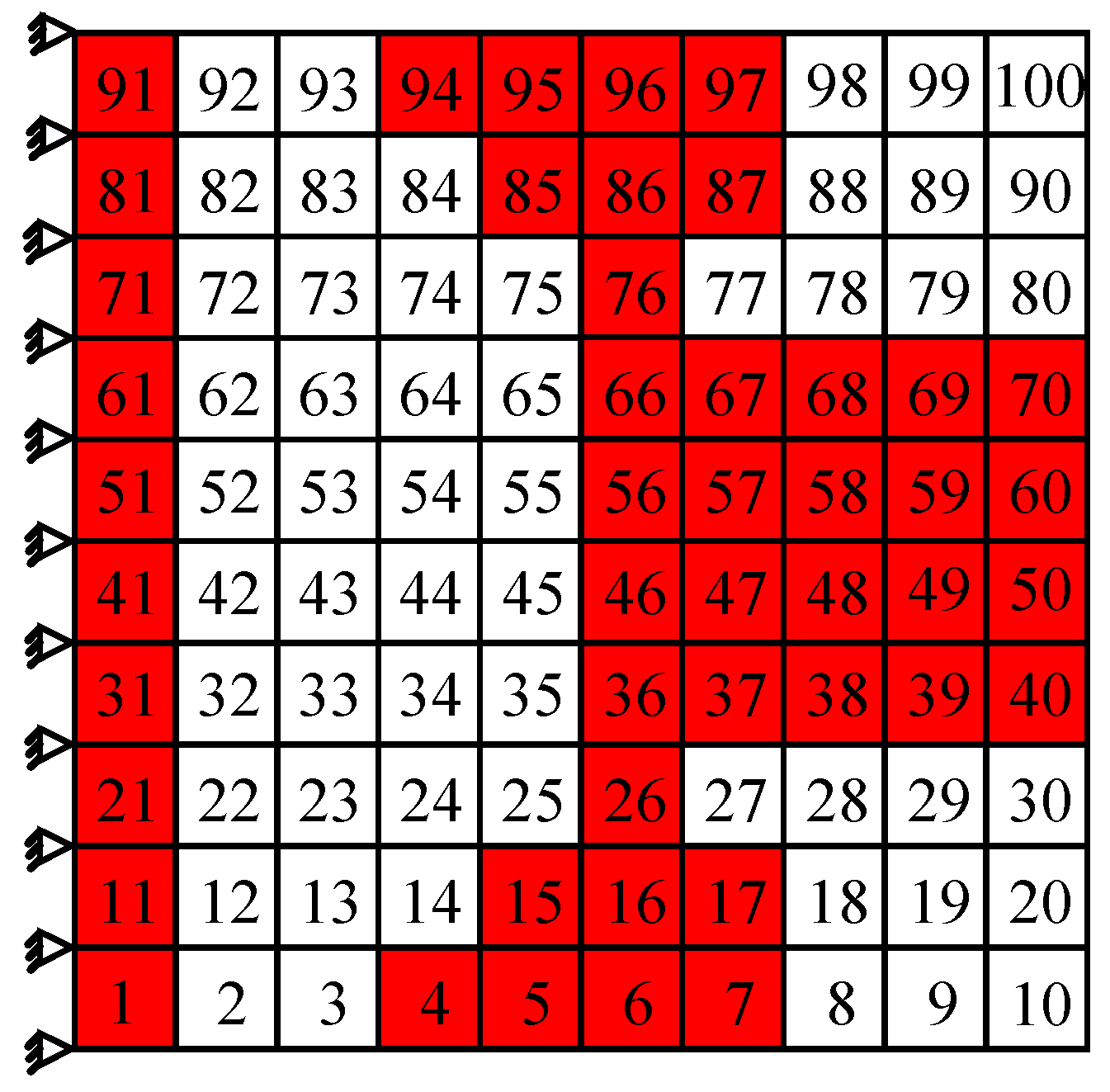
In the following, the damping optimization simultaneously for the third, fourth, and fifth order are taken as examples to demonstrate the damping optimization method for multi modes of the cantilever thin plate. Referring to the Table 4, it can be known that the third, fourth, and fifth order resonance frequencies are all in the frequency range of 1200–1800 Hz, which belongs to the higher frequency region, so the damping optimization simultaneously for the third, fourth, and fifth order has a certain engineering significance. When performing the damping optimization for multi modes, the location of higher modal strain energy corresponding to each order should be chosen as coating elements. It has been shown in Figure 7 that the locations of higher modal strain energy of the third and fifth orders appear on the two sides of the restrained end and locations of the fourth order are in the middle of the free end. As a result, the final optimization scheme is determined referring to the aforementioned higher modal strain energy distribution and shown in Figure 11. For this optimization scheme, a total of 46 elements are selected as coating elements marked by red shadow. Then, the first five modal loss factors are calculated by MMSE method and the results are listed in Table 7. For comparison, the single-mode optimization results for the relevant orders and the results corresponding to the full coating structure are all listed in Table 7.
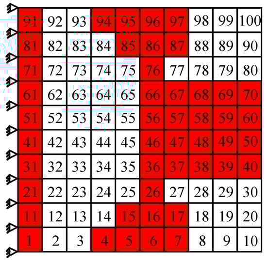
Figure 11.
The damping optimization scheme simultaneously for the third, fourth, and fifth order.
Table 7.
Comparison among the damping optimization results for a certain order, for multi orders, and the results corresponding to the full coating structure.
It can be found from Table 7 that the damping optimization scheme simultaneously for the third, fourth, and fifth order can make the damping values of the three orders closer to that of full coating structure. In the meantime, it can also make the first and second order have higher damping values. Although this kind of scheme uses more hard-coating material than the scheme for a certain order, the coating area still decreases by 54% compared with the full coating. Thus, during the damping design practice, if there are no special requirements (for example, just considering the suppression of the resonance of a certain order), the damping optimization for multi modes should be chosen preferentially, because this optimization objective can achieve a better vibration reduction effect.
5.4. The Influence of Coating Area on Damping Performance of Thin Plate
To better implement the damping optimization, the influence of hard coating area on damping performance of the whole composite plate is further discussed as follows. The hard coating is still coated on the location where the modal strain energy is higher, and then the influence of the changes of coating element number, which is corresponding to the coating area, on the damping performance of the composite plate is discussed. Here, the damping optimization scheme for the fourth order is chosen as an example to analyze the influence of coating area. In Section 5.2, a total of 20 elements in the middle of the free end are chosen to suppress the fourth order resonance of cantilever thin plate. Now the number of coating elements is increased to 36 and the relevant damping scheme is shown in Figure 12. Compared with the scheme shown in Figure 9, the coating area of this scheme increases by 80%. The first five modal loss factors are calculated by MMSE method and listed in Table 8. For comparison, the optimization results of the original scheme and the full coating structure are also listed in Table 8.
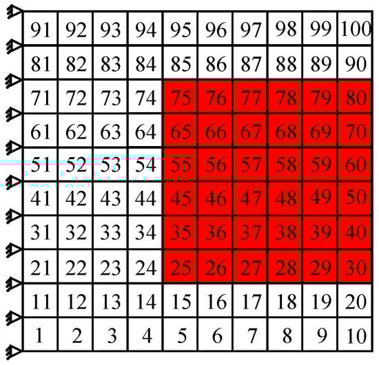
Figure 12.
The new damping optimization scheme for the fourth order (bigger coating area).
Table 8.
Comparison of modal loss factors for the new, original scheme and the full coating structure.
It can be noted from Table 8 that when the coating area increases by 80%, compared with the original scheme, the modal loss factors of partial coating plate increase, but the rate of increase is not very evident. Taking the fourth order modal loss factor as an example, the modal loss factor has increased only by 2.1%. Analogous results have been obtained, also, for the other orders. Therefore, an important conclusion can be drawn, and that is, the damping effect of the composite plate is not sensitive to the coating area. This conclusion is very favorable for vibration reduction using hard coating, which indicates that only choosing the zone with higher modal strain energy to deposit hard coating material, rather than paying close attention to the coating area, can bring a satisfactory damping effect.
6. Conclusions
This paper proposes the MMSE method to predict the damping characteristics of hard-coating composite structure. Then, the damping optimization method about coating location is studied. Some important conclusions are listed as follows:
- The thin plate coated with Mg-Al hard coating was chosen to demonstrate the developed MMSE method and the uncertainties of the loss factors of hard coating obtained by vibration beam method were also considered. All the calculation results show that the results obtained by CMSE and MMSE method are obviously different. Because more influencing factors are contained, the calculation accuracy of the MMSE method should be higher than that of the CMSE method.
- Compared with the full coating, a similar damping effect can be obtained by partial coating using the proposed optimization method. For example, in the study of the damping optimization for the first order and for the fourth order, under the premise of decreasing the coating area by 80%, the loss factor of the objective order decreased by only 5.5% and 6.3%, respectively.
- Compared with the damping optimization for a certain order, it can be found that if there are no special requirements (for example, just considering the suppression of the resonance of a certain order), the damping optimization for multi modes should be chosen preferentially in the actual damping design, because this optimization objective can achieve a better vibration reduction effect.
- The damping effect of composite structure is not sensitive to the coating area. This conclusion is very favorable for vibration reduction using hard coating, which indicates that only choosing the zone with higher modal strain energy to deposit hard coating material, rather than paying close attention to the coating area, can bring a satisfactory damping effect.
Acknowledgments
This project was supported by National Natural Science Foundation of China (Grant No. 51375079) and the Fundamental Research Funds for the Central Universities of China (Grant No. N140301001).
Author Contributions
Wei Sun and Rou Liu carried out the modeling and simulation of the work, Wei Sun analyzed the calculation results and wrote the paper.
Conflicts of Interest
The authors declare no conflict of interest.
References
- Limarga, A.M.; Duong, T.L.; Gregori, G.; Clarke, D.R. High-temperature vibration damping of thermal barrier coating materials. Surf. Coat. Technol. 2007, 202, 693–697. [Google Scholar] [CrossRef]
- Grzesik, W.; Zalisz, Z.; Nieslony, P. Friction and wear testing of multilayer coatings on carbidesubstrates for dry machining applications. Surf. Coat. Technol. 2002, 155, 37–45. [Google Scholar] [CrossRef]
- Fernández-Abia, A.I.; Barreiro, J.; de Lacalle, L.N.L.; Martínez-Pellitero, S. Behavior of austenitic stainless steels at high speed turning using specific force coefficients. Int. J. Adv. Manuf. Technol. 2012, 62, 505–515. [Google Scholar] [CrossRef]
- Patsias, S.; Tassini, N.; Lambrinou, K. Ceramic coatings: Effect of deposition method on damping and modulus of elasticity for yttria-stabilized zirconia. Mater. Sci. Eng. A 2006, 442, 504–508. [Google Scholar] [CrossRef]
- Rodríguez-Barrero, S.; Fernández-Larrinoa, J.; Azkona, I.; Lacalle, L.N.L.D.; Polvorosa, R. Enhanced Performance of Nanostructured Coatings for Drilling by Droplet Elimination. Mater. Manuf. Process. 2016, 31, 593–602. [Google Scholar] [CrossRef]
- Blackwell, C.; Palazotto, A.; George, T.J.; Cross, C.J. The evaluation of the damping characteristics of a hard coating on titanium. Shock Vib. 2007, 14, 37–51. [Google Scholar] [CrossRef]
- Ivancic, F.; Palazotto, A. Experimental considerations for determining the damping coefficients of hard coatings. J. Aerosp. Eng. 2005, 18, 8–17. [Google Scholar] [CrossRef]
- Johnson, C.D.; Kienholz, D.A. Finite element prediction of damping in structures with constrained viscoelastic layers. AIAA J. 1982, 20, 1284–1290. [Google Scholar]
- Hwang, S.J.; Gibson, R.F. The use of strain energy-based finite element techniques in the analysis of various aspects of damping of composite materials and structures. J. Compos. Mater. 1992, 26, 2585–2605. [Google Scholar] [CrossRef]
- Casadei, F.; Bertoldi, K.; Clarke, D.R. Finite element study of multi-modal vibration damping for thermal barrier coating applications. Comput. Mater. Sci. 2013, 79, 908–917. [Google Scholar] [CrossRef]
- Patsias, S.; Saxton, C.; Shipton, M. Hard damping coatings: An experimental procedure for extraction of damping characteristics and modulus of elasticity. Mater. Sci. Eng. 2004, 370, 412–416. [Google Scholar] [CrossRef]
- Hu, B.H.; Dokainish, M.A.; Mansour, W.M. A modified MSE method for viscoelastic systems: A weighted stiffness matrix approach. J. Vib. Acoust. 1995, 117, 226–2231. [Google Scholar] [CrossRef]
- Kumar, N.; Singh, S.P. Experimental study on vibration and damping of curved panel treated with constrained viscoelastic layer. Compos. Struct. 2010, 9, 233–243. [Google Scholar] [CrossRef]
- Moreira, R.A.S.; Rodrigues, J.D. Partial constrained viscoelastic damping treatment of structures: A modal strain energy approach. Int. J. Struct. Stab. Dyn. 2006, 6, 397–411. [Google Scholar] [CrossRef]
- Masti, R.S.; Sainsbury, M.G. Vibration damping of cylindrical shells partially coated with a constrained viscoelastic treatment having a standoff layer. Thin-Walled Struct. 2005, 43, 1355–1379. [Google Scholar] [CrossRef]
- Sainsbury, M.G.; Masti, R.S. Vibration damping of cylindrical shells using strain-energy-based distribution of an add-on viscoelastic treatment. Finite Elements Anal. Des. 2007, 43, 175–192. [Google Scholar] [CrossRef]
- Kung, S.W.; Singh, R. Complex eigensolutions of rectangular plates with damping patche. J. Sound Vib. 1998, 216, 1–28. [Google Scholar] [CrossRef]
- Sun, W.; Han, Q.; Qi, F. Optimal design of damping capacity for hard-coating thin plate. Adv. Vib. Eng. 2013, 12, 179–192. [Google Scholar]
- E756-04 Standard Test Method for Measuring Vibration-Damping Properties of Materials; American Society for Testing and Materials: New York, NY, USA, 2004.


© 2017 by the authors. Licensee MDPI, Basel, Switzerland. This article is an open access article distributed under the terms and conditions of the Creative Commons Attribution (CC BY) license ( http://creativecommons.org/licenses/by/4.0/).