Abstract
The interfacial behavior between lattice reinforcement and aluminum matrix plays an important role in determining the mechanical and tribological properties of lattice-reinforced aluminum matrix composites. In this study, 316L lattices with different aspect ratios were prepared by laser powder bed elting (LPBF) technology, and LY12 aluminum alloy was infiltrated under vacuum conditions. The effects of lattice aspect ratio on the interfacial reaction, microstructure, hardness, compressive strength, and wear resistance of the composites were systematically studied. First-principles calculations show that FeAl2 and FeAl3 intermetallic compounds are preferentially formed at the interface, showing good thermodynamic stability and mechanical properties. The microstructure analysis shows that the increase in aspect ratio promotes the formation of coarse FeAl3 phase and network AlCu, while a too-large aspect ratio leads to the instability of microstructure and the generation of microcracks. When the lattice constant is 10 mm and the diameter of the support is 1 mm (BCC-10-1), the composite material has the best wear resistance, and the specific wear rate is 3.07 × 10⁻⁴ mm3/(N·m). These findings provide valuable insights into the design of high-performance lattice-reinforced aluminum matrix composites with customized interface properties.
1. Introduction
In recent years, aluminum matrix composites have received extensive attention due to their excellent mechanical properties, good corrosion resistance, and high thermal stability, and have shown broad application prospects in aerospace, automotive, construction, and electronics [1,2,3,4]. Such materials usually improve their strength and stiffness by introducing reinforcing phases such as ceramic particles or fibers. However, traditional ceramic reinforcements often lead to a significant decrease in the ductility of the aluminum matrix and weak interface bonding with the matrix, which is prone to interfacial debonding under load. In addition, the difference in thermal expansion coefficient between ceramics and aluminum will cause internal residual stress, which in turn affects the reliability of the material [1]. At present, the demand for lightweight is increasingly urgent, and achieving excellent mechanical and physical properties at low weight has become a common goal in related fields.
In order to overcome the above limitations, interpenetrating phase composites have attracted attention. It is characterized by the formation of a three-dimensional topological interconnection structure between multiphases. Each constituent phase can be evenly distributed and wrapped to each other, thereby synergistically improving the overall performance. The structure can effectively inhibit crack propagation and significantly improve the toughness, strength, and energy absorption capacity of the material. Among them, metal matrix composites based on lattice-reinforced structures have been widely studied because of their continuously adjustable topological configuration and easy customization of performance [5,6,7,8]. With the development of additive manufacturing technology, especially the development of laser powder bed fusion (LPBF) technology, the precision manufacturing of complex lattices has become a reality, which has greatly promoted the development of a new generation of engineering components with customized mechanical properties [9,10,11,12,13,14]. The lattice-reinforced aluminum matrix composites prepared based on this technology have become the current research hotspot by using the topological continuous distribution of the reinforcing phase. As a reinforcement, stainless steel lattice has the advantages of high specific stiffness, strong designability, good energy absorption capacity, and low cost. By adjusting the geometric parameters such as cell type and relative density, the targeted regulation of mechanical properties can be achieved, which has important application potential [15,16,17].
In this context, the combination of additive manufacturing and melt infiltration technology provides an effective way to prepare high-performance bimetallic composites. Mirzababaei et al. [18] prepared a 316L-Cu composite system by LPBF, which significantly improved the thermal conductivity of the composite. This technology has become an important solution for the manufacture of advanced bimetallic composite materials. Statnik et al. [19] carried out systematic research on 3D-printed bronze/stainless steel bimetallic joints. The results show that the ductility and strength of the region near the interface are slightly lower than those of single metal materials but still show good ductility and acceptable strength. In addition, the 316L stainless steel and C18400 copper alloy bimetallic laminated composites prepared by LPBF also achieved good metallurgical bonding between the two metals. The above methods show great potential in the preparation of bimetallic composites, but their production efficiency still needs to be improved, which poses a certain challenge for large-scale applications.
Currently, the method of melt infiltration of 3D-printed preforms is often used for manufacturing metal matrix composites. Pawlowski et al. [20] proposed a two-step process route for manufacturing interpenetrating phase composites, preparing A356/316L interpenetrating phase composites by infiltrating additively manufactured 316L lattices with molten A356. First, LPBF technology was used to fabricate the 316L stainless steel lattice structure as the reinforcement phase. Die-casting technology was then employed to inject molten aluminum into the mesh structure of the 316L stainless steel reinforcement, ultimately forming the aluminum matrix composite. This two-step process can enhance both the thermal stability of the material and the interfacial bonding strength of the composite [21]. Subsequently, Poole et al. [22] successfully prepared composites with a 316L stainless steel skeleton and an A356 aluminum alloy matrix by combining Selective Laser Melting (SLM) and centrifugal casting. Research showed that this material performed significantly better than traditional homogeneous targets under impact loading conditions. On the other hand, the team of Moustafa [23], from the perspective of thermophysical properties, analyzed the thermal conductivity of 316L lattice/aluminum composites using both experimental and simulation methods. They found that pores existing at the composite interface severely hindered heat flow transfer, thus critically impacting the overall thermal conductivity.
Although a large number of studies have confirmed that stainless steel reinforcement can significantly improve the mechanical properties of aluminum matrix composites, the related interface behavior and its influence have not been systematically studied. Pawłowski et al. [20] found that intermetallic compounds are formed at the interface between the stainless steel lattice reinforcement and the aluminum matrix, which affects the plasticity and ductility of the composite. Ghasri-Khouzani et al. [24] reported that stress transfer failure occurred between the reinforcement and the matrix during the loading process due to poor interface bonding. The Hamada team [25] tried to use pre-stirring technology to improve wettability, but there is still a phenomenon of incomplete interface bonding. This is mainly due to the oxide layer formed on the surface of stainless steel at high temperature, which hinders the effective alloying reaction between aluminum and steel [26]. In order to avoid the formation of harmful interfacial compounds, researchers have carried out many explorations. Wang et al. [27] combined LPBF and vacuum infiltration process to prepare 316L lattice-reinforced aluminum matrix composites with continuous interface and systematically studied the effect of infiltration temperature on interface evolution and properties. The results show that excellent mechanical properties and wear resistance can be obtained by the dual reinforcement of lattice structure and hard intermetallic compound layer.
Therefore, the hybrid manufacturing strategy combining traditional process and additive manufacturing is regarded as a feasible solution. For example, traditional technologies such as powder metallurgy and pressure infiltration can be combined with LPBF to prepare complex three-dimensional structural reinforcements, thus promoting the development of high-performance composites. However, the current systematic research through such specific process routes is still insufficient, and its comprehensive performance data and strengthening mechanism need to be further explored. The existing research has laid a foundation for the preparation of high-performance lattice-reinforced aluminum matrix composites. However, most of these works focus on specific fixed lattice configurations, mainly focusing on the influence of process parameters or material systems [20,28]. However, a key issue has been neglected: how do the core geometric parameters of the lattice itself, especially the ‘aspect ratio‘ that determines the structural stiffness, seepage path, and specific surface area, systematically affect the melt seepage, interfacial reaction, and final performance. The length–diameter ratio directly controls the contact time and reaction area between the molten aluminum and the reinforcing phase, and clarifying its influence law is the fundamental premise for realizing the customizable design of composite properties.
Therefore, in this study, 316L lattice-reinforced 2024 aluminum matrix composites with different aspect ratios were prepared by LPBF and vacuum infiltration technology. In this study, ‘aspect ratio’ (defined as the ratio of unit size to pillar diameter) was used as a key design variable to systematically explore its influence on the interfacial reaction, microstructure, compression, and wear resistance of composite materials, which provided theoretical and experimental basis for the design of lattice composite materials for specific requirements such as bearing or wear resistance.
It is of great significance to clarify the influence law of length–diameter ratio for optimizing the basic properties of composite materials and guiding their engineering application and process amplification. In this study, the idea of coordinating material strength, toughness, and wear resistance through geometric design provides a design basis for the development of lightweight impact-resistant or wear-resistant components required in aerospace, transportation, and other fields. At the same time, the ‘LPBF manufacturing lattice preform + vacuum infiltration’ route adopted in this study still faces several scalability challenges when moving towards large-scale applications, such as the uniform filling of melts in large-scale components, the control of interfacial reaction consistency, and the efficiency and cost of the two-step process. These challenges point to the key research directions required to move from laboratory optimization to engineering applications.
2. Experimental Procedure
2.1. Fabrication 316L Lattice Structure via LPBF
The ‘length-diameter ratio’ in this study is defined as the ratio of the effective length of the lattice member to its diameter, which is the core design variable. All samples in this paper are uniformly named BCC-X-Y, where BCC represents the body-centered cubic lattice, X represents the diagonal length of the unit cell (mm), and Y represents the diameter of the rod (mm). In this study, as shown in Figure 1, lattice structures with different aspect ratios are designed, and the specific parameter settings have clear physical directivity: small size combinations (such as BCC-5-0.5) are used to approximate the filling limit of melt in fine and tortuous channels; the large-size-thin-pillar combination (such as BCC-10-0.5) is used to explore the critical behavior of structural instability at high temperature. The series with increased pillar diameter (BCC-10-1 to BCC-10-2) are used to systematically evaluate the effect of structural rigidity improvement on suppressing instability and ensuring the integrity of infiltration. The lattice structure was prepared by a commercial LPBF system under nitrogen protection using pre-dried 316L stainless steel powder (composition is shown in Table 1). The 3D printing parameters were as follows: laser power 380 W, spot diameter 70 μm, scanning spacing 70 μm, layer thickness 20 μm, scanning speed 2000 mm/s. The stripe scanning strategy was used for printing, and the scanning direction of each layer was rotated by 45°. Before printing, the oxygen content of the forming chamber was controlled to ≤0% by a dynamic gas exchange system. In addition, the online process monitoring system is used to screen the samples in the manufacturing process, and only the structure without abnormal thermal signal alarm and macroscopic inspection without deformation in the whole process is selected for subsequent infiltration experiments, so as to ensure the geometric consistency of the reinforcement. Through the above strategy, the thin-walled lattice reinforcement with a BCC topological configuration was prepared and then randomly selected. The rod diameter and unit cell size were measured by an optical microscope and a scanning electron microscope. The average deviation of rod diameter was within ±5%, and the deviation of unit cell size was within ±2% [29].

Figure 1.
Body-centered cubic lattice structures with different aspect ratios: (a) BCC-5-0.5; (b) BCC-6.6-0.5; (c) BCC-10-0.5; (d) BCC-10-1; (e) BCC-10-1.5; (f) BCC-10-2.

Table 1.
Chemical composition of raw materials (wt.%).
2.2. Preparation of 316L Lattice/Al Composites via Vacuum Infiltration
The preparation process is shown in Figure 2, and the specific process is as follows. For the lattice configuration of each geometric parameter, three complete infiltration preparation processes are performed independently to ensure the reliability of the process and results. Firstly, the sample preparation was carried out. The 316L lattice skeleton used in the experiment was prepared by LPBF technology, and no surface coating or chemical activation treatment was performed before infiltration. Subsequently, the lattice skeleton was placed in a crucible, and an aluminum rod with a diameter and height of 15 mm was stacked directly above it. After the assembly is completed, the crucible is transferred to the uniform temperature zone of the vertical tube furnace, and the inner wall of the furnace is pre-lined with graphite paper. Then, the atmosphere control was carried out, the furnace chamber was vacuumized to 10-1 Pa, and then high-purity argon with purity of 99.999% was recharged as the protective atmosphere. After that, heating and infiltration began: heating to 850 °C at a heating rate of 10 °C/min and holding at this temperature for 1 h. During this process, the aluminum rod melted, and the molten aluminum infiltrated and filled the gap space of the lattice skeleton by its own gravity. Finally, the heating is stopped, and the sample is cooled in the furnace and completely solidified.
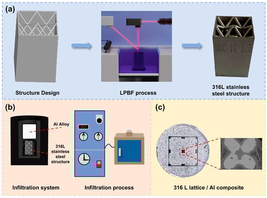
Figure 2.
Fabrication process flow chart of the aluminum matrix composites: (a) LPBF process and the 316L lattice reinforcement prepared by LPBF; (b) infiltration system; (c) 316L lattice-reinforced Al matrix composites prepared by infiltration.
2.3. Experimental Methods
To elucidate the interfacial reaction mechanism during the infiltration of molten aluminum into the stainless steel lattice, first-principles calculations were performed to investigate the potential intermetallic compounds (IMCs) that could form. The relevant calculation parameters are briefly described as follows. Based on the density functional theory (DFT), the calculations were conducted using the CASTEP module. The Perdew–Burke–Ernzerhof (PBE) method within the generalized gradient approximation was employed to treat the electron exchange-correlation energy. The stability, mechanical properties, and behavior of key IMCs at the interface were analyzed based on the systematic calculation results, providing a theoretical basis for optimizing the design of the Al/stainless steel composite interface. Firstly, a cylindrical specimen with a diameter of 40 mm and a height of 10 mm was cut by wire electrical discharge machining. Subsequently, the samples were ground step by step using 240 to 2000 mesh SiC sandpaper, and then finely polished with 1.5 μm diamond polishing paste and 0.05 μm silica colloidal suspension on a polishing pad covered with flannelette polishing cloth at a speed of 800 rpm to obtain a scratch-free mirror. All steps were ultrasonically cleaned with anhydrous ethanol and dried with cold air. Finally, the polished surface was etched with Keller reagent (2.5% HNO3, 1.5% HCl, 1.0% HF, residual distilled water) for 15–20 s and then observed under an optical microscope (OM). The phase identification was carried out by D8 advance X-ray diffractometer (XRD, Bruker, Karlsruhe, Germany). The microstructure and morphology of the hard phase were observed by JEOL SM-6360LV field emission scanning electron microscope (SEM, Tokyo, Japan). The distribution of alloying elements was analyzed by FALCON-60S energy dispersive spectrometer (EDS, Tokyo, Japan) combined with scanning electron microscope (SEM, Tokyo, Japan), and the chemical composition and distribution of alloying elements were analyzed by JEOL JXA-8530F electron probe micro-analyzer (EPMA, Tokyo, Japan). The hardness values of the matrix, reinforcing material, and intermetallic compound were measured by HV-30 Z Vickers hardness tester. The load was 5 Kgf, the loading time was 10 s, and the average value of the five measurements was expressed. The aluminum matrix composites were cut into 10 mm samples by wire cutting and then polished with silicon carbide sandpaper, with particle size of 400–2000 #. The reciprocating wear test was carried out on an SRV-4 friction and wear tester under dry conditions. The GCr15 bearing steel ball was used with a diameter of 4 mm, a loading load of 5 N, a stroke of 5 mm, a frequency of 2 Hz, and a test time of 10 min. Each sample was subjected to three wear tests to take the average. The friction coefficient is automatically recorded by the instrument. The cross-section morphology and three-dimensional morphology of the wear scar were observed and measured by VK-X1000 laser scanning confocal microscope (LSCM, Tokyo, Japan). The specimen size of the compression test is Φ40 mm × 30 mm, and the specimen is not polished or processed. The 30 mm height is used as the gauge distance, and the uniaxial compression is carried out at a constant displacement rate of 5 mm/s, and three specimens are tested in each group to ensure repeatability.
3. Results and Discussion
3.1. First-Principles Calculations
The 316L lattice/aluminum composites were prepared by infiltration method. Since the melting point of the 2024 aluminum alloy is lower than that of the 316 lattice skeleton, the aluminum alloy melts first, forming a liquid phase infiltrated into the 316L stainless steel lattice to form a new aluminum matrix composite. In general, dissolved atoms tend to bond with atoms of similar size to form compounds with lower enthalpy of formation and obtain the lowest system energy and stable structure. To resolve controversies regarding the formation of new phases at the Al/steel interface, this study employed atomic simulations to calculate the formation enthalpy, cohesive energy, and mechanical properties of potential compounds, revealing the reaction mechanism from the perspectives of thermodynamic and mechanical stability. The potential compounds formed at the interface include AlCu, AlCu3, Fe4Al13, FeAl2, FeAl3, and Fe2Al5. The ball-and-stick models of AlCu, AlCu3, Fe4Al13, FeAl2, FeAl3, and Fe2Al5 are shown in Figure 3a–f, respectively. The binding energy and formation enthalpy were calculated according to Equations (1)–(12) [29,30,31].
where Ecoh and ΔHr denote the cohesive energy and formation enthalpy, respectively.
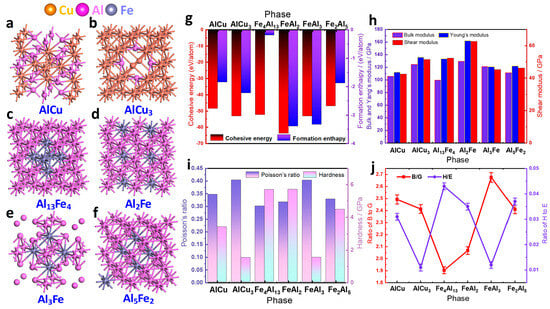
Figure 3.
Thermodynamic and mechanical properties of different intermetallic compounds: (a) AlCu atomic model; (b) AlCu3 atomic model; (c) Fe4Al14 atomic model; (d) FeAl2 atomic model; (e) FeAl3 atomic model; (f) Fe2Al5 atomic model; (g) cohesive energy and formation enthalpy; (h) variations in bulk modulus, shear modulus, and Young’s modulus; (i) variations in Poisson’s ratio and hardness; (j) B/G and H/E ratios.
As shown in Figure 3g, FeAl2 and FeAl3 have lower formation enthalpy and binding energy based on energy and atomic structure analysis. Therefore, they preferentially precipitate at the interface between the 2024 aluminum alloy and the 316L stainless steel and remain stable. Although FeAl3 also shows low energy, its atomic structure stability is relatively poor, and it is easy to partially transform into Fe2Al5 with more stable structure in the subsequent process. When the Cu content is sufficient, AlCu and AlCu3 can be formed and remain stable. In contrast, Fe4Al13 is difficult to form under conventional conditions due to its high formation energy. In summary, the main phases formed in the interfacial region are FeAl2, FeAl3, and Fe2Al5, with AlCu and AlCu3 appearing when the Cu content is adequate, while Fe4Al13 essentially does not form.
To further reveal and compare the strengthening mechanisms of different phases at the interface, the primary mechanical properties of AlCu, AlCu3, Fe4Al13, FeAl2, FeAl3, and Fe2Al5 were evaluated using first-principles calculations. The bulk modulus (B), shear modulus (G), Young’s modulus (E), and Poisson’s ratio (v) were calculated as follows [32,33,34]:
where BV, BR, GV, and GR can be obtained from the calculated elastic constants. The subscripts V and R denote the Voigt and Reuss methods, respectively. The label VRH indicates the results represented using the Voigt–Reuss–Hill approximation. Subsequently, the Vickers hardness (Hv) can be calculated using the empirical Equations (17) and (18) [35]:
According to the mechanical properties calculated in Figure 3, FeAl2 has the best comprehensive properties among Al2Fe, AlCu, AlCu3, Fe4Al13, FeAl3, and Fe2Al5 intermetallic compounds, with the highest bulk modulus, Young’s modulus, and shear modulus. This indicates that the formation of FeAl2 at the interface can simultaneously endow the material with high stiffness and good compressibility. When subjected to external loads, FeAl2 can resist irreversible deformation and shear stress, reducing the risk of interface spalling and cracking. Among the other compounds, AlCu3 ranks second only to FeAl2 in various moduli. Although its mechanical properties are not as prominent as FeAl2, it still has certain advantages. However, considering the stability of atomic structure, AlCu and AlCu3 are not ideal interface phases. Although the Poisson‘s ratio data shown in Figure 3i indicate that they have good deformation compatibility, Figure 3a,b confirm that their atomic structures are inherently unstable and prone to deformation under loading, which is detrimental to interface integrity.
According to the analysis of B/G and H/E ratios (Figure 3j), the interfacial behavior characteristics of different compounds were revealed. The lower B/G ratio indicates that the material tends to maintain shape rather than volume, showing the ability of elasticity to adapt to volume changes and inhibit shear slip. It is helpful to form an elastic buffer layer at the interface to provide shear stability. The higher H/E ratio reflects the combination of high stiffness and good toughness, which is beneficial to buffer stress and suppress cracks. FeAl2 and FeAl3 have the ideal combination: their low B/G and high H/E values can effectively alleviate the stress concentration caused by thermal expansion mismatch, lattice mismatch, or phase transformation, thus inhibiting the initiation and propagation of cracks and significantly enhancing the stability of interface bonding.
It is worth noting that Fe4Al13 exhibits excellent interface properties similar to FeAl2, but its formation requires harsh conditions in terms of cohesive energy and formation enthalpy. In contrast, FeAl2 not only has excellent comprehensive properties, but also has relatively good formation conditions. On the other hand, AlCu and AlCu3 exhibit completely opposite characteristics. The high B/G and low H/E ratios indicate that the corresponding compounds are prone to compressive deformation and shear slip under pressure. This behavior will directly cause stress concentration and crack formation at the interface, seriously weakening the interface bonding strength. In summary, based on systematic performance calculation and comparative analysis, the precipitation of FeAl2 should be preferentially promoted in the design of aluminum matrix composites to achieve the best interfacial bonding performance. If the process conditions permit, FeAl3 can be used as a useful supplement. The thermodynamic and mechanical properties data in Table 2 provide a complete theoretical basis for the interface design strategy.
Table 2.
Thermodynamic and mechanical properties of different intermetallic compounds.
3.2. Phase Analysis
Figure 4 shows the XRD patterns of aluminum matrix composites with different lattice structures. It can be observed that there are characteristic diffraction peaks of Al, FeAl3, and AlCu phases in all samples, and no other phases are detected. Under the process parameters of 850 °C for 2 h, FeAl3 phase was formed in all samples. However, the diffraction peak intensity increases significantly with the increase in the pillar diameter of the stainless steel lattice structure. The BCC-5-0.5 aluminum matrix composite is composed of matrix Al, FeAl3, and AlCu phases. First-principles calculations show that FeAl2 is more thermodynamically stable, but in the actual infiltration process, FeAl3 may be preferentially formed due to the influence of factors such as cooling rate and local composition fluctuation, which is consistent with the non-equilibrium solidification behavior reported in the literature [15]. The observation of the size of the lattice reinforcement shows that the stainless steel lattice structure has been dissolved, and its overall size remains basically unchanged.
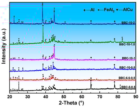
Figure 4.
The XRD curves of 316L lattice/Al composites with different aspect ratios.
When the lattice diameter is 0.5 mm and the length of the single edge of the lattice increases to 6.6 mm, the phases in the BCC-6.6-0.5 aluminum matrix composites are still matrix Al, FeAl3, and AlCu. The diffraction peak intensity of FeAl3 phase increases, which is mainly due to the increase in lattice dissolution, resulting in finer microstructure. Due to the BCC-6.6-0.5 lattice structure with more crystal cells, the infiltration path of the aluminum melt becomes longer. As the aluminum melt penetrates into the high-temperature stainless steel skeleton, it is continuously heated, even higher than the external temperature. At the same time, the small diameter (0.5 mm) has a large specific surface area, which is conducive to rapid mass transfer and dissolution of the lattice structure. The dissolved iron atoms then form FeAl3 during the cooling process, increasing its total amount, thereby enhancing the XRD peak intensity. In the BCC-10-0.5 sample, a large amount of iron dissolved into the aluminum melt, forming a large number of FeAl3 precipitates, resulting in the enhancement of XRD diffraction peaks. Compared with the BCC-5-0.5 lattice structure, the infiltration space of the BCC-10-0.5 lattice structure is larger, and the aluminum liquid is heated to an extremely high temperature inside it, resulting in local and rapid dissolution. Therefore, a large number of FeAl3 phases are formed in the aluminum matrix composites. When the lattice unit cell length is 10 mm and the lattice diameter increases to 1 mm, the specific surface area of the large-diameter lattice is much smaller than that of the small-diameter lattice, which increases the mass transfer rate of the aluminum-iron reaction. In addition, a sufficient iron source is provided. Therefore, the peak intensity of FeAl3 phase in the XRD pattern is enhanced. As the diameter of the compression bar further increases to 1.5 mm, the phase composition of the BCC-10-1.5 aluminum matrix composite remains unchanged, and only the diffraction peak intensity of the FeAl3 precipitated phase increases.
3.3. Macroscopic Morphology
Figure 5 shows the macroscopic morphology of BCC lattice-reinforced aluminum matrix composites with different aspect ratios. As shown in Figure 5a, there are unfilled pores in the BCC-5-0.5 sample. The main reason is that the wettability between the aluminum melt and the stainless steel is poor, which hinders the penetration under capillary drive. At the same time, the three-dimensional path of the lattice structure is highly tortuous, the melt flow resistance is large, and the momentum is easily dissipated before complete filling. In addition, needle-like precipitates can be seen in the matrix around the sample skeleton. The wettability between the melt and the skeleton and the lattice geometry are the key interface factors that determine the permeability integrity. The BCC-5-0.5 lattice structure has a high tortuosity flow channel, and the capillary resistance is dominant. Without surface modification of the skeleton, it is difficult for gravity to drive the melt to completely overcome the resistance, resulting in residual pores. Optimizing lattice geometry can effectively improve the infiltration behavior. When the diameter is fixed at 0.5 mm and the lattice unit cell length increases to 6.6 mm, as shown in Figure 1, the flow channel of sample BCC-6.6-0.5 is widened, the viscous resistance is reduced, and the melt is fully filled. In addition, a large number of needle-like precipitates growing inward are observed. When the lattice unit cell length increases to 10 mm (BCC-10-0.5), the flow channel is more open, the flow resistance is further reduced, and the number of hard phases growing along edge of the skeleton decreases. Therefore, better infiltration effect can be obtained by adjusting the lattice structure. When the lattice unit cell length is fixed to 10 mm and the lattice diameter is increased to 1 mm, 1.5 mm, and 2 mm, (BCC-10-1, BCC-10-1.5, BCC-10-2), the thicker pillar significantly improves the high-temperature stiffness of the frame, ensures the stable and rapid filling of the molten aluminum, shortens the penetration time, and avoids local blockage caused by structural softening or excessive interface reaction, thereby obtaining uniform and complete macroscopic forming (Figure 5d–f). In summary, infiltration integrity can be controlled by lattice geometry. The comparison between BCC-5-0.5 and BCC-10-1 shows that, under the premise of not changing the wettability of the interface, broadening the flow channel and enhancing the structural stability by optimizing the aspect ratio can compensate for the lack of wettability and achieve complete filling.
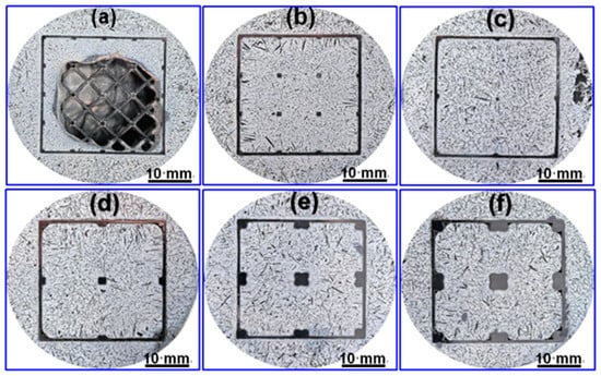
Figure 5.
Macroscopic morphology of 316L lattice/Al composites with different aspect ratios: (a) BCC-5-0.5; (b) BCC-6.6-0.5; (c) BCC-10-0.5; (d) BCC-10-1; (e) BCC-10-1.5; (f) BCC-10-2.
3.4. Microstructural Evolution
Figure 6 shows the metallographic structure of aluminum matrix composites with different samples. Figure 6a shows the typical microstructure of BCC-5-0.5 sample. Dark gray lath precipitates and bright white irregular block precipitates can be observed in the aluminum matrix. The dark gray precipitates are relatively coarse, and the slab width or equiaxed size is about 20–50 μm. In contrast, the size of bright white precipitates are about 5 μm, but they show irregular shapes and uneven distribution, showing obvious local aggregation characteristics. In addition, there are also a small amount of micro-porosity defects caused by poor melt fluidity or solidification shrinkage in the aluminum matrix. When the lattice unit cell length increases to 6.6 mm, the microstructure of the BCC-6.6-0.5 sample changes significantly. Compared with BCC-5-0.5, the dark gray lath phase becomes coarse, and the maximum lath width is about 80 μm. At the same time, the number of bright white phases increases, and the distribution is still uneven. Although the increase in lattice constant improves the macroscopic permeability, it also produces a new local stagnation zone. In these regions, the melt flow velocity decreases, while the local contact time between the aluminum melt and the stainless steel is prolonged. This provides favorable conditions for the diffusion of Fe and Cu elements and the coarsening of precipitated phases.
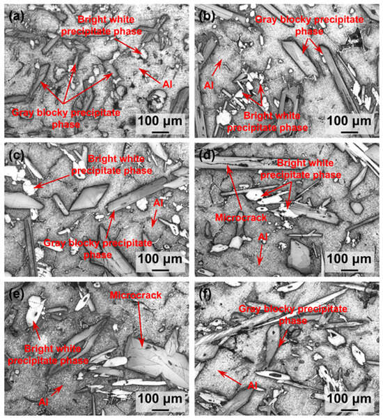
Figure 6.
Microstructure of 316L lattice/Al composites with different aspect ratios: (a) BCC-5-0.5; (b) BCC-6.6-0.5; (c) BCC-10-0.5; (d) BCC-10-1; (e) BCC-10-1.5; (f) BCC-10-2.
When the lattice unit cell length is further increased to 10 mm (sample BCC-10-0.5), the size and number of dark gray lath phase and bright white phase are increased compared with BCC-6.6-0.5, and the size of precipitated phase is about 100 μm. The main reason is the serious structural instability caused by the large aspect ratio of the lattice structure. The lattice diameter size collapses disorderly at high temperature. The wide flow channel, due to the mutual adhesion and stacking of the supports at the micro scale, produces many melt stagnation zones and reaction interfaces, and the reaction time is prolonged, which provides conditions for abnormal coarsening and the increase in the number of precipitated phases, resulting in the inhomogeneity of the microstructure.
Under the condition of fixed lattice unit cell length (10 mm), when the lattice diameter increases to 1–2 mm (Figure 6d–f), although the lattice diameter increases, the overall volume fraction of the interfacial reaction zone does not change significantly. This indicates that the reaction degree is mainly controlled by temperature (850 °C) and alloy composition and is less sensitive to local geometric parameters. The enhanced structural stiffness significantly changes the distribution and release process of residual stress. The lattice structure produces stronger constraints on the surrounding solidified aluminum matrix and brittle precipitates during cooling, resulting in higher thermal mismatch stress. Stress drives the long-range diffusion of solute elements, which reduces the distribution uniformity of the nearly hexagonal bright white phase and forms a hollow structure at its center due to insufficient feeding. In addition, local stress leads to dark gray strip fracture and induces the initiation of internal microcracks (Figure 6d,e).
Figure 7 shows the interface morphology of 316L lattice/aluminum composites. In all samples, the 316L lattice reinforcement maintains structural integrity and is completely wrapped by the aluminum matrix to achieve complete infiltration. It is worth noting that as the lattice unit cell length increases from 5 mm to 10 mm, the dissolution of the edge of the reinforcement is enhanced. It was observed between the 316L reinforcement and the aluminum matrix that the columnar crystal zone of about 10–15 μm on the matrix side was consistent with the solidification direction of the aluminum melt, forming a dense reaction layer, and its total thickness showed complex nonlinear changes with geometric parameters. The total interface layer of BCC-6.6-0.5 and BCC-10-1 samples is the thickest (about 33 μm and 37 μm, respectively), while the BCC-10-0.5 sample is relatively thin (about 23 μm). This change is due to the coupling effect of the aspect ratio on the thermal history of the melt and the high-temperature stability of the structure: a longer melt path (BCC-6.6-0.5) or a moderate specific surface area (BCC-10-1) promotes sufficient Fe-Al interdiffusion; however, the BCC-10-0.5 sample has a ‘severe structural collapse’ due to the excessively large aspect ratio, and its instability and distortion shorten the reaction time and inhibit the continuous uniform growth of the reaction layer. When the lattice diameter further increases (BCC-10-1.5, BCC-10-2), the structural stiffness enhancement inhibits the collapse, but the specific surface area decreases, resulting in a decrease in the thickness of the reaction layer. The dark gray lath phase and bright white block phase precipitates were observed in the aluminum matrix. When the lattice unit cell length is fixed at 10 mm and the lattice diameter increases to 1–2 mm, the thickness of the interfacial reaction layer tends to be stable, but the distribution of the precipitated phase changes, and the AlCu phase changes from a discrete distribution to a more continuous network distribution. In addition, microcracks appear in the sample, with lattice diameter ≥ 1.5 mm, which is directly related to the increase in thermal mismatch stress caused by the increase in the stiffness of the reinforcement.
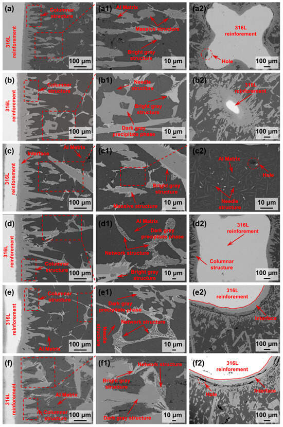
Figure 7.
BSE images of 316L lattice/Al composite interface region with different aspect ratios: (a–a2) BCC-5-0.5; (b–b2) BCC-6.6-0.5; (c–c2) BCC-10-0.5; (d–d2) BCC-10-1; (e–e2) BCC-10-1.5; (f–f2) BCC-10-2.
Figure 8 shows the backscattered electron (BSE) images of the internal structure of different lattice-reinforced aluminum matrix composites. The comparative analysis shows that with the increase in lattice unit cell length, the morphology, thickness, and growth characteristics of the internal interface reaction layer show systematic changes. As shown in Figure 8a, a light gray continuous layered structure of about 20 μm was formed at the interface of the BCC-5-0.5 sample. The layer is closely combined with the stainless steel skeleton, showing a continuous and uniform thin layer characteristics. The penetration of the reaction layer to the aluminum matrix is limited, and there are only a small number of small, irregular needle-like or short rod-like phases, indicating that the penetration depth is shallow. When the lattice unit cell length increases to 6.6 mm, it can be seen from Figure 8b that in sample BCC-6.6-0.5, the thickness of the reaction layer increases significantly, reaching about 30 μm. The transition region between the reaction layer and the 316L lattice can be observed, and the interface layer is continuous, with local coarsening and outward growth. Figure 8c shows that when the lattice unit cell length is further increased to 10 mm, sample BCC-10-0.5 is still metallurgically bonded at the interface, and no cracks appear. The long strip phase is clearly visible and grows from the interface to the aluminum matrix, indicating that the reaction phase has obvious directional growth behavior.
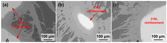
Figure 8.
BSE images of the internal framework/matrix interfacial regions in the aluminum matrix composite samples: (a) BCC-5-0.5; (b) BCC-6.6-0.5; (c) BCC-10-0.5.
3.5. EDS Analysis
According to the EDS element distribution map (Figure 8 and Figure 9) and the corresponding point analysis results, the diffusion behavior and interfacial reaction characteristics of different elements in the composite material are clearly revealed. Fe is mainly enriched in the stainless steel skeleton and the adjacent interface area, and its content in the matrix precipitates (such as point A, F, L, M, Q, U) formed after partial interface reaction is high, and there is a sign of diffusion into the aluminum matrix. Cu is mainly enriched in bright white precipitates (such as D, G, J, O, Q, U). Cr and Ni elements are mainly retained in the reinforcement, but Cr is observed to be distributed in the dark gray hard phase in multiple interface areas such as D, G, J, N, R, T, and X. Because the atomic radius and electronegativity of Cr and Fe are similar, Cr can easily replace Fe, so it is speculated that an (Fe, Cr)Al3 intermetallic compound is formed. This phenomenon is closely related to the enhancement of element diffusion ability under solid–liquid reaction conditions. Fe atoms diffuse into the matrix Al, forming a composition gradient in the interface region. For example, the aluminum content of the O point reaches 86.1 %, indicating deep penetration and participation in the interfacial reaction. With the increase in element interaction, a variety of intermetallic compounds, such as iron-rich phases (e.g., FeAl3), may be formed in the interface region, which is related to the non-equilibrium diffusion and reaction kinetics at high temperature. The composition of some regions (such as K, P, S, and V points) is close to that of pure aluminum, indicating that these regions are areas where no obvious reaction occurs in the aluminum matrix.
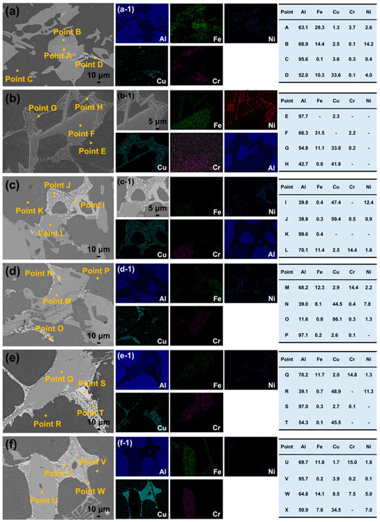
Figure 9.
BSE images and corresponding EDS elemental mapping of the aluminum matrix composites: (a,a-1) BCC-5-0.5; (b,b-1) BCC-6.6-0.5; (c,c-1) BCC-10-0.5; (d,d-1) BCC-10-1; (e,e-1) BCC-10-1.5; (f,f-1) BCC-10-2.
The EDS analysis results at the interface (Figure 10) show that the element diffusion behavior of the composites changes with the change in lattice geometric parameters. In the BCC-5-0.5 structure, Fe is mainly distributed in the 316L reinforcement and the interface region, while Cr and Ni are enriched in the reinforcement. Only a small amount of Cr is segregated in the matrix near the interface, and Al diffuses to the reinforcement and forms an obvious interface. When the length of the lattice unit cell increases to 10 mm and the diameter remains 0.5 mm, the element diffusion is significantly intensified, and a large amount of Fe enters the matrix and forms a needle-like phase. If the lattice diameter is further increased to 1 mm and 1.5 mm (the lattice unit cell length is maintained at 10 mm), the distribution characteristics of Cr in the matrix are more obvious, and Al has fully infiltrated into the reinforcement to form more rod-like structures. From the changes in the lattice structure, it can be seen that the increase in aspect ratio, caused by increasing the length of lattice unit cell or decreasing the lattice diameter changes the infiltration path and local thermal history of Al melt, significantly prolongs the high-temperature reaction time, and promotes the diffusion flux of Fe and other elements to Al melt. This significantly increases the driving force, thus providing sufficient thermodynamic and material conditions for the continuous growth of intermetallic compounds (such as FeAl3), eventually leading to the formation of coarse lath-like structures with equal size.
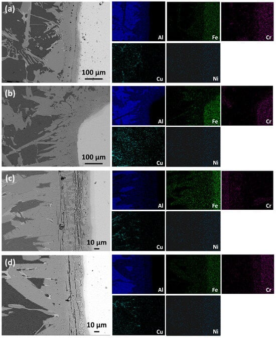
Figure 10.
The microstructure and corresponding element distribution of 316L lattice/Al composites prepared under different structural parameters: (a) BCC-5-0.5; (b) BCC-10-0.5; (c) BCC-10-1; (d) BCC-10-1.5.
3.6. Electron Probe Microanalysis
To precisely analyze the micro-phase composition and elemental spatial distribution characteristics within the framework region of the BCC-10-1 sample, EPMA characterization was performed. Figure 11 presents the elemental mapping results of the matrix region in the BCC-10-1 sample. The results indicate that the large, light-gray contrast phase within the sample’s framework region contains a high concentration of Fe, while the contents of Cu and Ni are relatively low. This is consistent with the previously identified phase being FeAl3. In sharp contrast, the network structure widely distributed in the gaps of the FeAl3 phase or attached to its surface shows almost no signal in the Fe elemental channel in the EPMA maps. However, it exhibits very high signal intensity in the Cu elemental channel, confirming that this network phase is the AlCu phase.
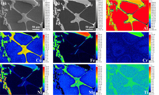
Figure 11.
EPMA elemental mapping of sample BCC-10-1: (a) Secondary electron image; (b) Composition comparison diagram; (c) Element mapping.
Consistent with the analysis presented earlier, both low-magnification and high-magnification EPMA images uniformly reveal the presence of micro-regions exhibiting a needle-like or irregular particulate morphology within or immediately adjacent to the Cu-rich network structure. These micro-regions show exceptionally high Ni signal intensity, appearing as bright white aggregates in the corresponding maps.
The high-magnification EPMA elemental mapping results in Figure 12 reveal that the analyzed fine needle-like precipitates are enriched in Cu and Mg elements. During the high-temperature processing and subsequent cooling of the 2024 aluminum alloy, solid-state phase transformations and age precipitation occur within the aluminum alloy matrix itself. EPMA analysis also identified micro-regions with more complex chemistries. Some areas exhibiting bright white contrast are simultaneously enriched in Fe, Cu, and Ni elements, potentially corresponding to incomplete reaction transition zones between the stainless steel framework and the aluminum matrix, or possibly the formation of multi-component composite phases. Other gray, fragmented areas show anomalous enrichment of Ni. These phenomena collectively reflect the high complexity of phase equilibrium and phase transformation processes within the sample.
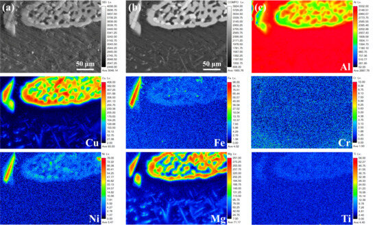
Figure 12.
High-magnification EPMA elemental mapping of the internal framework region in sample BCC-10-1: (a) Secondary electron image; (b) Composition comparison diagram; (c) Element mapping.
3.7. Hardness
The Vickers hardness test results of samples with different aspect ratios and pure aluminum reference samples are shown in Figure 13. As a matrix reference, the hardness value of the pure aluminum sample is stable between 138 and 142 Hv. In the skeleton area with a diameter of 0.5 mm, the Vickers hardness is distributed between 240 and 250 Hv, which is significantly higher than that of the aluminum matrix. When the pillar diameter increases to 2 mm, the hardness of the frame area further increases to about 265 Hv. This phenomenon can be attributed to the size effect: the skeleton with larger diameter has higher structural integrity, and the proportion of interfacial reactions during the preparation process is relatively low, thus better retaining the inherent high hardness of 316L stainless steel. In the interface bonding zone adjacent to the skeleton, the hardness value shows a significant peak, and the local maximum value is as high as 192 Hv. The increase in hardness in this region is attributed to the hard brittle reaction layer formed by the interface reaction, which is mainly composed of FeAl3 intermetallic compounds. In addition, the hardness gradient from the skeleton to the matrix shows obvious sample dependence. For the BCC-5-0.5 and BCC-6.6-0.5 samples, the hardness decreases in the transition zone. This is mainly because the hard interface reaction layer in these samples is relatively thin and discontinuous. Therefore, during the test process, the Vickers indentation can easily cross the narrow hard zone, which is significantly affected by the surrounding softer aluminum matrix, resulting in a rapid decrease in the measured hardness value. In contrast, samples with thicker and more continuous interface layers are expected to show a slower hardness transition from the skeleton to the matrix.
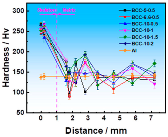
Figure 13.
Vickers hardness values of samples with different aspect ratios.
Figure 14 presents the microhardness test results for various phases in samples with different aspect ratios. Measurements of the different micro-constituent phases reveal significant differences in their hardness values, which are closely related to the phase type, morphology, and sample parameters. The test results indicate that the aluminum matrix consistently exhibits the lowest hardness in all samples, stabilizing at approximately 140 Hv, which aligns with the inherent properties of pure aluminum. In contrast, the stainless steel framework, serving as the reinforcement, demonstrates the highest hardness, generally exceeding 250 Hv, significantly strengthening the composite material. Notably, various hard phases distributed within the interfacial bonding region and the aluminum matrix display exceptionally high hardness values. Specifically, the interfacial hard phase and the lath-shaped hard phase in the BBC-6.6-0.5 sample reached peak hardness values of approximately 925 Hv and 929 Hv, respectively, far exceeding those of similar phases in other samples. This suggests that, under this specific geometric parameter, the interfacial reaction likely generated intermetallic compounds (such as Fe-Al and Al-Cr phases) with a higher volume fraction or greater strengthening effect.
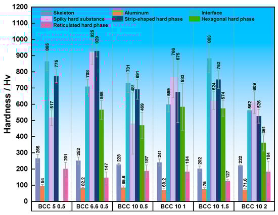
Figure 14.
Microhardness values of 316L lattice/Al composite specimens with different aspect ratios.
Furthermore, the hardness of the network-like AlCu phase shows a dependence on sample parameters. In the 5-0.5 sample, the hardness of this phase was about 201 Hv. However, when the lattice constant increased to 6.6 mm (6.6-0.5 sample), its hardness dropped sharply to 147 Hv, approaching the level of the aluminum matrix. As the diagonal length further increased to 10 mm, the hardness of the AlCu phase recovered and stabilized within the range of 180–190 Hv. Overall, the variation in hardness values for the different micro-constituent phases across samples with different geometric parameters does not follow a simple, uniform trend. This phenomenon may be attributed to the crystallographic orientation anisotropy of the hard phases in different samples or regions, as well as variations in local chemical composition or micro-defect density, all of which can significantly influence the microhardness test results.
3.8. Compression Experiments
Figure 15 shows the compression stress–strain curves for 316L reinforcement material and 316L lattice/aluminum composite. Aluminum exhibits a low yield strength, typically resulting in a flat compression stress–strain curve that demonstrates excellent plastic deformation capability and toughness [29]. As shown in Figure 15a, the stress–strain curve of the 316L lattice structure exhibits the typical three-stage characteristics of porous materials, with the curve being controlled by the aspect ratio. The plateau region of the BCC-10-0.5 curve features low stress and significant fluctuations, manifesting macroscopically as Euler buckling and progressive layer-by-layer collapse. Each sudden drop and rebound in load, along with the formation of localized plasticity and redistribution of load, directly corresponds to the “severe disordered collapse” observed at the microscopic level. In contrast, the curve plateau of BCC-5-0.5 is more stable. It is speculated that the smaller lattice diameter tends to undergo plastic yielding and bending deformation, resulting in a more uniform failure process. In this system, the mechanical behavior is entirely governed by the topological geometry of the framework, with the aluminum matrix (if present) playing only a limited role in filling and constraining.
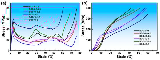
Figure 15.
(a) Compressive stress–strain curve of 316L lattice structure; (b) compressive stress–strain curve of 316L lattice/Al composites.
Figure 15b shows the compression stress–strain curve of the 316L lattice/aluminum composite. The composite exhibits enhanced compressive strength with a smooth and continuous curve. All specimens demonstrate compressive strengths exceeding 300 MPa, with the maximum compressive strength reaching approximately 400 MPa. The failure mechanism has shifted from unstable structural buckling to stable material plastic deformation and strengthening. The dense aluminum matrix provides robust lateral confinement to the lattice structure, effectively suppressing buckling instability. Additionally, the continuous interfacial reaction layer (FeAl3 compounds, etc.) formed via vacuum diffusion enables efficient shear load transfer from the ductile matrix to the high-strength skeleton. The skeleton, interface, and matrix undergo coordinated deformation to jointly bear the load. The BCC-10-0.5 composite exhibits a lattice structure prone to instability, yet maintains excellent compressive strength after composite formation. This indicates that, after the lattice structure collapses, the aluminum matrix becomes the primary load-bearing element. Meanwhile, the mechanical interlocking and residual bonding between the fragmented lattice structure fragments and the matrix still contribute partial load transfer capacity, demonstrating the damage tolerance of the composite material. Second is the role of brittle interfacial failure, such as the interfacial microcracks observed in some specimens. Excessively thick or brittle intermetallic compound layers may crack first at stress concentration points, serving as nucleation sites for macroscopic cracks.
3.9. Friction and Wear
To evaluate the effect of reinforcement frameworks with different aspect ratios on the friction and wear properties of the aluminum matrix composites, reciprocating friction and wear tests were conducted on each sample. Table 3 quantitatively summarizes the wear volume and wear rate of each sample, while Figure 16 visually presents the corresponding two-dimensional and three-dimensional morphologies of the wear scars. From the quantitative results, sample BCC-6.6-0.5 exhibited the poorest wear resistance, with both the highest wear volume (4.45 × 10⁻² mm3) and wear rate (7.41 × 10⁻⁴ mm3/(N·m)) among all samples. Analysis combined with its wear scar morphology (Figure 16b) reveals a relatively wide and uneven scar surface. This is closely related to its microstructure, where the aggregated distribution of hard phases and the presence of large softened areas in the matrix (as mentioned in the prior microstructural analysis) led to an uneven load-bearing capacity. In contrast, the wear resistance improved significantly for sample BCC-5-0.5, with a smaller lattice constant, and sample BCC-10-0.5, with a larger diagonal length. Their wear volumes were 2.31 × 10⁻² mm3 and 2.33 × 10⁻² mm3, respectively, and their wear rates were also very similar. Among all, sample BCC-10-1 demonstrated the most excellent wear performance, with the lowest wear volume (1.84 × 10⁻² mm3) and wear rate (3.07 × 10⁻⁴ mm3/(N·m)). Its corresponding 3D wear scar morphology (Figure 16d) also showed the shallowest and flattest scar, indicating a uniform load-bearing capacity and an effective wear resistance mechanism. This superior performance is attributed to its unique microstructure: the uniformly distributed the FeAl3 and AlCu phases in sample BCC-10-1 provided good hard support for the matrix.
Table 3.
Wear volume and wear rate of different 316L lattice/aluminum composite specimens.
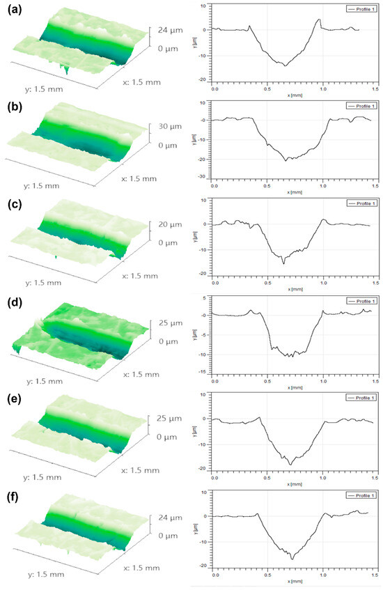
Figure 16.
Two-dimensional and 3D morphologies of the reciprocating friction and wear scars: (a) BCC-5-0.5; (b) BCC-6.6-0.5; (c) BCC-10-0.5; (d) BCC-10-1; (e) BCC-10-1.5; (f) BCC-10-2.
Simultaneously, the continuous and microcrack-free interfacial layer ensured effective load transfer, avoiding premature failure at the interface due to stress concentration. The synergistic effect of these two aspects effectively suppressed the occurrence of abrasive wear and delamination wear. However, the improvement in wear resistance did not change monotonically with increasing framework size. When the lattice constant was fixed at 10 mm and the strut diameter was further increased, as in samples BCC-10-1.5 and BCC-10-2, their wear volume and wear rate increased compared to BCC-10-1, indicating degraded wear resistance. Their wear scar morphologies also showed deeper plowing grooves and more pronounced signs of material delamination. In summary, the wear resistance of the composites strongly depends on the geometric parameters of the reinforcement framework. Under the conditions of this experiment, the geometric configuration of BCC-10-1 achieved the optimal balance among hard-phase distribution, matrix support, and interfacial bonding strength, resulting in the best wear performance. Excessively large or small framework spacing and diameter increased microstructural heterogeneity, thereby compromising the overall wear resistance of the material.
For the BCC-10-1 sample, the maximum wear scar depth under a 5 N load was only about 10 μm (Figure 16c). Among all six tested sample groups, this specimen exhibited the best wear resistance, with a wear rate as low as 3.07 × 10⁻⁴ mm3/(N·m). This result indicates that, within a certain range, increasing the diagonal length of the framework helps enhance the wear resistance of the composite material. However, when the lattice length was fixed at 10 mm and the diameter was increased to 1.5 mm (sample 10-1.5), its wear volume increased compared to the 10-1 sample, and the maximum wear scar depth under a 5 N load reached approximately 18 μm. When the diameter was further increased to 2 mm (sample 10-2), although its wear volume showed slight improvement compared to the 10-1.5 sample, the overall change was marginal. Therefore, under the experimental conditions of this study, merely increasing the strut diameter did not continuously and effectively improve the wear resistance of the composite material.
4. Conclusions
This study successfully fabricated 316L stainless steel lattice-reinforced aluminum matrix composites with different aspect ratios by combining laser powder bed fusion (LPBF) and vacuum infiltration technologies. The effects of the aspect ratio on the interfacial reaction, microstructure, compressive properties, and wear performance of the composites were systematically investigated, leading to the following main conclusions
- First-principles calculations show that FeAl2 and FeAl3 have lower formation enthalpy (−3.418 and −3.361 eV/atom, respectively) and higher cohesive energy, and their thermodynamic stability is better than that of the AlCu phase (−1.858 eV/atom). FeAl2 also exhibits the optimal elastic modulus (bulk modulus 129.5 GPa, shear modulus 62.6 GPa, Young’s modulus 162.3 GPa) and the moderate H/E ratio (0.035). In contrast, AlCu and AlCu3 have lower hardness (3.39 and 1.50 GPa, respectively) and a higher B/G ratio (both > 2.4).
- The phase of 316L lattice-structure-reinforced aluminum matrix composites is mainly composed of FeAl3, AlCu, and matrix Al. When the aspect ratio is too large, the lattice structure dissolves and collapses, which aggravates the diffusion of iron to the aluminum matrix and forms coarse FeAl3 precipitates. At the same time, continuous network AlCu is precipitated.
- Sample BCC-10-1 (L = 10 mm, D = 1 mm) has the best wear resistance, and its wear rate is as low as 3.07 × 10⁻⁴ mm3/(N·m). The Vickers hardness distribution further confirms the interface strengthening effect. The hardness of the stainless steel skeleton area exceeds 250 Hv, and a peak (>190 Hv) appears near the interface, forming a significant gradient with the aluminum matrix (140 Hv).
Author Contributions
Methodology, L.L. and J.W. (Jiacheng Wei); Software, L.L.; Formal analysis, L.L.; Resources, Y.L. (Yue Liu) and Y.L. (Yi Liu); Data curation, Y.L. (Yue Liu), L.W. and J.W. (Jiacheng Wei); Writing—original draft, L.L.; Writing—review & editing, L.L. and J.W. (Junfa Wang); Visualization, Y.L. (Yi Liu) and L.W.; Supervision, J.W. (Junfa Wang); Project administration, J.W. (Junfa Wang); Funding acquisition, J.W. (Junfa Wang). All authors have read and agreed to the published version of the manuscript.
Funding
The work was supported by the National Natural Science Foundation of China (U2570237)/52375326 and the China Aerospace Science Foundation Project (2022Z008077003).
Institutional Review Board Statement
Not applicable.
Informed Consent Statement
Not applicable.
Data Availability Statement
Data are contained within the article.
Conflicts of Interest
Author Longquan Wang was employed by the company Harbin Welding Research Institute Co., Ltd. The remaining authors declare that the research was conducted in the absence of any commercial or financial relationships that could be construed as a potential conflict of interest.
References
- Wang, Y.; Monetta, T. Systematic study of preparation technology, microstructure characteristics and mechanical behaviors for SiC particle-reinforced metal matrix composites. J. Mater. Res. Technol. 2023, 25, 7470–7497. [Google Scholar] [CrossRef]
- Shirvanimoghaddam, K.; Hamim, S.U.; Karbalaei, A.M.; Fakhrhoseini, S.M.; Khayyam, H.; Pakseresht, A.H.; Ghasali, E.; Zabet, M.; Munir, K.S.; Jia, S.; et al. Carbon fiber reinforced metal matrix composites: Fabrication processes and properties. Compos. Part A Appl. Sci. Manuf. 2017, 92, 70–96. [Google Scholar]
- McMullen, P. Fibre/resin composites for aircraft primary structures: A short history, 1936–1984. Composites 1984, 15, 222–230. [Google Scholar] [CrossRef]
- Lu, K. The future of metals. Science 2010, 328, 319–320. [Google Scholar] [CrossRef]
- Tian, X.; Zhao, Z.; Wang, H.; Liu, X.; Song, X. Progresses on the additive manufacturing of functionally graded metallic materials. J. Alloys Compd. 2023, 960, 170687. [Google Scholar] [CrossRef]
- Zhang, M.; Yu, Q.; Liu, Z.; Zhang, V.; Tan, G.; Jiao, D.; Zhu, W.; Li, S.; Zhang, Z.; Yang, R.; et al. 3D printed Mg-NiTi interpenetrating-phase composites with high strength, damping capacity, and energy absorption efficiency. Sci. Adv. 2020, 6, 5581–5589. [Google Scholar] [CrossRef]
- Bauer, J.; Sala-Casanovas, M.; Amiri, M.; Valdevit, L. Nanoarchitected metal/ceramic interpenetrating phase composites. Sci. Adv. 2022, 8, 3080. [Google Scholar] [CrossRef]
- Kota, N.; Charan, M.S.; Laha, T.; Roy, S. Review on development of metal/ceramic interpenetrating phase composites and critical analysis of their properties. Ceram. Int. 2022, 48, 1451–1483. [Google Scholar] [CrossRef]
- Wang, Y.; Zhou, Y.; Lin, L.; Corker, J.; Fan, M. Overview of 3D additive manufacturing (AM) and corresponding AM composites. Comp. Part A Appl. Sci. Manufac 2020, 139, 106114. [Google Scholar] [CrossRef]
- Xu, S.; Yang, X.; Hu, X.Z.; Liu, P.; Zhang, S.; Pan, Y.F.; Ren, G.C. Relation between materials, process, structure and property of metallic porous bone scaffolds fabricated by laser powder bed fusion (LPBF): A review. Opt. Laser Technol. 2025, 191, 113377. [Google Scholar] [CrossRef]
- Pelanconi, M.; Zavattoni, S.; Cornolti, L.; Puragliesi, R.; Arrivabeni, E.; Ferrari, L.; Gianella, S.; Barbato, M.; Ortona, A. Application of ceramic lattice structures to design compact, high temperature heat exchangers: Material and architecture selection. Materials 2021, 14, 3225. [Google Scholar] [CrossRef]
- Liang, D.; He, G.; Chen, W.; Chen, Y.; Chyu, M.K. Fluid flow and heat transfer performance for micro-lattice structures fabricated by selective laser melting. Int. J. Therm. Sci. 2022, 172, 107312. [Google Scholar] [CrossRef]
- Ghanadi, N.; Son, K.; Alvarado, M.; Yang, S.; Kao, H.M.; Chang, C.H.; Paul, B.K.; Pasebani, S. Effect of LPBF Processing Parameters on Inconel 718 Lattice Structures: Geometrical Characteristics, Surface Morphology, and Mechanical Properties. Mater. Des. 2025, 253, 113864. [Google Scholar] [CrossRef]
- Hamza, A.; Liang, H. Christopher Smith Fracture toughness and tensile strength of 316L stainless steel cellular lattice structures manufactured using the selective laser melting technique. Mater. Sci. Eng. A 2016, 669, 1–6. [Google Scholar]
- Wang, C.J.; Wang, C.; He, Y.H.; Zhang, Z.J.; Zhang, Y. Mechanical properties of novel 3D printing 316L stainless steel honeycomb structure reinforced aluminum matrix composites. Intermetallics 2025, 181, 108743. [Google Scholar] [CrossRef]
- Hamada, A.; Mansour, E.H.; Matias, A.; Walaa, A.E.; Mohamed, A.K.; Elshokrofy, H.; Mustakangas, A.; Järvenpää, A.; Khedr, M. Strengthening aluminum matrix composite with additively manufactured 316L stainless steel lattice reinforcement: Processing methodology, mechanical performance and deformation mechanism. J. Mater. Res. Technol. 2024, 29, 1087–1101. [Google Scholar] [CrossRef]
- Mandal, A.; Li, F.; Jia, X.; Pei, Y. Compressive deformation behavior of functionally graded lattice structures of stainless steel 316L. J. Mater. Res. Technol. 2025, 35, 4599–46613. [Google Scholar]
- Mirzababaei, S.; Doddapaneni, V.V.K.; Lee, K.; Paul, G.E.; Pirgazi, H.; Tan, K.S.; Ertorer, O.; Hung, C.; Paul, B.K.; Pasebani, S. Remarkable enhancement in thermal conductivity of stainless-steel leveraging metal composite via laser powder bed fusion: 316L-Cu composite. Addit. Manuf. 2023, 70, 103576. [Google Scholar]
- Statnik, E.S.; Somov, P.A.; Zherebtsov, D.D.; Saprykin, D.L.; Saprykin, L.G.; Chernovolov, V.V.; Polozov, N.A.; Salimon, A.I. Micro-scale residual stress and deformation analysis in bimetal bronze-stainless steel samples produced by laser powder bed fusion technology. Mater. Sci. Eng. 2022, 858, 144110. [Google Scholar]
- Pawlowski, A.E.; Cordero, Z.C.; French, M.R.; Muth, T.R.; Keith Carver, J.; Dinwiddie, R.B.; Elliott, A.M.; Shyam, A.; Splitter, D.A. Damage-tolerant metallic composites via melt infiltration of additively manufactured preforms. Mater. Des. 2017, 127, 346–351. [Google Scholar] [CrossRef]
- Malaki, M.; Tehrani, A.F.; Niroumand, B.; Gupta, M. Wettability in metal matrix composites. Metals 2021, 11, 1034. [Google Scholar] [CrossRef]
- Poole, L.L.; Gonzales, M.; French, M.R.; Yarberry, W.A.; Moustafa, A.R.; Cordero, Z.C. Hypervelocity impact of PrintCast 316L/A356 composites. Int. J. Impact Eng. 2020, 136, 103407. [Google Scholar]
- Moustafa, A.R.; Dinwiddie, R.B.; Pawlowski, A.E.; Splitter, D.A.; Shyam, A.; Cordero, Z.C. Mesostructure and porosity effects on the thermal conductivity of additively manufactured interpenetrating phase composites. Addit. Manuf. 2018, 22, 223–229. [Google Scholar] [CrossRef]
- Ghasri-Khouzani, M.; Li, X.; Bogno, A.A.; Chen, Z.; Liu, J.; Henein, H.; Qureshi, A.J. Fabrication of aluminum/stainless steel bimetallic composites through a combination of additive manufacturing and vacuum-assisted melt infiltration casting. J. Manuf. Process 2021, 69, 320–330. [Google Scholar]
- Shih, T.S.; Tu, S.H. Interaction of steel with pure Al, Al-7Si and A356 alloys. Mater. Sci. Eng. 2007, 454, 349–356. [Google Scholar] [CrossRef]
- Wang, Y.; Liu, X.; Wang, H.; Vecchio, K. The effect of oxides on Fe/Al interfacial reaction in Metal-Intermetallic Laminate (MIL) composites. J. Alloy Compd. 2020, 845, 56268. [Google Scholar] [CrossRef]
- Wang, C.; Wang, C.J.; Li, Z.H.; Yao, B.; Zhang, Z.J.; Wang, B. Microstructure and properties of 316L lattice/Al composites by additive manufacturing and infiltration with different temperature. J. Mater. Process Technol. 2024, 329, 118441. [Google Scholar]
- Jian, Y.X.; Huang, Z.F.; Liu, X.T.; Xing, J.D. Comparative investigation on the stability, electronic structures and mechanical properties of Mo2FeB2 and Mo2NiB2 ternary borides by first-principles calculations. Results Phys. 2019, 15, 102698. [Google Scholar] [CrossRef]
- Wei, J.C.; He, Y.; Wang, F.; He, Y.Y.; Rong, X.X.; Chen, M.J.; Wang, Y.; Yue, H.H.; Liu, J.Y. Convolutional neural network assisted infrared imaging technology: An enhanced online processing state monitoring method for laser powder bed fusion. Infrared Phys. Technol. 2023, 131, 104661. [Google Scholar] [CrossRef]
- Wu, J.; Chong, X.Y.; Jiang, Y.H.; Feng, J. Stability, electronic structure, mechanical and thermodynamic properties of Fe-Si binary compounds. J. Alloys Compd. 2017, 693, 859–870. [Google Scholar] [CrossRef]
- Jian, Y.X.; Huang, Z.F.; Xing, J.D.; Sun, L.; Liu, Y.Z.; Gao, P.Y. Phase stability, mechanical properties and electronic structures of Ti-Al binary compounds by first principles calculations. Mater. Chem. Phys. 2019, 221, 311–321. [Google Scholar] [CrossRef]
- Kanga, M.; Kima, D.; Hwang, N. Ostwald ripening kinetics of angular grains dispersed in a liquid phase by two-dimensional nucleation and abnormal grain growth. J. Eur. Ceram. Soc. 2002, 22, 603–612. [Google Scholar] [CrossRef]
- Warren, R. Microstructral development during the liquid-sintering of VC-Co alloys. J. Mater. Sci. 1972, 7, 1434–1442. [Google Scholar] [CrossRef]
- Xiao, B.; Feng, J.; Zhou, C.T.; Jiang, Y.H.; Zhou, R. Mechanical properties and chemical bonding characteristics of Cr7C3 type multicomponent carbides. J. Appl. Phys. 2011, 109, 23507. [Google Scholar] [CrossRef]
- Chen, X.Q.; Niu, H.Y.; Li, D.Z.; Li, Y. Modeling hardness of polycrystalline materials and bulk metallic glasses. Intermetallics 2011, 19, 1275–1281. [Google Scholar] [CrossRef]
Disclaimer/Publisher’s Note: The statements, opinions and data contained in all publications are solely those of the individual author(s) and contributor(s) and not of MDPI and/or the editor(s). MDPI and/or the editor(s) disclaim responsibility for any injury to people or property resulting from any ideas, methods, instructions or products referred to in the content. |
© 2026 by the authors. Licensee MDPI, Basel, Switzerland. This article is an open access article distributed under the terms and conditions of the Creative Commons Attribution (CC BY) license.