

Experimental Study and Mechanism Analysis of the Influence of Micro-Dimple Geometry on the Adhesion Strength of Textured Coatings


Abstract
1. Introduction
2. Experimental Details
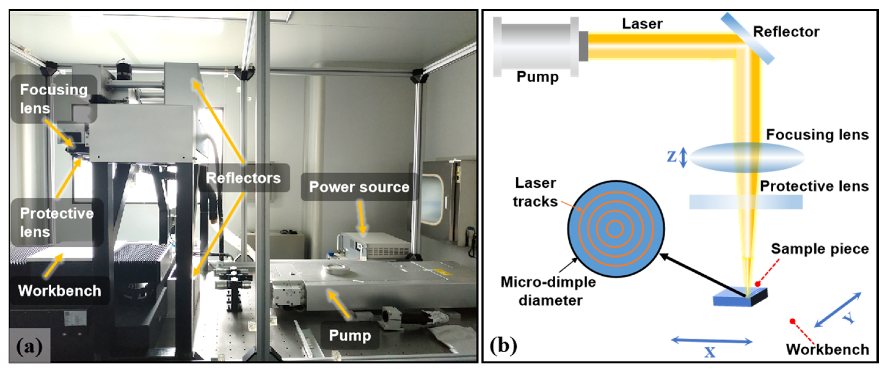
2.1. Sample Preparation
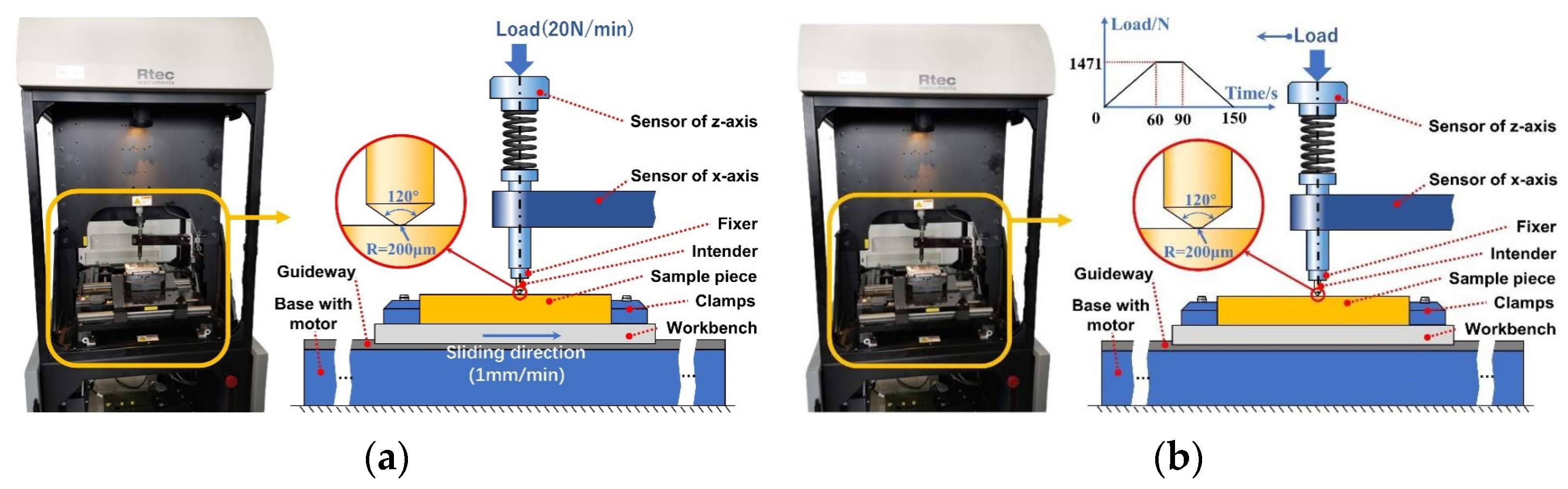
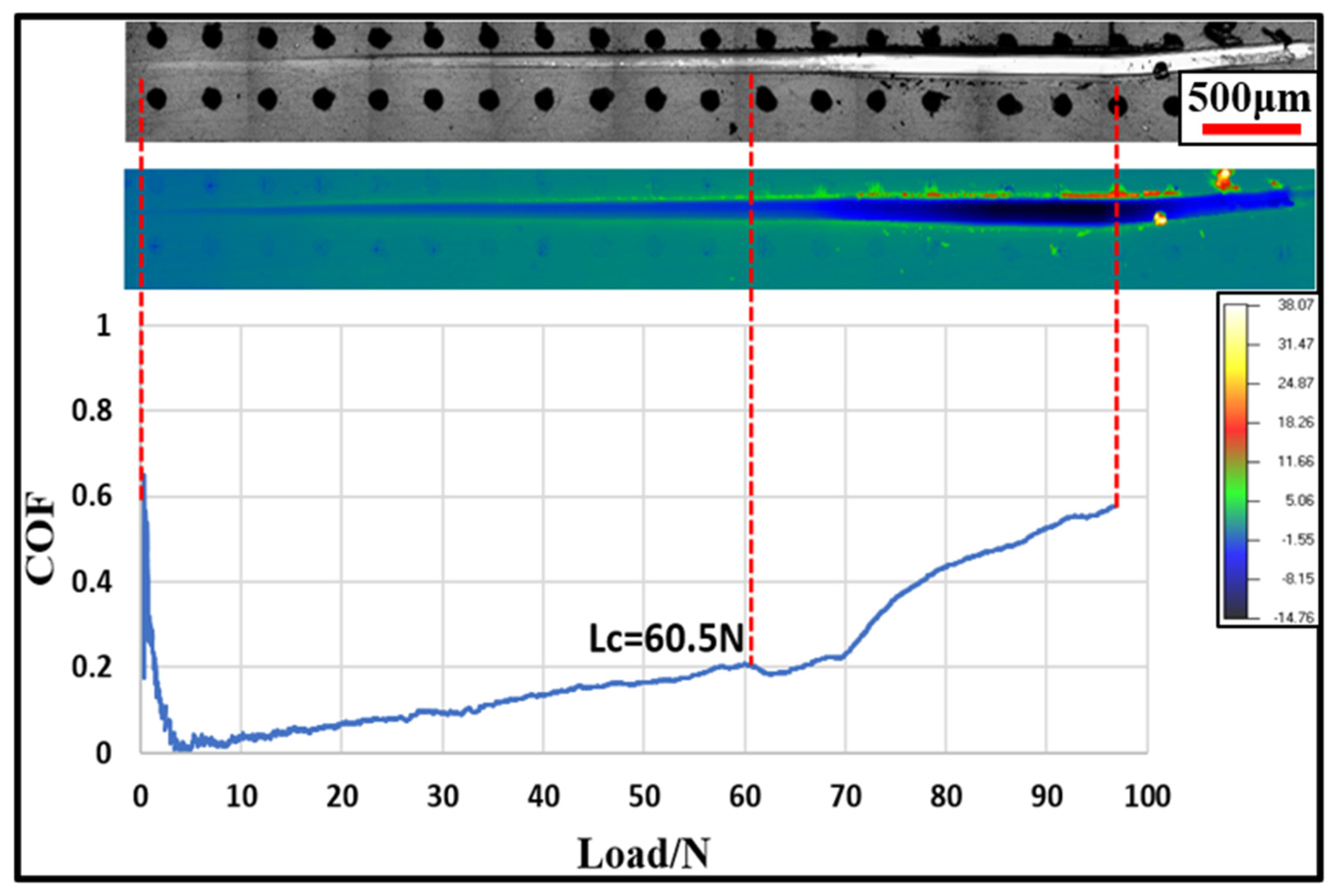
2.2. Scratch Test
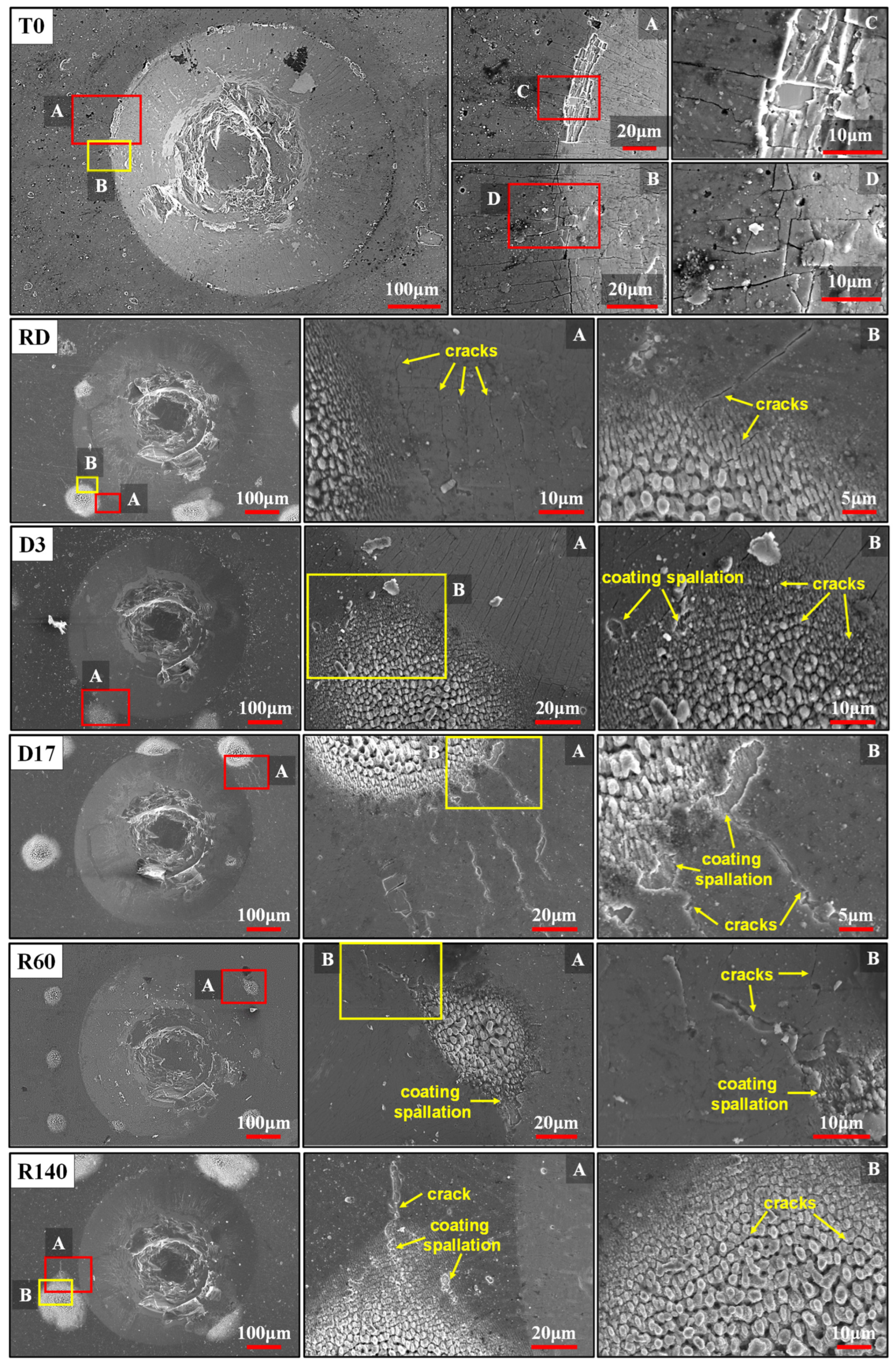
2.3. Indentation Test
3. Results and Discussion
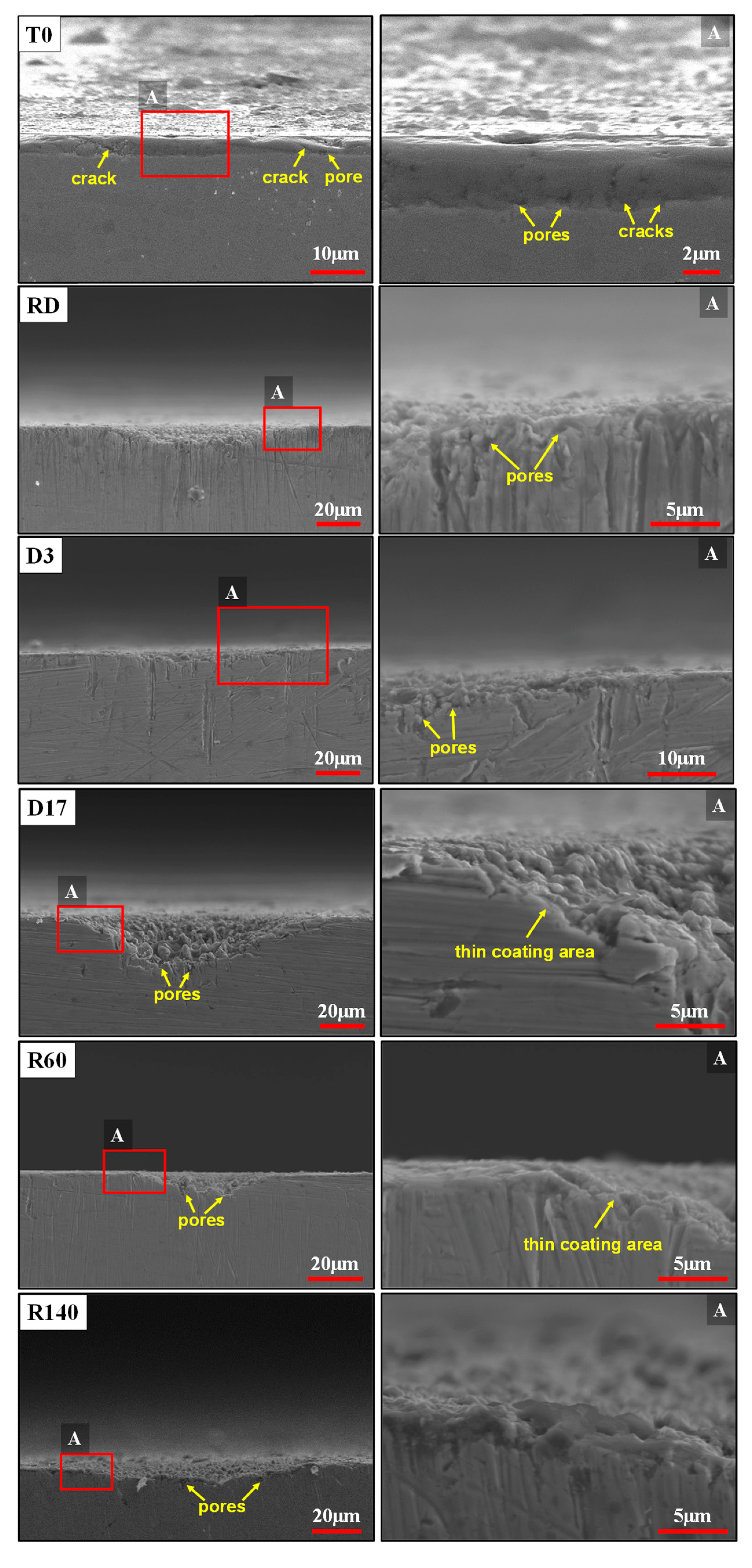
3.1. Coating Cross-Sectional Morphology
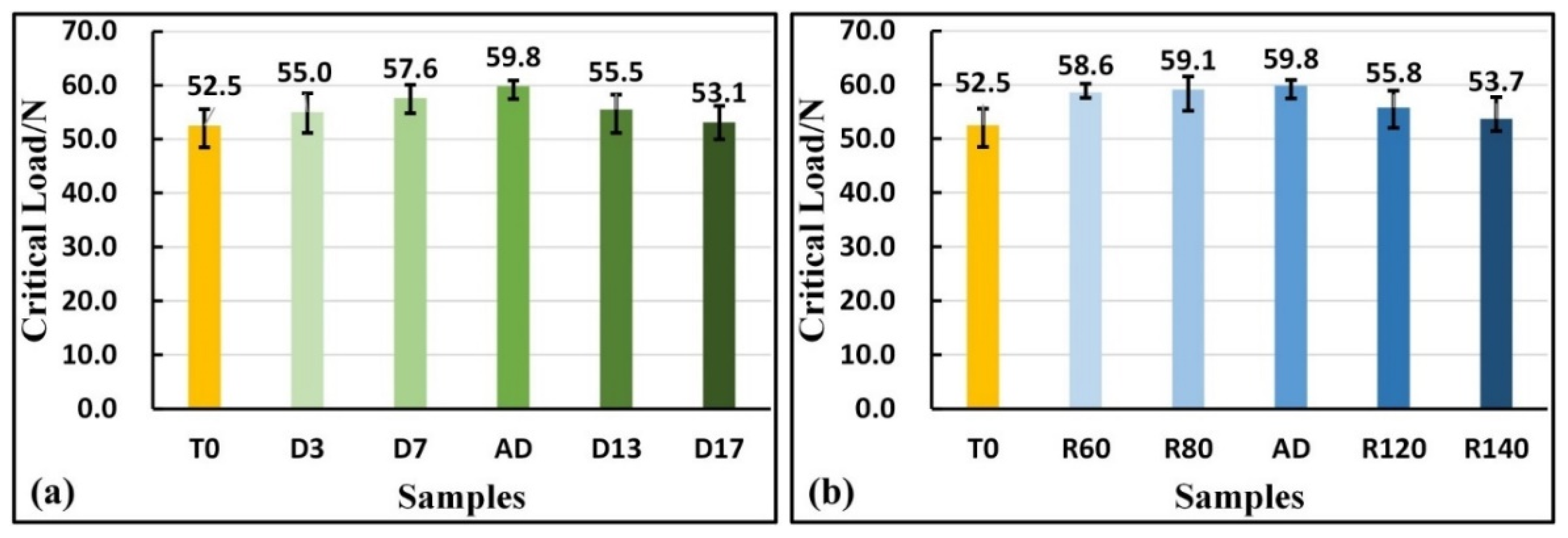
3.2. Adhesion Strength of Coatings under Dynamic Contact Conditions
3.3. Coating Crack Propagation Behavior under Static Contact Conditions
4. Conclusions
Author Contributions
Funding
Institutional Review Board Statement
Informed Consent Statement
Data Availability Statement
Conflicts of Interest
References
- Aliofkhazraei, M. Modern Surface Engineering Treatments; BoD–Books on Demand: Norderstedt, Germany, 2013. [Google Scholar]
- Bobzin, K.; Brögelmann, T.; Brugnara, R.H.; Kruppe, N.C. CrN/AlN and CrN/AlN/Al2O3 coatings deposited by pulsed cathodic arc for aluminum die casting applications. Surf. Coat. Technol. 2015, 284, 222–229. [Google Scholar] [CrossRef]
- Deng, Y.; Chen, W.; Li, B.; Wang, C.; Kuang, T.; Li, Y. Physical vapor deposition technology for coated cutting tools: A review. Ceram. Int. 2020, 46, 18373–18390. [Google Scholar] [CrossRef]
- Kumar CH, R.V.; Nair, P.K.; Ramamoorthy, B. Characterization of multilayer PVD nanocoatings deposited on tungsten carbide cutting tools. Int. J. Adv. Manuf. Technol. 2008, 38, 622–629. [Google Scholar] [CrossRef]
- Durairaj, S.; Guo, J.; Aramcharoen, A.; Castagne, S. An experimental study into the effect of micro-textures on the performance of cutting tool. Int. J. Adv. Manuf. Technol. 2018, 98, 1011–1030. [Google Scholar] [CrossRef]
- Boing, D.; De Oliveira, A.J.; Schroeter, R.B. Evaluation of wear mechanisms of PVD and CVD coatings deposited on cemented carbide substrates applied to hard turning. Int. J. Adv. Manuf. Technol. 2020, 106, 5441–5451. [Google Scholar] [CrossRef]
- He, Q.; Paiva, J.M.; Kohlscheen, J.; Beake, B.D.; Veldhuis, S.C. An integrative approach to coating/carbide substrate design of CVD and PVD coated cutting tools during the machining of austenitic stainless steel. Ceram. Int. 2020, 46, 5149–5158. [Google Scholar] [CrossRef]
- Lei, S.; Ji, X.; Tianen, Y. Friction and cutting performance of CVD/PVD coatings on the surfaces of metal ceramics and hard alloys. China Surf. Eng. 2019, 32, 45–55. [Google Scholar]
- Koyilada, B.; Gangopadhyay, S.; Thakur, A. Comparative evaluation of machinability characteristics of Nimonic C-263 using CVD and PVD coated tools. Measurement 2016, 85, 152–163. [Google Scholar] [CrossRef]
- Sam, Z. Thin Films and Coatings Toughening and Toughness Characterization; CRC Press: Boca Raton, FL, USA, 2016. [Google Scholar]
- Amada, S.; Hirose, T. Planar fractal characteristics of blasted surfaces and its relation with adhesion strength of coatings. Surf. Coat. Technol. 2000, 130, 158–163. [Google Scholar] [CrossRef]
- Xu, F.; Xu, J.H.; Yuen, M.F.; Zheng, L.; Lu, W.Z.; Zuo, D.W. Adhesion improvement of diamond coatings on cemented carbide with high cobalt content using PVD interlayer. Diam. Relat. Mater. 2013, 34, 70–75. [Google Scholar] [CrossRef]
- Li, T.; Lou, Q.; Dong, J.; Wei, Y.; Zhou, J.; Liu, J.; Zhang, Z.; Sun, F. Improved adhesion of diamond coating on cobalt-cemented tungsten carbide hardmetal by using pulsed-UV-laser substrate surface pretreatment. Appl. Surf. Sci. 2002, 193, 102–119. [Google Scholar]
- Xu, Y.; Peng, Y.; Dearn, K.D.; You, T.; Geng, J.; Hu, X. Fabrication and tribological characterization of laser textured boron cast iron surfaces. Surf. Coat. Technol. 2017, 313, 391–401. [Google Scholar] [CrossRef]
- Li, J.; Xiong, D.; Zhang, Y.; Zhu, H.; Qin, Y.; Kong, J. Friction and wear properties of MoS2-overcoated laser surface-textured silver-containing nickel-based alloy at elevated temperatures. Tribol. Lett. 2011, 43, 221–228. [Google Scholar] [CrossRef]
- Vlădescu, S.C.; Olver, A.V.; Pegg, I.G.; Reddyhoff, T. Combined friction and wear reduction in a reciprocating contact through laser surface texturing. Wear 2016, 358, 51–61. [Google Scholar] [CrossRef]
- Kromer, R.; Costil, S.; Cormier, J.; Courapied, D.; Berthe, L.; Peyre, P.; Boustie, M. Laser surface patterning to enhance adhesion of plasma sprayed coatings. Surf. Coat. Technol. 2015, 278, 171–182. [Google Scholar] [CrossRef]
- Neves, D.; Diniz, A.E.; Lima, M.S.F. Microstructural analyses and wear behavior of the cemented carbide tools after laser surface treatment and PVD coating. Appl. Surf. Sci. 2013, 282, 680–688. [Google Scholar] [CrossRef]
- Zhang, Z.; Lu, W.; Feng, W.; Du, X.; Zuo, D. Effect of substrate surface texture on adhesion performance of diamond coating. Int. J. Refract. Met. Hard Mater. 2021, 95, 105402. [Google Scholar] [CrossRef]
- Xu, C.; Xu, F.; Shi, L.; Gao, J.; Tu, L.; Zuo, D. Enhancement of substrate-coating adherence of boron-doped diamond electrodes by nanosecond laser surface texturing pretreatment. Surf. Coat. Technol. 2019, 360, 196–204. [Google Scholar] [CrossRef]
- Zhang, K.; Deng, J.; Meng, R.; Lei, S.; Yu, X. Influence of laser substrate pretreatment on anti-adhesive wear properties of WC/Co-based TiAlN coatings against AISI 316 stainless steel. Int. J. Refract. Met. Hard Mater. 2016, 57, 101–114. [Google Scholar] [CrossRef]
- Jhavar, S.; Paul, C.P.; Jain, N.K. Causes of failure and repairing options for dies and molds: A review. Eng. Fail. Anal. 2013, 34, 519–535. [Google Scholar] [CrossRef]
- Diao, D.F.; Kato, K.; Hokkirigawa, K. Fracture mechanisms of ceramic coatings in indentation. J. Tribol. Oct. 1994, 116, 860–869. [Google Scholar] [CrossRef]


| C | Si | Mn | Cr | Mo | V | Fe |
|---|---|---|---|---|---|---|
| 1.00 | 0.91 | 0.32 | 8.00 | 2.00 | 0.28 | balance |
| Parameters | Values |
|---|---|
| Wavelength (nm) | 1064 |
| Repetition rate (kHz) | 500 |
| Pulse width (ps) | 15 |
| Beam diameter (μm) | 60 |
| Morphological Parameters | Processing Parameters | |||||
|---|---|---|---|---|---|---|
| Sample Number | Depth (μm) | Diameter (μm) | Depth-to-Diameter Ratio | Power (W) | Current (A) | Number of Repetitions |
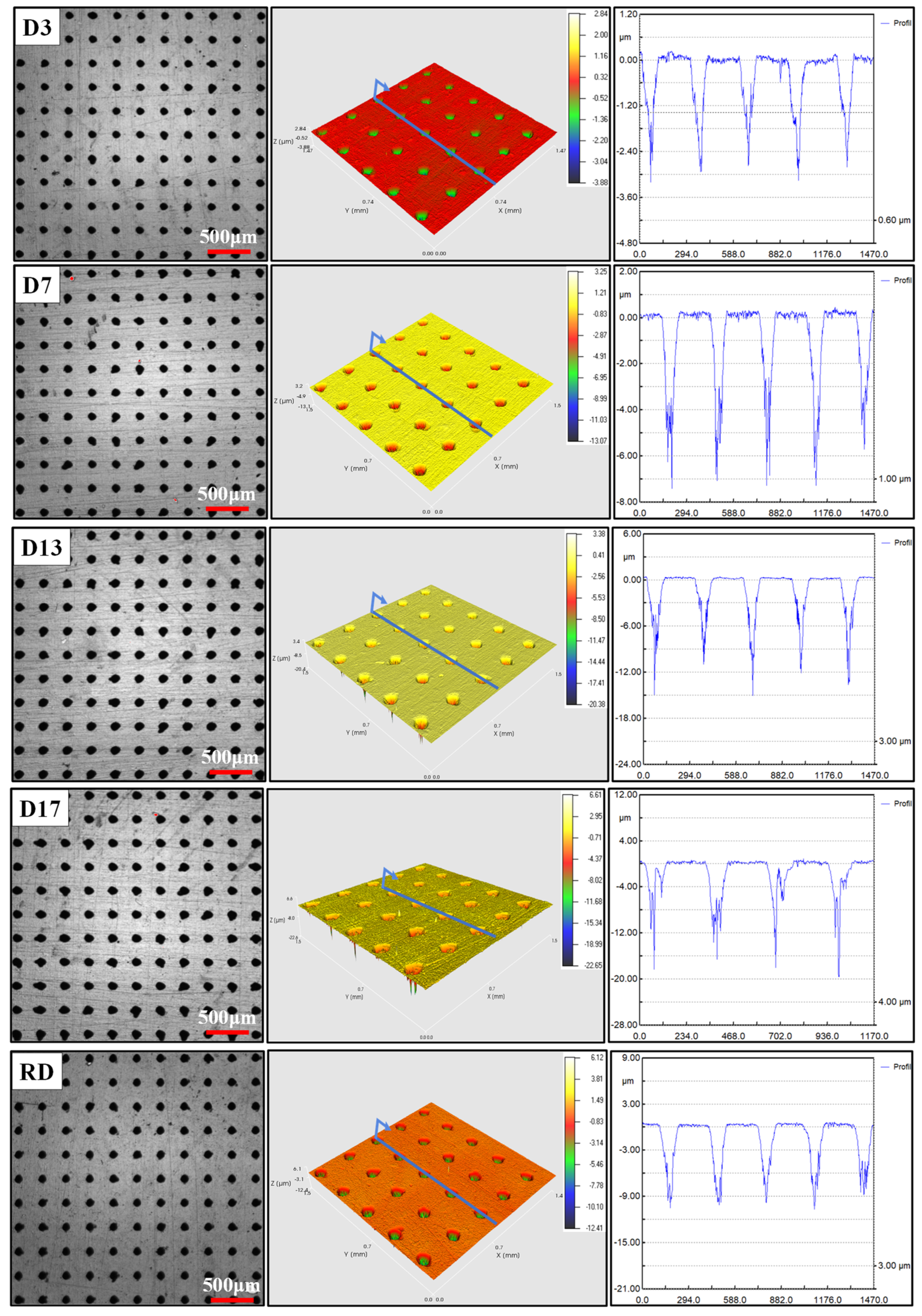
| D3 | 3 | 100 | 0.03 | 20.5 | 5.4 | 2 |
| D7 | 7 | 100 | 0.07 | 20.5 | 5.4 | 5 |
| D13 | 13 | 100 | 0.13 | 20.5 | 5.4 | 9 |
| D17 | 17 | 100 | 0.17 | 20.5 | 5.4 | 12 |
| RD | 10 | 100 | 0.10 | 20.5 | 5.4 | 7 |
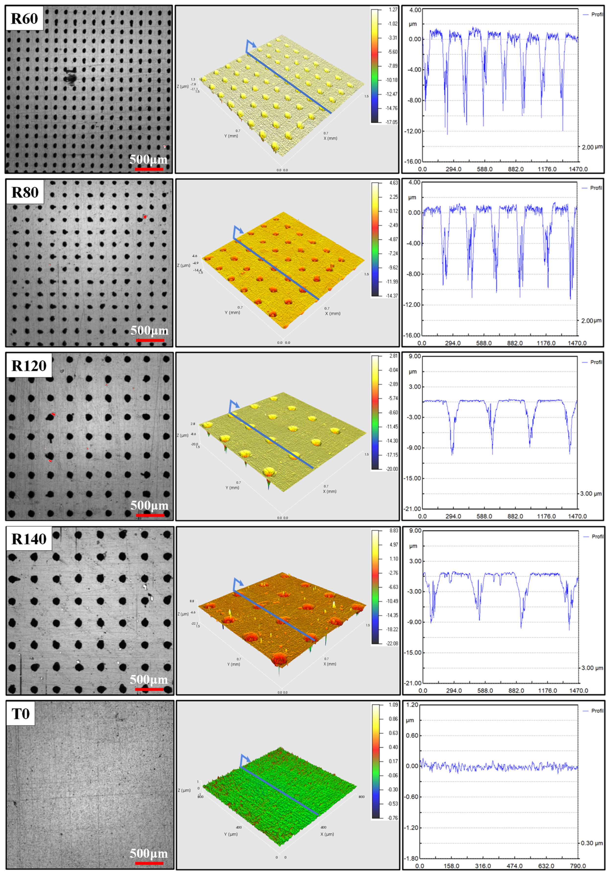
| R60 | 10 | 60 | 0.17 | 20.5 | 5.4 | 11 |
| R80 | 10 | 80 | 0.13 | 20.5 | 5.4 | 7 |
| R120 | 10 | 120 | 0.08 | 20.5 | 5.4 | 5 |
| R140 | 10 | 140 | 0.07 | 20.5 | 5.4 | 6 |
| T0 | No micro-dimple’s topography | No micro-dimple’s topography | ||||
| Al | Cr | N |
|---|---|---|
| 33.36 | 43.36 | 23.28 |
| Hardness (GPa) | Young’s Modulus (GPa) | Poisson’s Ratio | Coefficient of Thermal Expansion (10−6/°C) |
|---|---|---|---|
| 29 ± 3 | 358 | 0.25 | 7.5 |
| Deposition Temperature (°C) | Bias Voltage (V) | Deposition Time (min) | Gas Pressure (Pa) | Type of Gas |
|---|---|---|---|---|
| 420 | −100~−150 | 160 | 0.2 | Ar |
Disclaimer/Publisher’s Note: The statements, opinions and data contained in all publications are solely those of the individual author(s) and contributor(s) and not of MDPI and/or the editor(s). MDPI and/or the editor(s) disclaim responsibility for any injury to people or property resulting from any ideas, methods, instructions or products referred to in the content. |
© 2024 by the authors. Licensee MDPI, Basel, Switzerland. This article is an open access article distributed under the terms and conditions of the Creative Commons Attribution (CC BY) license (https://creativecommons.org/licenses/by/4.0/).
Share and Cite
Fu, H.; Yang, X.; Mei, M.; Yang, J.; Zhang, Y.; Ji, J.; Fu, Y. Experimental Study and Mechanism Analysis of the Influence of Micro-Dimple Geometry on the Adhesion Strength of Textured Coatings. Coatings 2024, 14, 973. https://doi.org/10.3390/coatings14080973
Fu H, Yang X, Mei M, Yang J, Zhang Y, Ji J, Fu Y. Experimental Study and Mechanism Analysis of the Influence of Micro-Dimple Geometry on the Adhesion Strength of Textured Coatings. Coatings. 2024; 14(8):973. https://doi.org/10.3390/coatings14080973
Chicago/Turabian StyleFu, Hao, Xiao Yang, Mei Mei, Jie Yang, Yanhu Zhang, Jinghu Ji, and Yonghong Fu. 2024. "Experimental Study and Mechanism Analysis of the Influence of Micro-Dimple Geometry on the Adhesion Strength of Textured Coatings" Coatings 14, no. 8: 973. https://doi.org/10.3390/coatings14080973
APA StyleFu, H., Yang, X., Mei, M., Yang, J., Zhang, Y., Ji, J., & Fu, Y. (2024). Experimental Study and Mechanism Analysis of the Influence of Micro-Dimple Geometry on the Adhesion Strength of Textured Coatings. Coatings, 14(8), 973. https://doi.org/10.3390/coatings14080973