

NIR to LWIR Dichroic Beamsplitter Designed and Manufactured for Space Optical Remote Sensor


Abstract
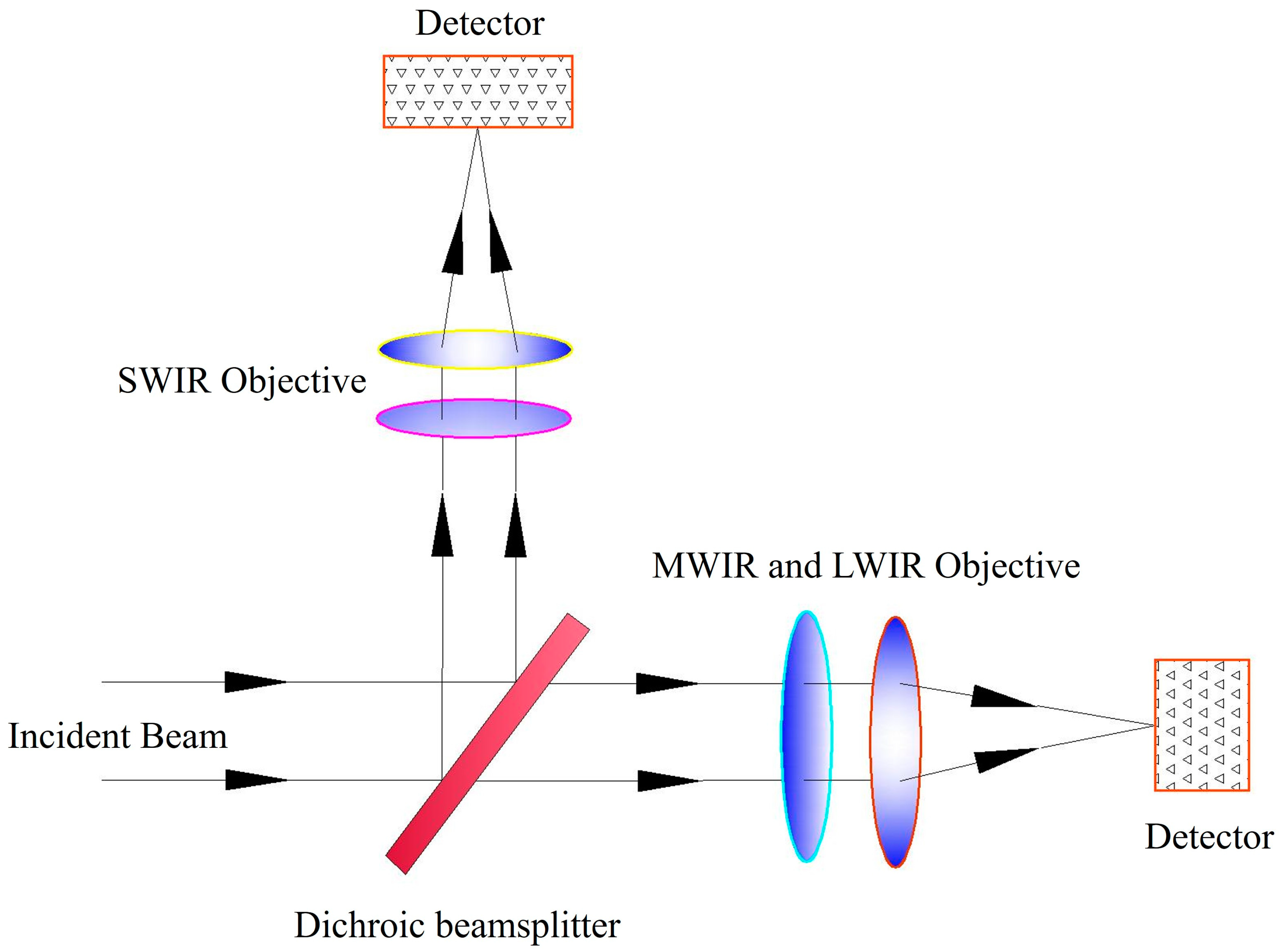
1. Introduction
2. Materials and Methods
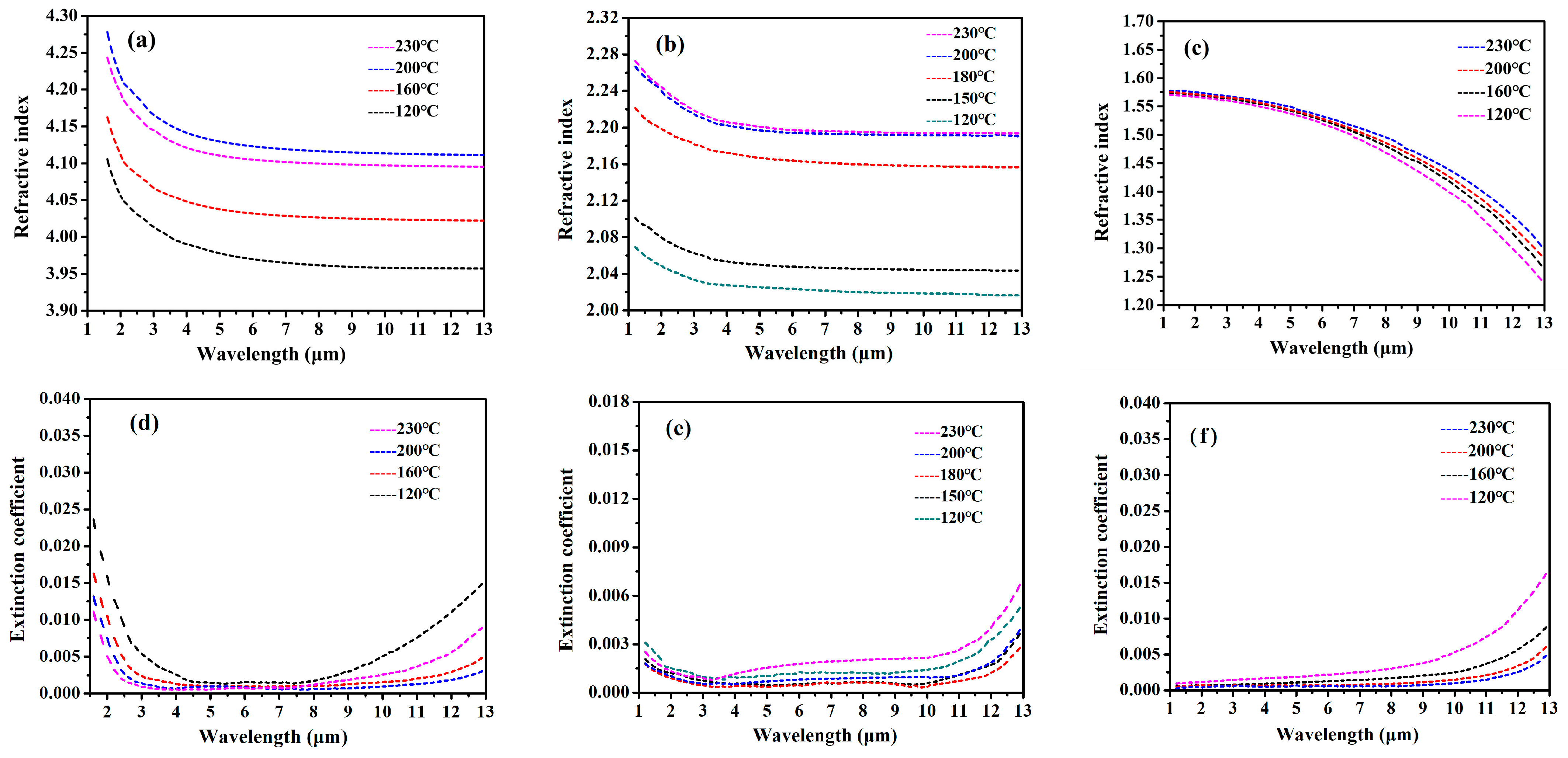
2.1. Selection of Materials
2.2. Optical Coating Design
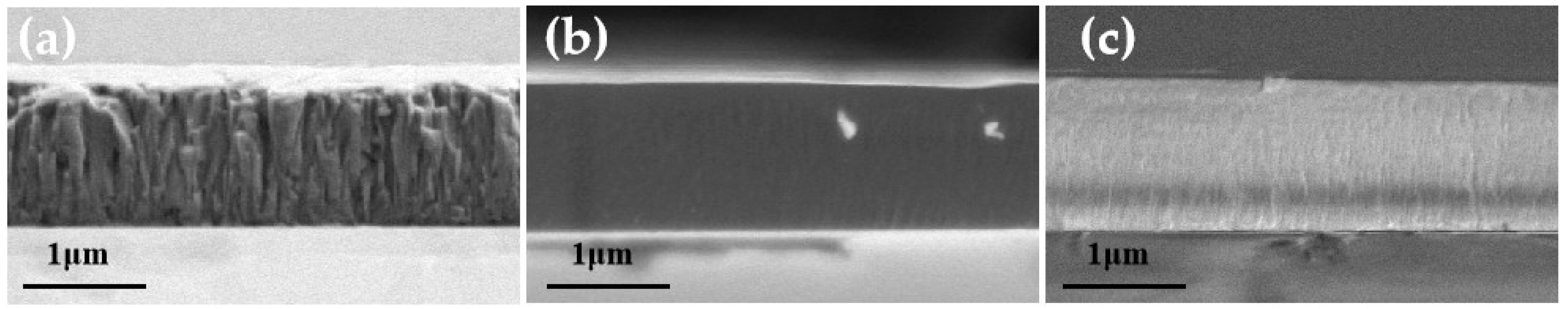
2.3. Experimentation and Characterization
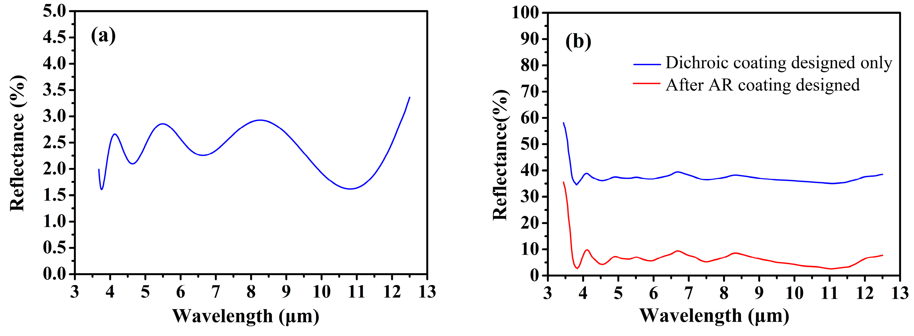
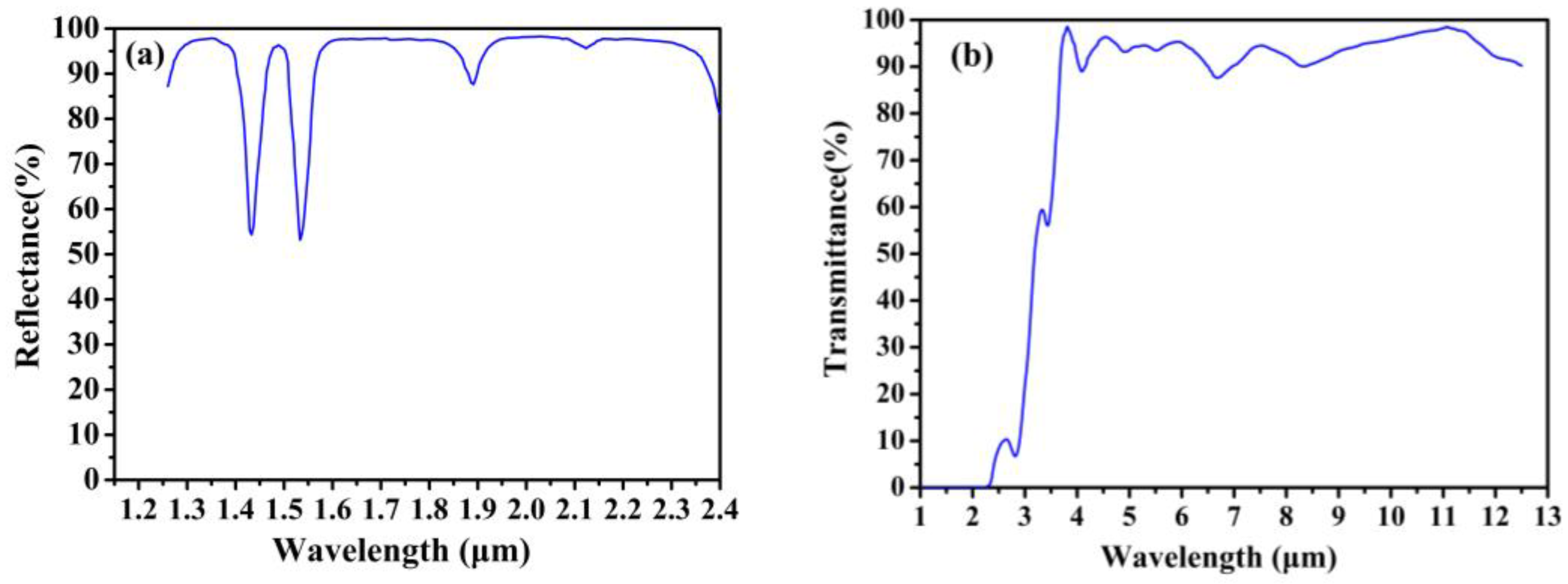
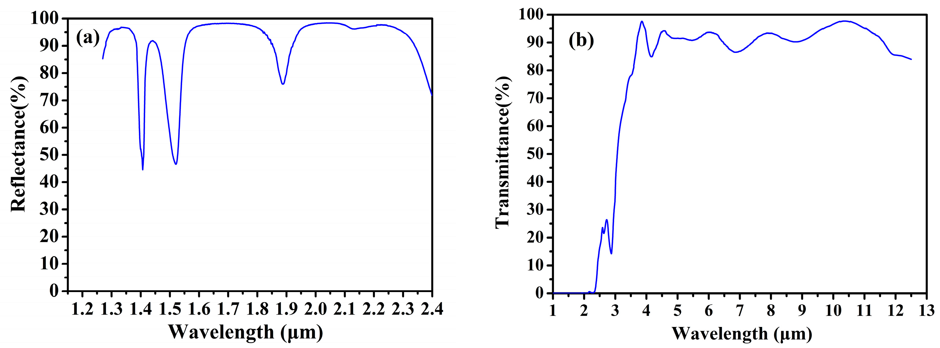
3. Results and Discussion
4. Conclusions
Author Contributions
Funding
Institutional Review Board Statement
Informed Consent Statement
Data Availability Statement
Conflicts of Interest
References
- Huang, L.Q.; Luo, R.C.; Liu, X.; Hao, X. Spectral imaging with deep learning. Light. Sci. Appl. 2022, 11, 61. [Google Scholar] [CrossRef] [PubMed]
- Kim, Y.; Ryu, H.S.; Hong, S. Data-to-data translation-based nowcasting of specific sea fog using geostationary weather satellite observation. Atmos. Res. 2023, 290, 106792. [Google Scholar] [CrossRef]
- Hawkins, G.; Sherwood, R.; Djotni, K.; Coppo, P.; Höhnemann, H.; Belli, F. Cooled infrared filters and dichroics for the sea and land surface temperature radiometer. Appl. Opt. 2013, 52, 2125–2135. [Google Scholar] [CrossRef]
- Kouli, M. Editorial for the special issue “Application of Satellite Remote Sensing in Solving Urban Geo-Environmental Issues”. Remote Sens. 2023, 15, 63. [Google Scholar] [CrossRef]
- Chen, H.; Xie, X.B.; Liu, E.Q.; Zhou, L.; Yan, L.J. Application of infrared remote sensing and magnetotelluric technology in geothermal resource exploration: A case study of the wuerhe area, Xinjiang. Remote Sens. 2021, 13, 4989. [Google Scholar] [CrossRef]
- Taquet, N.; Meza Hernández, I.; Stremme, W.; Bezanilla, A.; Grutter, M.; Campion, R.; Palm, M.; Boulesteix, T. Continuous measurements of SiF4 and SO2 by thermal emission spectroscopy: Insight from a 6-month survey at the Popocatépetl volcano. J. Volcanol. Geotherm. Res. 2017, 341, 255–268. [Google Scholar] [CrossRef]
- Shu, A.Q.; Shen, F.F.; Jiang, L.P.; Zhang, T.; Xu, D.M. Assimilation of Clear-sky FY-4A AGRI radiances within the WRFDA system for the prediction of a landfalling Typhoon Hagupit. Atmos. Res. 2023, 283, 106556. [Google Scholar] [CrossRef]
- Zhou, S.; Zhang, L.Y.; Guo, F.; Wu, C.F.; Xu, J.Q.; Zhang, K.F.; Li, K.; Liu, Z.; Xiao, X.G.; Song, S.G.; et al. Design and fabrication of an integrated dual-channel thin-film filter for the mid-infrared. Coatings 2021, 11, 803. [Google Scholar] [CrossRef]
- Duan, W.B.; Liu, B.J.; Zhuang, Q.H.; Jiang, L.; Li, D.Q.; Yu, D.M.; Qin, Y.; Ni, R.; Li, Y.P.; Zhou, S.; et al. Research Progress of infrared thin film coatings applied in space remote sensing systems. Acta Photon. Sin. 2022, 51, 0951601. [Google Scholar]
- Cao, J.J.; Chang, J.; Huang, S.; Wu, Y.N.; Ji, Z.Y.; Lai, X.X.; Wang, J.Y.; Li, Y.T.; Zhu, W.H.; Li, X.Y. Optical design and fabrication of a common-aperture multispectral imaging system for integrated deep space navigation and detection. Opt. Laser Eng. 2023, 167, 107169. [Google Scholar] [CrossRef]
- Mohamed, A.A.A.; Ahmed, M.; Shehata, M.; Almslmany, A. A novel dichroic beam splitters and sky cameras-based LIDAR receiver. In Proceedings of the IEEE International Telecommunications Conference (ITC-Egypt), Alexandria, Egypt, 13–15 July 2021; pp. 1–4. [Google Scholar]
- Mahendra, R.; Chandra, R. Dichroic beam splitter for visible, short-wave infrared, and mid-wave infrared. Opt. Eng. 2022, 61, 105111. [Google Scholar] [CrossRef]
- Rothhardt, C.; Birckigt, P.; Grabowski, K.; Risse, S.; Schlegel, R.; Shestaeva, S.; Schwinde, S.; Schmidl, S.; Klose, S. Realizing an all-glass beam splitter for space by using advanced joining technologies. Proc. SPIE 2022, 12777, 1277719. [Google Scholar]
- Li, H.R.; Yang, R.S.; Xie, L.Y.; Wei, Z.Y.; Zhang, J.L.; Wang, Z.S.; Cheng, X.B. Scattering characteristics of various nodular defects in a dichroic beam splitter. Opt. Express 2024, 32, 949–958. [Google Scholar] [CrossRef] [PubMed]
- Hendrix, K.; Kruschwitz, J.D.; Keck, J. Optical interference coatings design contest 2013: Angle-independent color mirror and shortwave infrared/mid-wave infrared dichroic beam splitters. Appl. Opt. 2014, 53, 360–374. [Google Scholar] [CrossRef] [PubMed]
- Upadhyaya, A.S.; Ghosh, A.; Bandyopadhyay, P.K. Short wave pass and long wave pass dichroic coating at 45° on zinc selenide substrate for dual band thermal imager. Infrared Phys. Technol. 2009, 52, 146–151. [Google Scholar] [CrossRef]
- Cao, J.; Jiang, B.B.; Jiao, H.F.; Niu, X.S.; Zhang, J.L.; Zhang, Z.; Chen, X.B.; Wang, Z.S. A dichroic beamsplitter for the laser protection of infrared detectors. Coatings 2022, 12, 1861. [Google Scholar] [CrossRef]
- Amotchkina, T.; Trubetskov, M.; Schulz, M.; Pervak, V. Comparative study of NIR-MIR beamsplitters based on ZnS/YbF3 and Ge/YbF3. Opt. Express 2019, 27, 5557–5569. [Google Scholar] [CrossRef] [PubMed]
- Jiang, L.; Qin, Y.; Cai, Q.Y.; Liu, D.Q.; Yu, T.Y. Study for low-polarization-sensitive dichroic mirrors to space remote sensing. Proc. SPIE 2022, 12169, 1216990. [Google Scholar]
- Yu, T.Y.; Liu, D.Q.; Qin, Y. The coatings for a solar-rejected window of the infrared horizon sensor. Infrared Phys. Technol. 2020, 105, 103214. [Google Scholar] [CrossRef]
- Stolberg-Rohr, T.; Hawkins, G.J. Spectral design of temperature-invariant narrow bandpass filters for the mid-infrared. Opt. Express 2015, 23, 580–596. [Google Scholar] [CrossRef]
- Liu, H.S.; Li, S.D.; Chen, D.; Yang, X.; He, J.H.; Jiang, Y.G.; Wang, L.S.; Liu, D.D.; Ji, Y.Q. Study on broadband optical constants of yttrium fluoride thin films deposited by electron beam evaporation. Optik 2020, 205, 163548. [Google Scholar] [CrossRef]
- Kumar, R.; Sonal, G.; Wajhal, S.; Satpati, S.K.; Sahu, M.L. Effect of process parameters on the recovery of thorium tetrafluoride prepared by hydrofluorination of thorium oxide, and their optimization. Nucl. Eng. Technol. 2022, 54, 1560–1569. [Google Scholar] [CrossRef]

| Number of Layers | Material | Thickness of Design (nm) |
|---|---|---|
| 1 | ZnS | 89.5 |
| 2 | Ge | 201.3 |
| 3 | ZnS | 281.2 |
| 4 | Ge | 106.4 |
| 5 | ZnS | 149.3 |
| 6 | YbF3 | 138.5 |
| 7 | ZnS | 521.6 |
| 8 | YbF3 | 975.9 |
| 9 | ZnS | 50.2 |
| Optical Properties | Angle of Inclination | B1 | B2 | B3 | B4 | B5 |
|---|---|---|---|---|---|---|
| Reflectance | 45° | 96% | 98% | 97.5% | ||
| Transmittance | 45° | 94% | 94.5% |
| Optical Properties | Angle of Inclination | C1 | C2 | C3 | C4 | C5 |
|---|---|---|---|---|---|---|
| Reflectance | 45° | 95% | 97% | 96.5% | ||
| Transmittance | 45° | 92% | 92% |
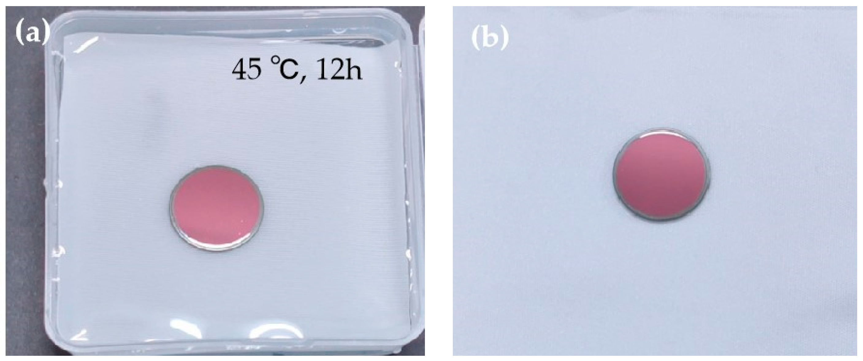
| Test Content | Temp. Humidity Test | Soaking Test | Adhesion Test | Temp. Alternating Test |
|---|---|---|---|---|
| Test conditions | 47 °C air humidity is 95%, maintained for 24 h | 45 °C for 12 h in a baking oven | rapid tearing adhesive tape size: 1 × 1 cm | −50 °C and 60 °C for 2 h; 3 times liquid nitrogen |
| Results | passed | passed | passed | passed |
Disclaimer/Publisher’s Note: The statements, opinions and data contained in all publications are solely those of the individual author(s) and contributor(s) and not of MDPI and/or the editor(s). MDPI and/or the editor(s) disclaim responsibility for any injury to people or property resulting from any ideas, methods, instructions or products referred to in the content. |
© 2024 by the authors. Licensee MDPI, Basel, Switzerland. This article is an open access article distributed under the terms and conditions of the Creative Commons Attribution (CC BY) license (https://creativecommons.org/licenses/by/4.0/).
Share and Cite
Jiang, L.; Qin, Y.; Yu, T.; Duan, W.; Liu, D. NIR to LWIR Dichroic Beamsplitter Designed and Manufactured for Space Optical Remote Sensor. Coatings 2024, 14, 235. https://doi.org/10.3390/coatings14020235
Jiang L, Qin Y, Yu T, Duan W, Liu D. NIR to LWIR Dichroic Beamsplitter Designed and Manufactured for Space Optical Remote Sensor. Coatings. 2024; 14(2):235. https://doi.org/10.3390/coatings14020235
Chicago/Turabian StyleJiang, Lin, Yang Qin, Tianyan Yu, Weibo Duan, and Dingquan Liu. 2024. "NIR to LWIR Dichroic Beamsplitter Designed and Manufactured for Space Optical Remote Sensor" Coatings 14, no. 2: 235. https://doi.org/10.3390/coatings14020235
APA StyleJiang, L., Qin, Y., Yu, T., Duan, W., & Liu, D. (2024). NIR to LWIR Dichroic Beamsplitter Designed and Manufactured for Space Optical Remote Sensor. Coatings, 14(2), 235. https://doi.org/10.3390/coatings14020235