Abstract
A Ti–Al alloy phase layer/Ti–Al carburizing composite coating was prepared on the surface of titanium alloy by the stepwise coating method of hot-dip aluminizing and then carburizing. The weight gain results of the composite coating showed that the titanium alloy coated with the composite coating had long-term stability (≥16 days) at 800 °C. The microstructure, phase structure, and composition of the composite coating were characterized by X-ray diffraction (XRD), scanning electron microscopy (SEM), and energy dispersive spectroscopy (EDS). The composite coating is composed of an alloy phase layer and a carburized layer. The natural transition of four phases (Ti3Al/TiAl/TiAl2/TiAl3) in the alloy phase layer significantly improves the interfacial bonding between the coating and the substrate and slows down the propagation of microcracks through the coating. Al2O3, TiC, and C in the carburizing layer improve the surface hardness of the coating, and TiAl2 and Al2O3 also have excellent oxidation resistance at high temperature.
1. Introduction
The aero-engine is known as the “heart” of aircraft, and the progress of its design, material, and manufacturing technology plays a key role in the development of the aviation industry. Advanced aero-engines are developing towards high turbine front temperatures, high thrust-to-weight ratios, long lifespans, and low fuel consumption. In addition to advanced design technology, the improvement of engine performance strongly depends on the development of advanced materials and manufacturing technology.
Titanium alloy, known as “space metal”, is widely used in the aerospace field because of its advantages, such as low density, high specific strength, corrosion resistance, and stable performance at low temperature [1,2,3,4]. However, titanium alloy’s poor high-temperature oxidation resistance [5], low surface hardness, high friction coefficient, and poor wear resistance seriously restrict its service life and application field [6]. In order to effectively improve the properties of titanium alloy, the most widely used method is to prepare aluminum coating with excellent oxidation resistance on the surface of titanium alloy.
The formation of a Ti–Al diffusion coating on titanium alloy is a common method to improve its high-temperature oxidation resistance [7,8]. The Ti–Al diffused coating can be prepared by different processes, such as thermal spraying [9], aluminizing [10], laser surface alloying [11], the sol-gel method [12], and hot-dip aluminizing [7]. For example, Li, Z.W. et al. prepared Ti3Al (O)-Al2O3 composite coating on the surface of titanium alloy by thermal spraying. The composite coating showed good oxidation resistance and excellent spalling resistance in the temperature range of 700~900 °C. Chen, Y. et al. prepared a Ti–Ni alloy composite coating on the surface of Ti-6Al-4V by laser surface modification. By adjusting the process parameters, different combinations of ductile TiNi and hard Ti2Ni intermetallic phases can be synthesized on the Ti-6Al-4V surface to obtain adjustable surface properties. Hot-dip aluminizing is a mature and extensible process [13,14]. Wang, Z. et al. [14] prepared a Ti–Al–Si gradient coating based on silicon concentration gradients and added Ce to modify the coating. The coating has a dense Ti(Al,Si)3 phase layer, which can effectively improve the high-temperature oxidation resistance of titanium alloys. The addition of cerium can effectively inhibit the formation of the τ2: Ti(AlxSi1−x)2 phase in a certain heat infiltration time, so as to form a continuous dense Al2O3 layer, and further improve the oxidation resistance of the coating. The hot-dip aluminizing process includes surface pretreatment of the sample and holding in a molten aluminum pool for a certain time. This method was first applied to stainless steel, carbon steel, and alloy steel, and is often used to improve the corrosion resistance, wear resistance, and high-temperature oxidation resistance [15,16,17]. TiAl3 phase +L-(Ti,Al) and L-(Ti,Al) layers are formed on the surface of titanium alloy after hot-dip aluminizing. Due to the brittleness of TiAl3 phase and the mismatch of thermal expansion coefficients between TiAl3 phase and titanium alloy substrate [18], the mechanical properties of the substrate are reduced and cracks are easy to propagate. Therefore, proper heat treatment is required after hot-dip aluminizing to make elements diffuse between the coating and substrate, so as to produce metallurgical bonding between the coating and substrate [19]. The L-(Ti,Al) layer on the surface is mainly aluminum, and its wear resistance and hardness are insufficient. Surface modification of the L-(Ti,Al) layer to improve its wear resistance and surface hardness and reduce its friction coefficient is an urgent requirement to improve its application in various fields.
In the process of carburizing, carbon atoms penetrate into the surface of titanium alloy through a concentration gradient at a high temperature to form the corresponding carbide (TiC) gradient coating. The advantage of carburizing on titanium alloy is to effectively improve the surface hardness and wear resistance of the material without changing the substrate properties and macroscopic size. For example, Duan, H.q. et al. adopted solid carburizing technology to improve the hardness of Ti-6Al-4V alloy and (TiB + La2O3)/Ti composite [20]. They used graphite powder as a carbon source, avoiding hydrogen embrittlement. The gradient structure coating is grown by in situ extension, which significantly improves the interface bonding between the coating and the substrate and eliminates the mismatch of the thermal expansion coefficient and weak adhesion [21]. However, the thickness of the coating prepared by this method is limited, generally only a few microns to tens of microns.
We combine the hot-dip aluminizing process with the carburizing process to give full play to the advantages of both and achieve the optimization effect of “1 + 1 > 2”. When the titanium alloy after hot-dip aluminizing is carburizing, the surface L-(Ti,Al) layer reacts with active carbon atoms to form a Ti–Al carburizing layer with good wear resistance and high hardness. The aluminum element in the TiAl3 phase continues to diffuse to the substrate, and Al reacts with Ti to form more Ti–Al alloy phase layers. Finally, the Ti–Al alloy phase layer/Ti–Al carburizing layer composite coating is formed. The composite coating has the advantages of close bonding with the substrate and excellent oxidation resistance at high temperatures.
In this paper, we studied the process of hot-dip aluminizing and carburizing of Ti65 samples and analyzed the high temperature and oxidation resistance of the obtained samples. We studied the microstructure and growth kinetics of the coating before and after thermal exposure tests. The internal reasons for the excellent high temperature and oxidation resistance of titanium alloy after hot-dip aluminizing and carburizing were discussed.
2. Materials and Methods
2.1. Experimental Material
High purity aluminum ingots (99.999%, Nantong Taide electronic Material Technology Co., Ltd., Rugao City, China), carburizing agents (C, NaCO3, BaCO3, CaCO3) (Changge Tanerno catalytic Technology Co., Ltd., Changge City, China and Sinopharm Group Chemical reagent Co., Ltd., Shanghai, China), and Ti65 alloy (Dongguan Xinrui Metal material Co., Ltd., Dongguan City, China) were selected in the experiment. The composition of Ti65 alloy is shown in Table 1. The sample was linearly cut to 15 mm (length) × 10 mm (width) × 3 mm (thickness). All samples were polished with 400#, 600#, and 800# sandpaper to ensure a smooth surface.

Table 1.
The composition of Ti65 alloy.
2.2. Hot-Dip Aluminizing
After several Ti65 samples were cleaned with acetone for 5 min, washed with water, and cleaned with alcohol for 15 min, they were immersed in pure aluminum liquid protected by argon at 760 °C for 5 min, 10 min, 15 min, and 20 min, respectively. Then, the Ti65 samples were slowly extracted and the excess aluminum liquid on their surface was removed.
2.3. Carburization
The hot-dip-aluminized Ti65 samples were placed in a corundum crucible equipped with a solid carburizing agent and sealed with a mixture of calcined kaolin and sodium silicate. Then, the sealed crucible was dried in an oven for 2 h and then put into a box-type resistance furnace (Xiangtan Samsung Instrument Co., Ltd., Xiangtan, China) for carburizing. The samples were kept at 1050 °C for 2 h, 4 h, 6 h, and 8 h, respectively, and then removed after cooling to room temperature in the furnace.
2.4. Characterization Test
The phase of the coating was analyzed by X-ray diffraction (XRD) using an Ultima IV (Ultima IV, Rigaku Co., Tokyo, Japan) diffractometer with Cu Ka radiation (λ = 0.15406 nm). The working voltage of the X-ray tube was 40 kV and the working current was 40 mA, and the XRD spectra obtained were in the range of 10°–90°. The angle step was 0.02° and the scanning speed was 10°min−1.
Scanning electron microscopy (SEM) (ZEISS EVO MA10, ZEISS, Jena, Germany) and energy dispersion spectroscopy (EDS) (OXFORD X-MAXN, ZEISS, Jena, Germany) systems were used for the analysis of the coating morphology and element distribution.
The hardness of the uncoated Ti65 sample, the hot-dip-aluminized (760 °C × 10 min) Ti65 sample, and the hot-dip-aluminized (760 °C × 10 min) and carburized (1050 °C × 4 h) Ti65 sample was measured using a hardness tester (SHYCHVT-30, Laizhou Huayin Hardness Meter Factory, Lai Zhou, China). These samples were observed under the Vickers hardness tester microscope and the samples were measured three times; the macro hardness value was obtained by taking the average value. The penetrator type was a diamond cone penetrator with a force of 3 kg and a load holding time of 10 s.
2.5. Thermal Exposure Test
For comparison, uncoated Ti65 samples, hot-dip-aluminized (760 °C × 10 min) Ti65 samples, and hot-dip-aluminized (760 °C × 10 min) and carburized (1050 °C × 4 h) Ti65 samples (represented by group A, B and C below) were placed in static air at 800 °C at the same time for the thermal exposure test. The duration varied from 2 to 16 days, with 2 day intervals, and 3 samples were consumed for each thermal exposure time. Before and after the thermal exposure test, an electronic balance was used to weigh and record (the measurement accuracy of weight is ±10−4 g), so as to calculate the weight gain per unit area of the sample at different times and obtain the high-temperature oxidation weight gain curve. The microstructure, phase composition, and element distribution of the coating were studied by X-ray diffractometry (XRD), scanning electron microscopy (SEM), and energy dispersive spectroscopy (EDS).
3. Results and Discussion
3.1. Characterization of the Coating Microstructure
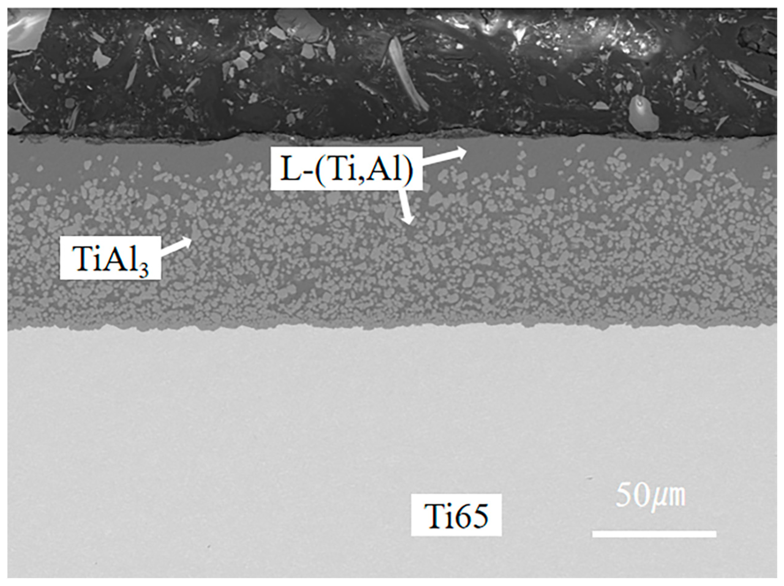
3.1.1. Microstructure of the Hot-Dip Aluminizing Coating
We found that the TiAl3 phase layer can be formed by hot-dip aluminizing at 760 °C for 5–20 min, but its thickness is different. When the hot-dip aluminizing time is less than 10 min, the thickness of the TiAl3 phase layer is low, which is not conducive to the formation of an appropriate thickness Ti–Al alloy phase layer in the subsequent carburizing process, while the hot-dip aluminizing time is too long, which is not suitable for industrial production and is more likely to lead to the generation and expansion of micro-cracks in the TiAl3 phase layer. Therefore, we chose to analyze the structure and properties of the coating obtained by hot-dip aluminizing for 10 min. Figure 1 shows the microstructure of Ti65 after 10 min of hot-dip aluminizing.
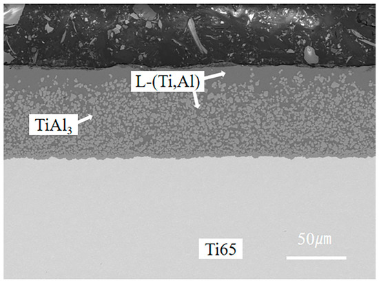
Figure 1.
Microstructure after hot-dip aluminizing at 760 °C for 10 min.
We found that three new Ti–Al alloy phase layers (Ti3Al, TiAl, TiAl2) can be formed by carburizing at 1050 °C for 2 to 4 h, but the thickness is different, and the Ti–Al carburizing layer contains Al2O3, TiAl2, C, and TiC. When the carburizing time is less than 4 h, the thickness of the Ti–Al carburizing layer and the three Ti–Al alloy phase layers (TiAl2, TiAl, Ti3Al) is small. When the carburizing time is too long, the surface brittleness of the coating increases, and the carburizing layer is easy to peel off. Therefore, we chose to analyze the structure and properties of the coating obtained by carburizing for 4 h.
3.1.2. Microstructure of the Composite Coating
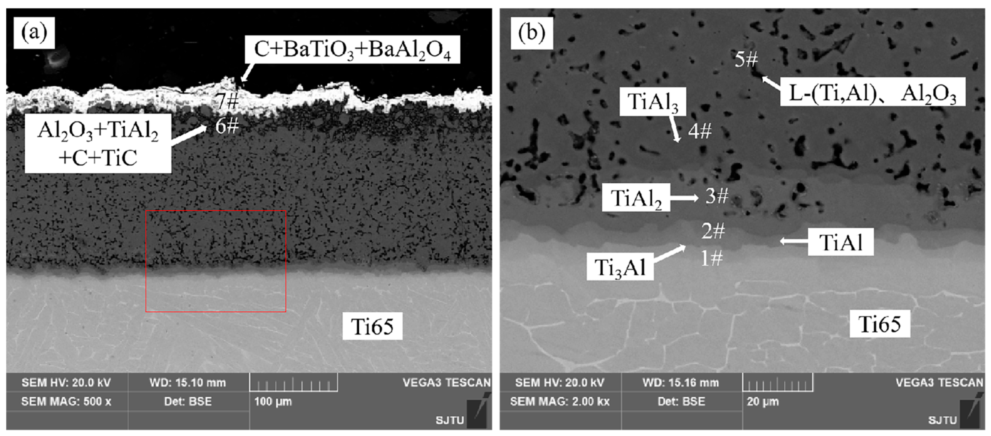
Figure 2 shows the cross-section microstructure of the Ti–Al alloy phase layer/Ti–Al carburizing composite coating obtained by hot-dip aluminizing (760 °C × 10 min) and carburizing (1050 °C × 4 h). It can be observed that the coating has obvious stratification, consisting of two regions: one is the alloying phase layer region and the other is the carburizing layer region.

Figure 2.
(a) Cross section microstructure of the composite coating obtained by hot-dip aluminizing (760 °C × 10 min) and carburizing (1050 °C × 4 h); (b) Enlarged part of the red wire frame in (a). The 1#-7# are the EDS point scan location.
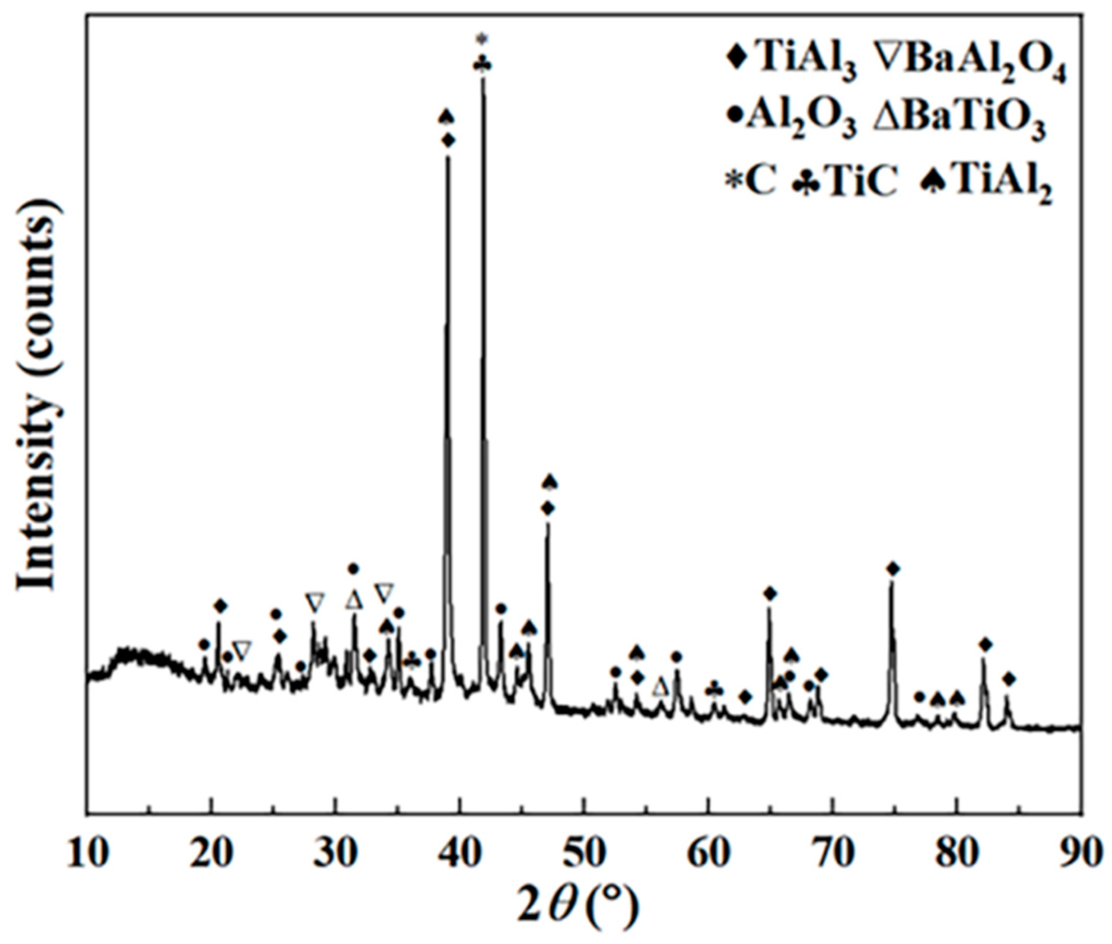
EDS data of different regions are shown in Table 2. EDS data of the alloy phase layer region indicate that four Ti–Al diffusion layers are formed between the coating and substrate. In addition, some voids were observed in the coating. The atomic ratios of Ti and Al at positions 1, 2, 3, and 4 are 3:1, 1:1, 1:2, and 1:3, respectively. Combined with the XRD pattern shown in Figure 3, the four phases are Ti3Al, TiAl, TiAl2, and TiAl3, respectively.
Table 2.
EDS data (at.%) and phase composition in different regions.
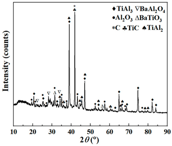
Figure 3.
XRD pattern of the composite coating obtained by hot-dip aluminizing (760 °C × 10 min) and carburizing (1050 °C × 4 h).
One of the causes of the holes in the coating is the Kirkendall effect. Al [22] in TiAl3 diffuses with Ti in the substrate, and the diffusion rate of Al is much higher than that of Ti [23], so the net diffusion is manifested as Al in TiAl3 diffusing into the Ti65 substrate, resulting in the vacancy at the edge of the TiAl3 phase [24,25]. The accumulation of vacancy leads to the formation of the Kirkendall void [26]. Another reason is the brittleness and large thermal expansion coefficient of TiAl3 phase, which leads to the formation of cavities in the cooling process [27].
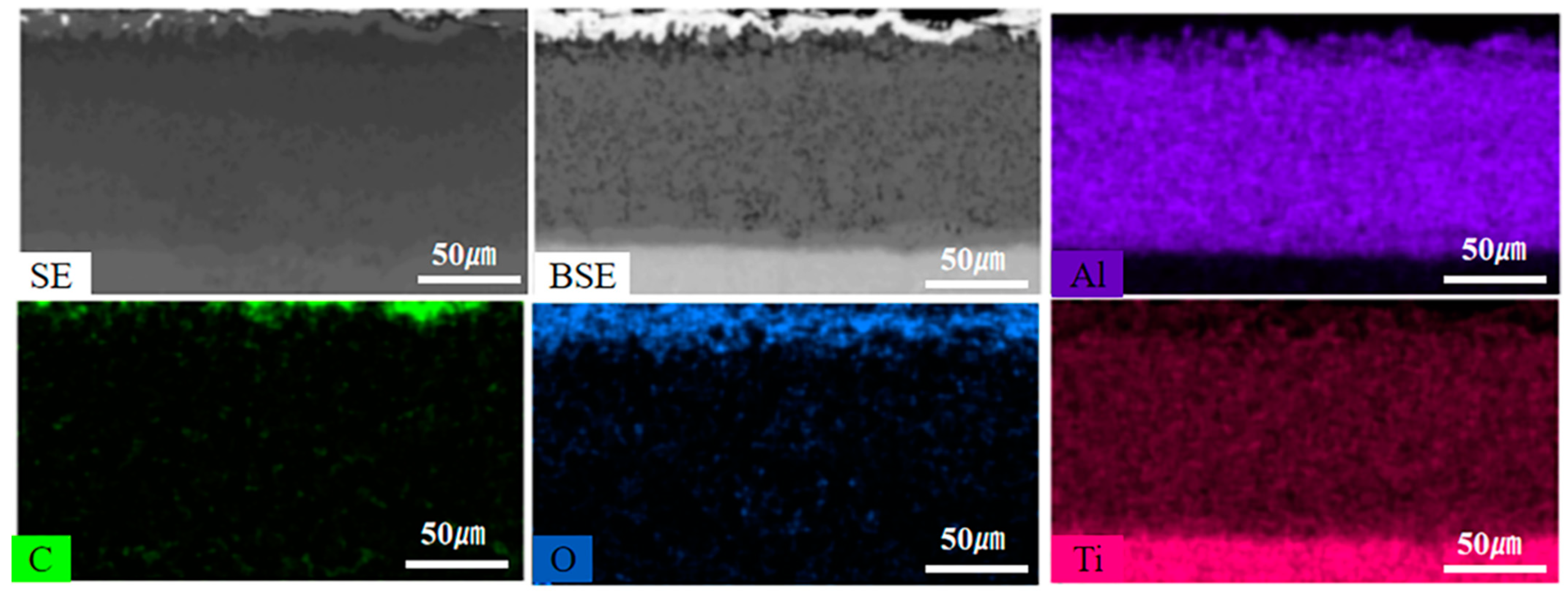
Figure 4 shows that C and O elements are mainly distributed in the carburized layer. EDS results and XRD patterns of the carburized layer indicate that the region is composed of Al2O3, TiAl2, TiC, and free C. In Figure 2a, the white part at the top of the coating is BaAl2O4, BaTiO3, and free C. The BaAl2O4 phase and BaTiO3 phase are generated by the reaction of the energizer BaCO3 with Al and Ti atoms in the process of carburizing, while the free C is formed by the carbon in the carburizing agent remaining in the sag on the surface of the sample.
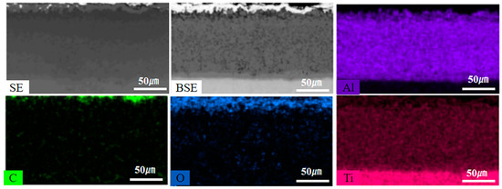
Figure 4.
EDS element maps of the composite coating obtained by hot-dip aluminizing (760 °C × 10 min) and carburizing (1050 °C × 4 h).
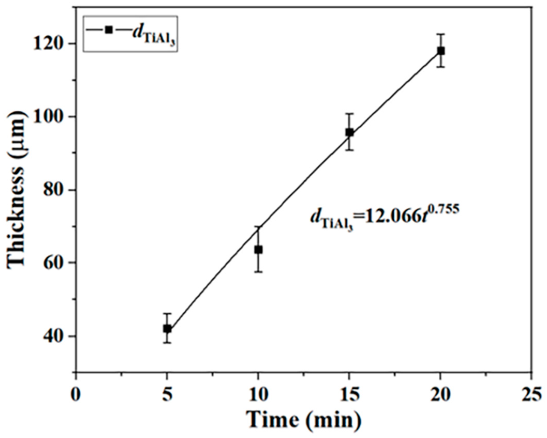
3.1.3. Growth Kinetics of the TiAl3 Phase
After hot-dip aluminizing, the coating formed on the surface of the Ti65 sample is composed of the TiAl3 phase +L-(Ti,Al) and L-(Ti,Al) layer. The relationship between the thickness and time of the TiAl3 phase can be expressed by the empirical formula [28,29]:
where d is the thickness of the TiAl3 phase (μm), t is the hot-dip aluminizing time (min), k is the rate constant, and n is the kinetic index. Kinetic index values of n < 0.5 represent diffusion-controlled growth, while values of n > 0.5 represent reaction-controlled growth.
d = ktn
The thickness of the TiAl3 phase is represented by dTiAl, and the growth kinetics curve of the TiAl3 phase was fitted by Equation (1), as shown in Figure 5:
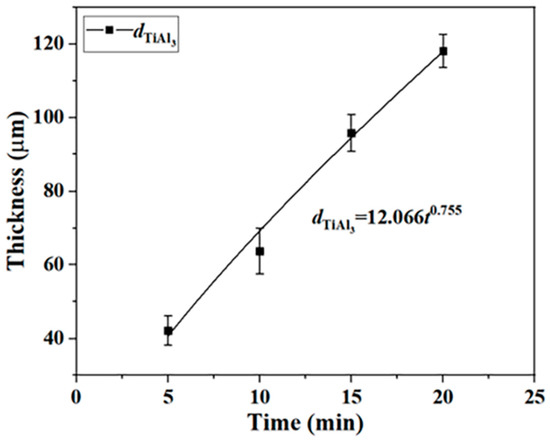
Figure 5.
Growth kinetics curve of the TiAl3 phase.
The results show that the growth of the TiAl3 phase is reaction-controlled growth.
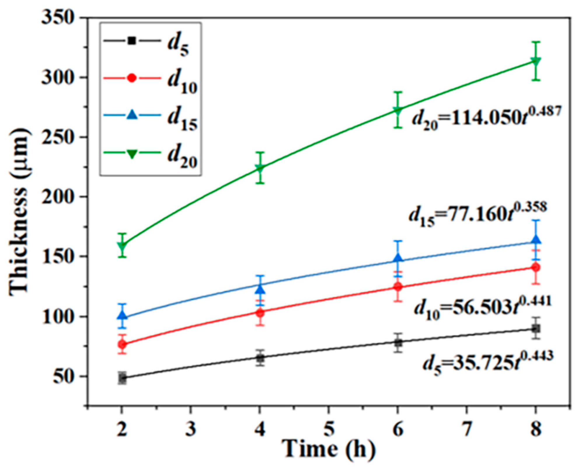
3.1.4. Growth Kinetics of the Ti–Al Alloy Phase Layer
d5, d10, d15, and d20 are used to represent the thickness of the Ti–Al alloy phase layer in the process of carburizing after 5 min, 10 min, 15 min, and 20 min of hot-dip aluminizing, respectively. The growth kinetics curve of the Ti–Al alloy phase layer was fitted by Formula (1), as shown in Figure 6:
d5 = 35.725t0.443
d10 = 56.503t0.441
d15 = 76.160t0.358
d20 = 114.050t0.487
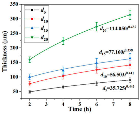
Figure 6.
Growth kinetics curves of the Ti–Al alloy phase layers in the process of carburizing under different hot-dip aluminizing times.
The results show that the growth of the Ti–Al alloy phase layer is controlled by diffusion.
3.1.5. Formation Mechanism of the Composite Coating
During hot-dip aluminizing of titanium alloy, the liquid aluminum and the base metal interdiffuse and the TiAl3 phase is formed on the titanium alloy. The diffusion reaction is
Ti + 3Al → TiAl3
Since the titanium atoms in the substrate diffuse into the liquid aluminum, which contains titanium atoms, and there are voids in the TiAl3 phase, the liquid aluminum-containing titanium atoms will partially fill the voids around TiAl3 during hot-dip aluminizing, forming a mixed-phase layer composed of the TiAl3 phase and the L-(Ti,Al) phase. When the titanium alloy sample is extracted from the aluminum pool, the liquid aluminum-containing titanium atoms will adhere to the outside of the mixed-phase layer and solidify into the outermost layer of the hot-dip-aluminized coating. Therefore, the coating after hot-dip aluminizing is composed of a TiAl3 phase +L-(Ti,Al) mixed-phase layer and a L-(Ti,Al) layer.
When the hot-dip-aluminized Ti65 sample is carburized, the aluminum element in the TiAl3 phase continues to diffuse to the substrate, while the Ti element in the substrate diffuses to the coating. During the diffusion process, Al and Ti react to form three Ti–Al alloy layers (Ti3Al, TiAl, and TiAl2). Kattner et al. calculated the Gibbs free energy of the three products as follows:
ΔGf (TiAl2) = −43858.4 + 11.02077T (K)
ΔGf (TiAl) = −37445.1 + 16.79376T (K)
ΔGf (Ti3Al) = −29633.6 + 6.70801T (K)
At 1050 °C, the Gibbs free energy of the three phases is less than zero, namely, ΔGf < 0, indicating that the three compounds can be formed thermodynamically. The formation process of the alloy phase layer is
2TiAl3 + 4Ti → Ti3Al + TiAl + 2TiAl2
The natural transition of the three newly formed phases (Ti3Al, TiAl, and TiAl2) and TiAl3 not only ensures the high-temperature oxidation resistance of the composite coating, but also enhances the interface bonding between the coating and the substrate and slows down the propagation of microcracks through the coating.
The surface L-(Ti,Al) layer reacts with active carbon atoms to form a Ti–Al carburizing layer, and finally forms a Ti–Al alloy phase layer/Ti–Al carburizing layer composite coating.
The residual small amount of O2 in the corundum crucible will cause the incomplete combustion of C to produce CO, and the energizer BaCO3 will also produce CO during the decomposition process. Because there is a certain carbon concentration gradient and oxygen concentration gradient between the surface layer and the inner layer of the coating, the temperature is relatively high, and the thermal vibration of the atoms is relatively severe, CO, C, and O2 will continue to diffuse inward through the L-(Ti,Al) layer, and the following reactions will occur in the L-(Ti,Al) layer and at the interface between it and the TiAl3 phase:
4Al + 3O2 → 2Al2O3
Ti + C → TiC
2TiAl3 + 3CO → Al2O3 + 2TiAl2 + 3C
The newly generated C and the C diffused from the carburizing agent will be polarized at the crystal defects with disordered atomic arrangements, such as those at the boundary, the grain boundary, and the dislocation of the L-(Ti,Al) layer and the TiAl3 phase, thus further distorting the interface, dislocation, and other defects. These distortion regions will become the rapid diffusion channels of CO, C, and O2. The Al in the L-(Ti,Al) layer is further oxidized into a continuous dense Al2O3 layer distributed in the Ti–Al carburizing layer outside the TiAl3 phase, and TiAl3 is further consumed to produce Al2O3 and TiAl2. Since the Ti content in the L-(Ti,Al) layer is low and dispersing in Al, TiC generated during carburizing process will disperse in Ti–Al carburizing layer.
In the process of carburizing, the energizer BaCO3 will react with Al and Ti atoms in the L-(Ti,Al) layer to form BaAl2O4 and BaTiO3 at the top layer of the sample. The reaction may be
2BaCO3 + Ti + 2Al + O2 → BaAl2O4 + BaTiO3 + C + CO
3.2. High-Temperature Oxidation Resistance of the Coating
3.2.1. Microstructure of Composite Coatings after the Thermal Exposure Test
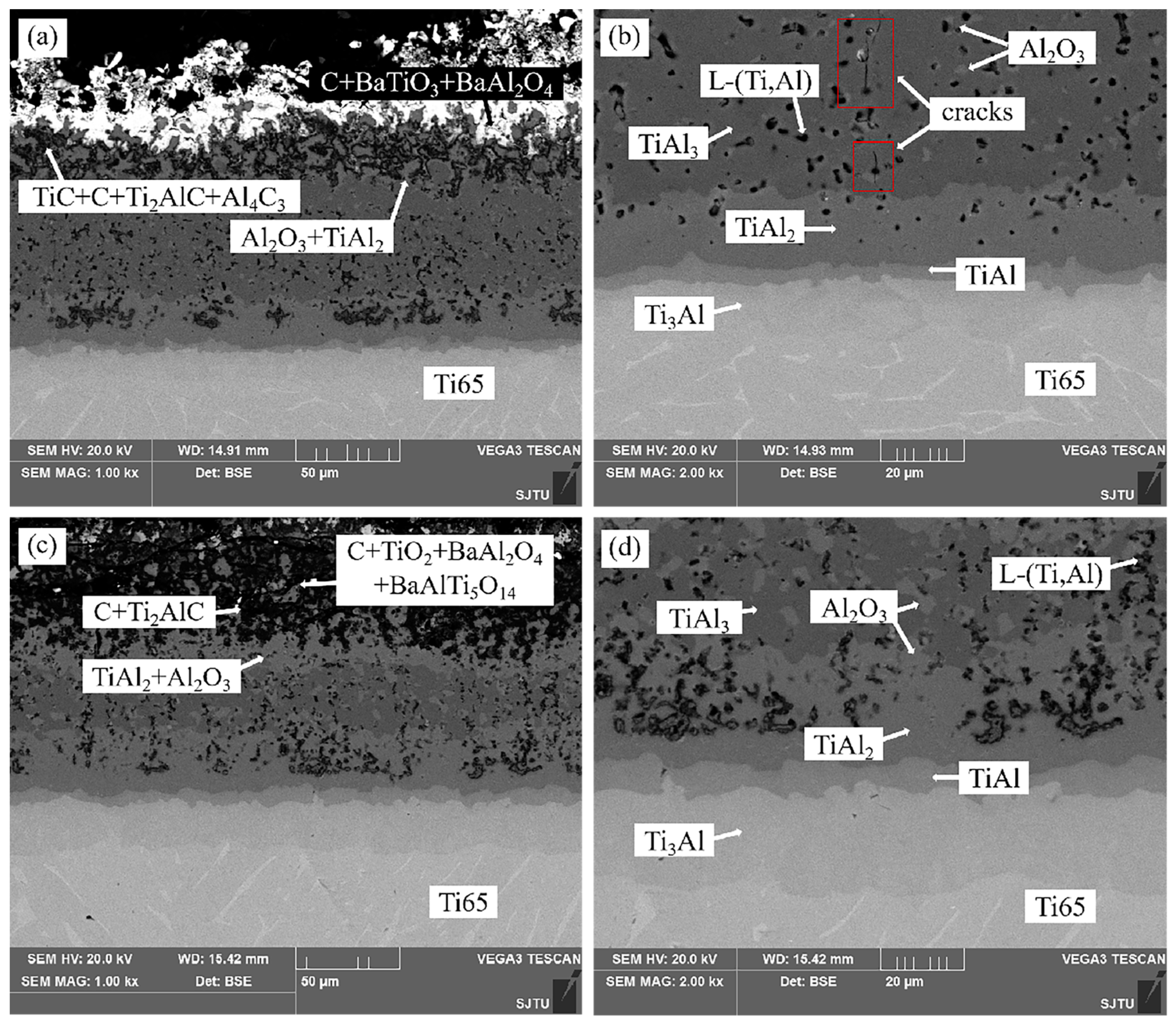
The interfacial reaction of the composite coating in the thermal exposure test is studied by observing the cross-section morphology, EDS pattern, and XRD pattern of the hot-dip-aluminized (760 °C × 10 min) and carburized (1050 °C × 4 h) Ti65 samples after different thermal exposure times. Figure 7 shows the sectional morphology of the composite coating obtained by hot-dip aluminizing (760 °C × 10 min) and carburizing (1050 °C × 4 h) after thermal exposure to static air at 800 °C for 2 days and 16 days. After the thermal exposure test, micro-cracks appear in the coating [30]. As can be seen from Figure 7b, micro-cracks do not penetrate the entire coating, but mainly distribute in the TiAl3 phase layer with the largest thickness. This is because the natural transition of the four Ti–Al alloy phase layers significantly improves the interface bonding between the coating and the substrate and slows down the further propagation of microcracks through the coating.

Figure 7.
(a) Composite coating obtained by hot-dip aluminizing (760 °C × 10 min) and carburizing (1050 °C × 4 h); (a) Microstructure of the sample that was thermally exposed for 2 days; (b) Microstructure of the 2-day alloy phase layer by heat exposure; (c) Microstructure of the sample that was thermally exposed for 16 days; (d) Microstructure of the 16-day alloy phase layer by heat exposure. The red frames in the (b) indicate the size and distribution of the cracks.
By comparing Figure 7d with Figure 2b, it can be found that the thickness of the Ti3Al, TiAl, and TiAl2 phases increases after the thermal exposure test, while the thickness of the TiAl3 phase decreases. The portion of L-(Ti,Al) around the TiAl3 phase is oxidized into Al2O3 and distributed between the TiAl3 phase and L-(Ti,Al). The Al2O3 content of samples under heat exposure for 2 days is small and distributed outside L-(Ti,Al) in a fine network, while the Al2O3 content of samples under heat exposure for 16 days is massive and significantly more than that shown by residual heat exposure for 2 days. Due to the increase in Ti content, L-(Ti,Al) near the TiAl2 phase has enough Ti atomic weight to react with Al in the TiAl2 phase to form TiAl2. Therefore, a mixed-phase layer of TiAl2 and Al2O3 appears in the upper part of the TiAl2 phase. After 16 days of thermal exposure, a relatively continuous and dense TiAl2 and Al2O3 layer was formed above the TiAl3 phase layer. These changes in thermal exposure tests can effectively prevent oxygen from entering the substrate.
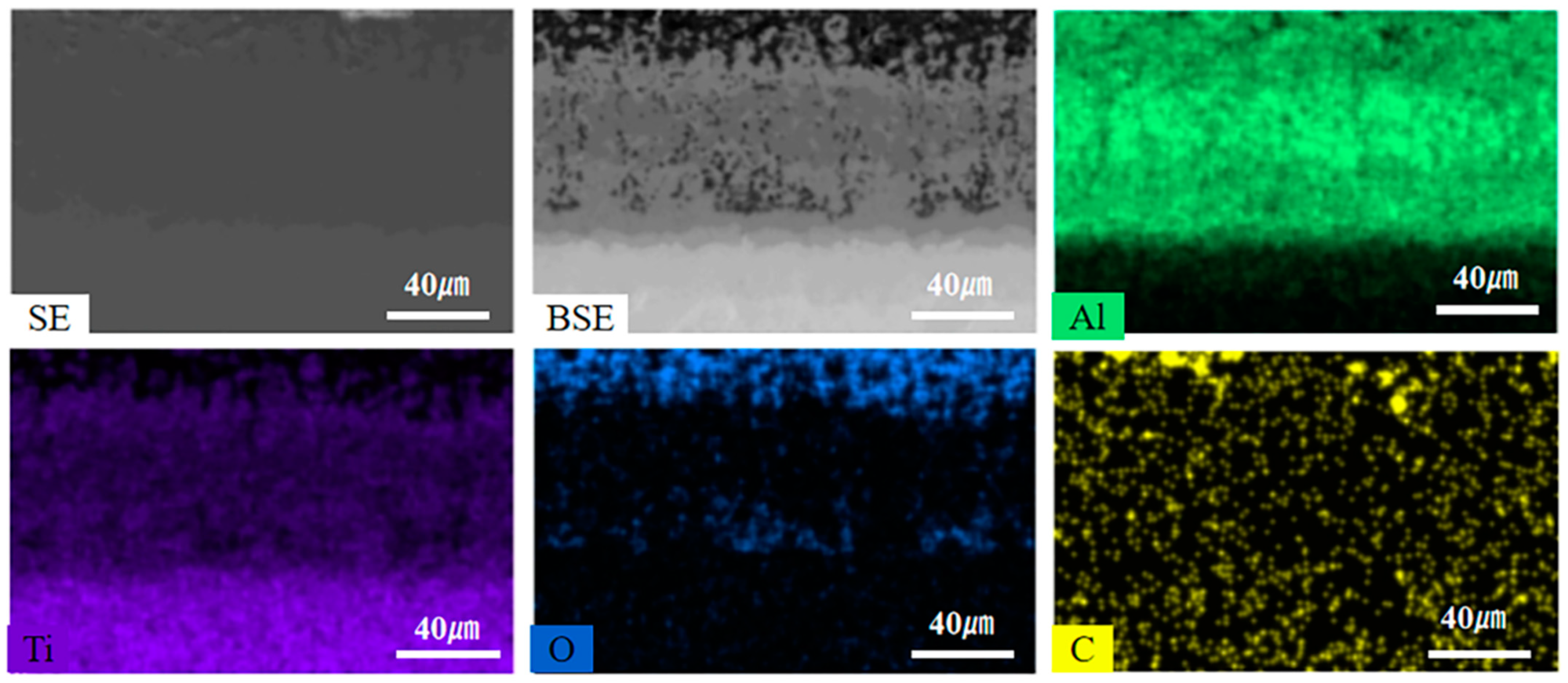
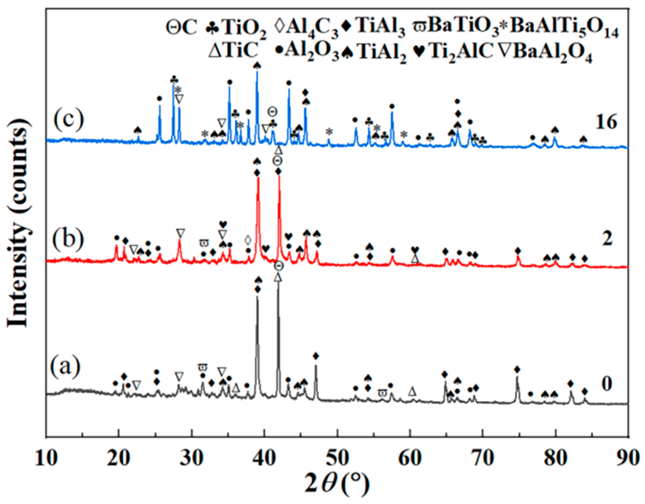
Figure 8 shows the EDS element maps of the composite coating after 16 days of thermal exposure. The results show that the oxygen content from the coating surface to the substrate shows a decreasing trend and that oxygen is mainly distributed in the Ti–Al carbon layer. Therefore, the composite coating can effectively prevent oxygen from entering the substrate and protect the substrate from oxidation for a long time at 800 °C. Figure 9a–c are XRD patterns before thermal exposure testing for 2 days and for 16 days, respectively. Figure 9b adds Ti2AlC and Al4C3 compared with Figure 9a. In Figure 9c, compared with Figure 9b, the contents of TiAl3, C, and Ti2AlC decrease, while Al4C3, TiC, and BaTiO3 disappear, and TiO2 and BaAlTi5O14 appear.

Figure 8.
EDS element maps of the composite coating obtained by hot-dip aluminizing (760 °C × 10 min) and carburizing (1050 °C × 4 h) after thermal exposure for 16 days in 800 °C air.

Figure 9.
XRD pattern of composite coating obtained by hot-dip aluminizing (760 °C × 10 min) and carburizing (1050 °C × 4 h): (a) before thermal exposure, (b) after thermal exposure for 2 days, (c) after thermal exposure for 16 days.
3.2.2. High-Temperature Oxidation Weight Gain Curve
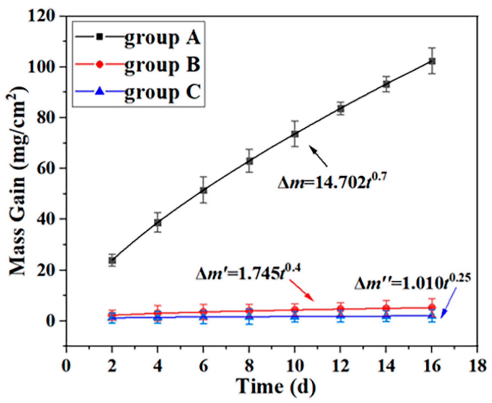
Figure 10 shows the oxidation kinetics curves of the uncoated Ti65 sample, the hot-dip-aluminized (760 °C × 10 min) Ti65 sample, and the hot-dip-aluminized (760 °C × 10 min) and carburized (1050 °C × 4 h) Ti65 sample (represented by groups A, B, and C below) in the air at 800 °C. The weight of all samples increased with the increase in thermal exposure time, and the weight of group A was significantly higher than that of group B or C.
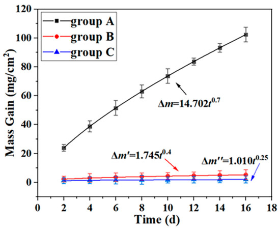
Figure 10.
Oxidation kinetics curves of group A, B, and C samples in 800 °C air.
The oxidation kinetics curve of group A samples can be fitted as follows:
where Δm is the oxidation weight gain (mg/cm2) of group A samples and t is the oxidation time (days).
Δm = 14.702t0.7
The oxidation kinetics curve of group B samples can be fitted as follows:
where Δm′ is the oxidation weight gain (mg/cm2) of group B samples and t is the oxidation time (days).
Δm′ = 1.745t0.4
The oxidation kinetics curve of group C samples can be fitted as follows:
where Δm″ is the oxidation weight gain (mg/cm2) of group C samples and t is the oxidation time (days).
Δm″ = 1.010t0.25
The oxidation of group A samples, namely uncoated Ti65 substrate samples, is the most serious, indicating that the oxidation layer [5] (mainly TiO2) of uncoated Ti65 substrate samples cannot inhibit the further oxidation of the substrate at 800 °C. After 16 days of thermal exposure, the weight gain of group A was 102.390 mg/cm2, that of group B was 5.29 mg/cm2, and that of group C was 2.044 mg/cm2. The oxidation weight gain of group A is about 50 times that of group C, and the oxidation weight gain of group B is about 2.6 times that of group C, which means that the composite coating significantly improves the oxidation resistance of Ti65 alloy at high temperature.
In the process of thermal exposure testing of group A samples, a large amount of oxide peel was shed [5], while in the whole process of thermal exposure testing of group B samples, no oxide peel was shed and the surface of group B was kept smooth; in the process of thermal exposure testing of group C samples, no obvious oxide peel was shed, but white spot-like substances appeared on the coating surface. One of the reasons for the peeling of oxide skin is that the TiO2-rich oxide skin formed at 800 °C has a loose structure and weak adhesion with the substrate. Another reason is the mismatch of thermal expansion coefficients between the oxide layer and the substrate.
Ebach-Stahl, A. et al. deposited intermetallic Ti–Al–Cr–Y coatings on the surface of Ti-17 and Ti-6242 titanium alloys by magnetron sputtering technology. The adhesion of the coating to the substrate was good. Compared with the bare substrate material, the mass gain of the coated sample was significantly reduced at 600 °C and 700 °C exposure, indicating that the Ti–Al–Cr–Y layer has a higher oxidation resistance [31]. Zhao, P. et al. prepared an AlNbTaZrx high-entropy alloy coating by laser cladding technology in Ti6Al4V, which improved the wear resistance and high-temperature oxidation resistance [32].
3.2.3. Mechanism of Oxidation Resistance at High Temperature
The process of thermal exposure is also a process of atomic diffusion. At high temperatures, atomic diffusion intensifies, and each element diffuses in the direction of the decreasing concentration gradient. For example, Al, O, and C elements diffuse to the inner layer and Ti elements diffuse to the outer layer. Ti2AlC and Al4C3 appeared in the coating after 2 days of thermal exposure, indicating that the binding energy of Ti2AlC and Al4C3 is large; this diffusion cannot occur during the 4 h carburizing process. It can form under the condition of high temperature and sufficient time only after sufficient energy is obtained. The formation process can be expressed as:
2Ti + Al + C → Ti2AlC
4Al + 3C → Al4C3
With the increase in thermal exposure time, oxygen continues to diffuse inward. The oxygen reacts with the residual carbon in the depression of the coating surface to produce CO2 and then reacts with the osmotic agent products BaAl2O4 and BaTiO3. The Ti atom in the Ti–Al carburizing layer diffuses outwards and is oxidized by oxygen into TiO2. TiO2 and the oxidation products of BaAl2O4 and BaTiO3 form the mixture BaAlTi5O14. The reaction equation of this interface may be
C + O2 → CO2
Ti + O2 → TiO2
BaTiO3 + BaAl2O4 + 2Al + 9TiO2 + 3O2 → 2BaAlTi5O14 + Al2O3
Then, oxygen will enter the Ti-Al carburizing layer, continue to react with the unoxidized Al in the carburizing process, and react with Ti [5] atoms, TiC [33], Ti2AlC [34], and Al4C3 [35]. At the same time, TiC [36] will react with Al and Ti. The reaction equation of this interface may be
Ti + O2 → TiO2
4Al + 3O2 → 2Al2O3
TiC + 2O2 → TiO2 + CO2
4Ti2AlC + 15O2 → 8TiO2 + 4CO2 +2Al2O3
Al4C3 + 6O2 → 2Al2O3 + 3CO2
TiC + Ti + Al → Ti2AlC
The structure of TiO2 generated by oxidation in the Ti–Al carburizing layer is loose, and the escape of CO2 will leave a void in the layer. The occurrence of these defects will destroy the continuity of the Al2O3 phase layer and promote the further inward diffusion of oxygen. After 16 days of thermal exposure, the contents of C and Ti2AlC are reduced due to oxidation, TiC is oxidized to TiO2 and converts to Ti2AlC, and Al4C3 is completely oxidized and disappears.
When oxygen passes through the Ti–Al carburizing layer to the TiAl3 phase layer, it will react with TiAl3, and the resulting oxidation products will form a relatively continuous and dense TiAl2 and Al2O3 phase layer distributed on the interface between the TiAl3 phase layer and Ti–Al carburizing layer [37]. The reaction is as follows:
4TiAl3 + 3O2 → 4TiAl2 + 2Al2O3
Oxygen penetrating into the TiAl3 phase layer will react preferentially with Al atoms in L-(Ti,Al) around the TiAl3 phase to generate Al2O3 distributed between the TiAl3 phase and L-(Ti,Al), namely,
4Al + 3O2→ 2Al2O3
The atomic weight of Ti in L-(Ti,Al) is too small to react, and L-(Ti,Al) near the TiAl2 phase layer can react with the Al of L-(Ti,Al) to form TiAl2 due to the complementary source of Ti atoms in the TiAl2 phase:
Ti + 2Al → TiAl2
Therefore, a mixed-phase layer of TiAl2 and Al2O3 appears in the upper part of the TiAl2 phase.
During the thermal exposure test, the aluminum element in the TiAl3 phase continues to diffuse to the substrate, and Al and Ti continue to react, resulting in an increase in the thickness of the TiAl2, TiAl, and Ti3Al phase layers, while the thickness of the TiAl3 phase layer decreases due to consumption. The increase or decrease in each alloy phase layer thickness can be obtained by observing and comparing Figure 1b and Figure 6d.
3.3. Hardness and Wear Resistance of the Coating
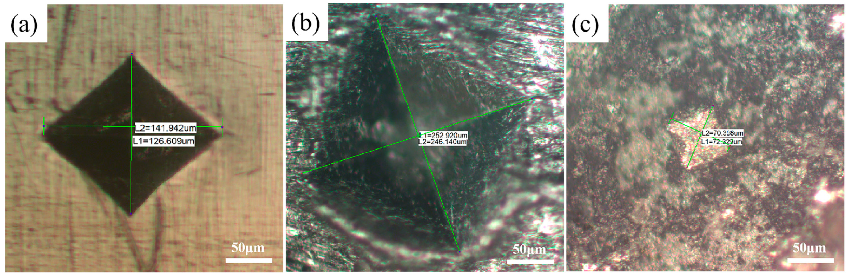
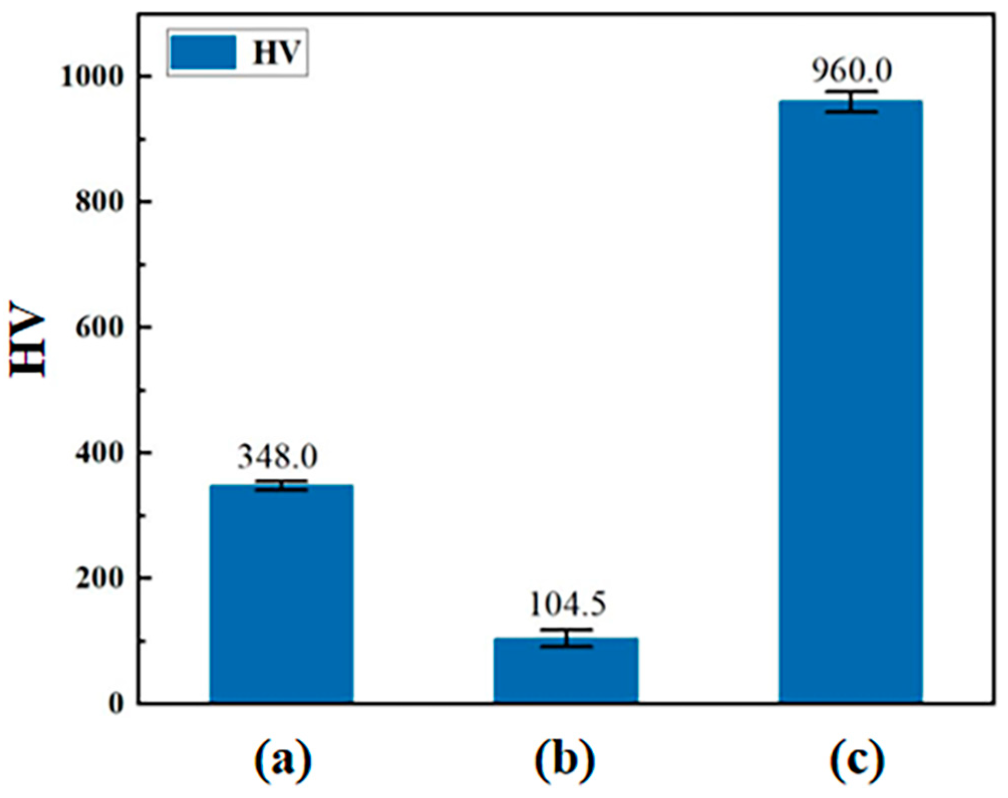
Figure 11 and Figure 12 show the indentation patterns and surface hardness values of the uncoated Ti65 sample, the hot-dip-aluminized (760 °C × 10 min) Ti65 sample, and the hot-dip-aluminized (760 °C × 10 min) and carburized (1050 °C × 4 h) Ti65 sample, respectively. From Figure 12, we find that the surface hardness of the composite coating is better than that of the titanium alloy substrate, and the problem of the sharp decline of the hardness of the single aluminized coating is avoided. In general, the greater the hardness of the material, the better its wear resistance, and the smaller its coefficient of friction. The reason why the hardness of the Ti65 sample increased significantly after hot-dip aluminizing (760 °C × 10 min) and carburizing (1050 °C × 4 h) is that the carbide particles formed in the Ti-Al carburizing layer played a strengthening role.
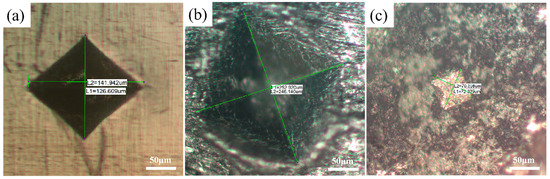
Figure 11.
The indentation patterns of (a) the uncoated Ti65 sample, (b) the hot-dip-aluminized (760 °C × 10 min) Ti65 sample, (c) the hot-dip-aluminized (760 °C × 10 min) and carburized (1050 °C × 4 h) Ti65 sample.

Figure 12.
Surface hardness values measured with a force of 3 Kg of (a) the uncoated Ti65 sample, (b) the hot-dip-aluminized (760 °C × 10 min) Ti65 sample, (c) the hot-dip-aluminized (760 °C × 10 min) and carburized (1050 °C × 4 h) Ti65 sample.
4. Conclusions
In this study, a Ti–Al alloy phase layer/Ti–Al carburizing composite coating was formed on the surface of titanium alloy by the stepwise coating method of hot-dip aluminizing and then carburizing. The microstructure, formation mechanism, and growth kinetics of the composite coating were systematically studied. At 800 °C, the oxidation behavior of the uncoated Ti65 sample, the hot-dip-aluminized (760 °C × 10 min) Ti65 sample, and the hot-dip-aluminized (760 °C × 10 min) and carburized (1050 °C × 4 h) Ti65 sample over 2–16 days was observed and analyzed. The conclusion is as follows:
- (1)
- During hot-dip aluminizing of the Ti65 sample, solid-liquid diffusion of Al and Ti atoms occurs on the surface of titanium alloy to form a TiAl3 phase +L-(Ti,Al) mixed-phase layer and a L-(Ti,Al) layer. After carburizing, the surface L-(Ti,Al) layer reacts with active carbon atoms to form a Ti–Al carburizing layer. The aluminum element in the TiAl3 phase layer continues to diffuse to the substrate, and the titanium element in the substrate continues to diffuse to the coating. Al and Ti continue to react to form a series of Ti–Al alloy phase layers (TiAl2, TiAl, Ti3Al) from outside to inside. Finally, the Ti–Al alloy phase layer/Ti–Al carburizing layer composite coating is formed.
- (2)
- After 800 °C × 16 days of thermal exposure testing, the oxidation kinetics curves of the three groups of samples all conform to the parabola law. In addition, the oxidation gain of the uncoated Ti65 is about 50 times that of the hot-dip-aluminized and carburized Ti65, and the oxidation gain of the hot-dip-aluminized Ti65 is about 2.6 times that of the hot-dip-aluminized and carburized Ti65. Therefore, the composite coating has excellent oxidation resistance at high temperatures.
- (3)
- During the oxidation process, TiAl3 is consumed by oxidation, but the loss of TiAl3 has no obvious effect on the oxidation rate. This is because the mixed-phase layer of TiAl2 and Al2O3 formed during the oxidation process is relatively continuous and dense and has good oxidation resistance at high temperatures, which can effectively prevent the further diffusion of oxygen elements to the substrate. This indicates that the Ti65 samples coated with the composite coating have long-term stability in 800 °C air (≥16 days).
- (4)
- The surface hardness of the composite coating is better than that of the titanium alloy substrate, and the problem of the sharp decline of the hardness of the single aluminized coating is avoided.
Author Contributions
Investigation, data curation, writing—original draft, W.Y.; project administration, methodology, writing—review and editing, F.L. All authors have read and agreed to the published version of the manuscript.
Funding
This research was funded by the Science and Technology Project of Education Department of Hunan Province (No. 22A0100), Hunan Provincial Natural Science Foundation of China (No. 2021JJ30672), and “National Innovation and Entrepreneurship Training Program for College Students” project (No. 202210530036).
Institutional Review Board Statement
Not applicable.
Informed Consent Statement
Not applicable.
Data Availability Statement
Not applicable.
Acknowledgments
The authors gratefully acknowledge the support provided by Materials Intelligent Design College Students’ Innovation and Entrepreneurship Education Center, Xiangtan University, Xiangtan, Hunan, China.
Conflicts of Interest
The authors declare no conflict of interest.
References
- Dai, J.; Li, S.; Zhang, H.; Yu, H.; Chen, C.; Li, Y. Microstructure and high-temperature oxidation resistance of Ti-Al-Nb coatings on a Ti-6Al-4V alloy fabricated by laser surface alloying. Surf. Coat. Technol. 2018, 344, 479–488. [Google Scholar] [CrossRef]
- Huang, L.; An, Q.; Geng, L.; Wang, S.; Jiang, S.; Cui, X.; Zhang, R.; Sun, F.; Jiao, Y.; Chen, X.; et al. Multiscale Architecture and Superior High-Temperature Performance of Discontinuously Reinforced Titanium Matrix Composites. Adv. Mater. 2021, 33, 2000688. [Google Scholar] [CrossRef]
- Li, B.; Zhou, H.; Liu, J.; Kang, C. Multiaxial fatigue damage and reliability assessment of aero-engine compressor blades made of TC4 titanium alloy. Aerosp. Sci. Technol. 2021, 119, 107107. [Google Scholar] [CrossRef]
- Zhang, X.; Chen, Y.; Hu, J. Recent advances in the development of aerospace materials. Prog. Aerosp. Sci. 2018, 97, 22–34. [Google Scholar] [CrossRef]
- Dai, J.; Zhu, J.; Chen, C.; Weng, F. High temperature oxidation behavior and research status of modifications on improving high temperature oxidation resistance of titanium alloys and titanium aluminides: A review. J. Alloys Compd. 2016, 685, 784–798. [Google Scholar] [CrossRef]
- Yuan, S.; Lin, N.; Zou, J.; Lin, X.; Liu, Z.; Yu, Y.; Wang, Z.; Zeng, Q.; Chen, W.; Tian, L.; et al. In-situ fabrication of gradient titanium oxide ceramic coating on laser surface textured Ti6Al4V alloy with improved mechanical property and wear performance. Vacuum 2020, 176, 109327. [Google Scholar] [CrossRef]
- Wang, D.Q.; Shi, Z.Y.; Teng, Y.L. Microstructure and oxidation of hot-dip aluminized titanium at high temperature. Appl. Surf. Sci. 2005, 250, 238–246. [Google Scholar] [CrossRef]
- Zhang, Z.G.; Peng, Y.P.; Mao, Y.L.; Pang, C.J.; Lu, L.Y. Effect of hot-dip aluminizing on the oxidation resistance of Ti-6Al-4V alloy at high temperatures. Corros. Sci. 2012, 55, 187–193. [Google Scholar] [CrossRef]
- Li, Z.W.; Gao, W.; Ying, D.Y.; Zhang, D.L. Improved oxidation resistance of Ti with a thermal sprayed Ti3Al(O)-Al2O3 composite coating. Scr. Mater. 2003, 48, 1649–1653. [Google Scholar] [CrossRef]
- Zhou, Z.; Xie, F.; Hu, J. A novel powder aluminizing technology assisted by direct current field at low temperatures. Surf. Coat. Technol. 2008, 203, 23–27. [Google Scholar] [CrossRef]
- Chen, Y.; Newkirk, J.W.; Liou, F. Synthesizing Ti-Ni Alloy Composite Coating on Ti-6Al-4V Surface from Laser Surface Modification. Metals 2023, 13, 243. [Google Scholar] [CrossRef]
- Zhang, X.J.; Gao, Y.H.; Ren, B.Y.; Tsubaki, N. Improvement of high-temperature oxidation resistance of titanium-based alloy by sol-gel method. J. Mater. Sci. 2010, 45, 1622–1628. [Google Scholar] [CrossRef]
- Hu, X.; Li, F.; Shi, D.; Xie, Y.; Li, Z.; Yin, F. A design of self-generated Ti-Al-Si gradient coatings on Ti-6Al-4V alloy based on silicon concentration gradient. J. Alloys Compd. 2020, 830, 154670. [Google Scholar] [CrossRef]
- Wang, Z.; Li, F.; Hu, X.; He, W.; Liu, Z.; Tan, Y. Preparation of Ti-Al-Si Gradient Coating Based on Silicon Concentration Gradient and Added-Ce. Coatings 2022, 12, 683. [Google Scholar] [CrossRef]
- Wang, C.J.; Lee, J.W.; Twu, T.H. Corrosion behaviors of low carbon steel, SUS310 and Fe-Mn-Al alloy with hot-dipped aluminum coatings in NaCl-induced hot corrosion. Surf. Coat. Technol. 2003, 163, 37–43. [Google Scholar] [CrossRef]
- Han, S.; Li, H.; Wang, S.; Jiang, L.; Liu, X. Influence of silicon on hot-dip aluminizing process and subsequent oxidation for preparing hydrogen/tritium permeation barrier. Int. J. Hydrogen Energ 2010, 35, 2689–2693. [Google Scholar] [CrossRef]
- Ren, X.; Wang, F. High-temperature oxidation and hot-corrosion behavior of a sputtered NiCrAlY coating with and without aluminizing. Surf. Coat. Technol. 2006, 201, 30–37. [Google Scholar] [CrossRef]
- Khanna, R.; Kokubo, T.; Matsushita, T.; Nomura, Y.; Nose, N.; Oomori, Y.; Yoshida, T.; Wakita, K.; Takadama, H. Novel artificial hip joint: A layer of alumina on Ti-6Al-4V alloy formed by Micro-arc oxidation. Mater. Sci. Eng. C-Mater. Biol. Appl. 2015, 55, 393–400. [Google Scholar] [CrossRef]
- Parekh, T.; Patel, P.; Sasmal, C.S.; Jamnapara, N.I. Effect of plasma processed Ti-Al coating on oxidation and tensile behavior of Ti6Al4V alloy. Surf. Coat. Technol. 2020, 394, 125704. [Google Scholar] [CrossRef]
- Duan, H.-q.; Han, Y.-f.; LÜ, W.-j.; Mao, J.-w.; Wang, L.-q.; Zhang, D. Effect of solid carburization on surface microstructure and hardness of Ti-6Al-4V alloy and (TiB + La2O3)/Ti-6Al-4V composite. Trans. Nonferrous Met. Soc. China 2016, 26, 1871–1877. [Google Scholar] [CrossRef]
- Bai, H.; Zhong, L.; Kang, L.; Liu, J.; Zhuang, W.; Lv, Z.; Xu, Y. A review on wear-resistant coating with high hardness and high toughness on the surface of titanium alloy. J. Alloys Compd. 2021, 882, 160645. [Google Scholar] [CrossRef]
- Liu, J.-P.; Luo, L.-S.; Su, Y.-Q.; Xu, Y.-J.; Li, X.-Z.; Chen, R.-R.; Guo, J.-J.; Fu, H.-Z. Numerical simulation of intermediate phase growth in Ti/Al alternate foils. Trans. Nonferrous Met. Soc. China 2011, 21, 598–603. [Google Scholar] [CrossRef]
- Goda, D.J.; Richards, N.L.; Caley, W.F.; Chaturvedi, M.C. The effect of processing variables on the structure and chemistry of Ti-aluminide based LMCS. Mater. Sci. Eng. A-Struct. Mater. Prop. Microstruct. Process. 2002, 334, 280–290. [Google Scholar] [CrossRef]
- Martin, R.; Kampe, S.L.; Marte, J.S.; Pete, T.P. Microstructure/processing relationships in reaction-synthesized titanium aluminide intermetallic matrix composites. Metall. Mater. Trans. A-Phys. Metall. Mater. Sci. 2002, 33, 2747–2753. [Google Scholar] [CrossRef]
- Fu, E.K.Y.; Rawlings, R.D.; McShane, H.B. Reaction synthesis of titanium aluminides. J. Mater. Sci. 2001, 36, 5537–5542. [Google Scholar] [CrossRef]
- Kong, L.; Qi, J.; Lu, B.; Yang, R.; Cui, X.; Li, T.; Xiong, T. Oxidation resistance of TiAl3-Al composite coating on orthorhombic Ti2AlNb based alloy. Surf. Coat. Technol. 2010, 204, 2262–2267. [Google Scholar] [CrossRef]
- Zhao, Y.G.; Zhou, W.; Qin, Q.D.; Liang, Y.H.; Jiang, Q.C. Effect of pre-oxidation on the properties of aluminide coating layers formed on Ti alloys. J. Alloys Compd. 2005, 391, 136–140. [Google Scholar] [CrossRef]
- Marder, A.R. The metallurgy of zinc-coated steel. Prog. Mater. Sci. 2000, 45, 191–271. [Google Scholar] [CrossRef]
- Yang, W.; Park, J.; Choi, K.; Chung, C.H.; Lee, J.; Zhu, J.; Zhang, F.; Park, J.S. Evaluation of growth kinetics of aluminide coating layers on Ti-6Al-4V alloys by pack cementation and the oxidation behaviours of the coated Ti-6Al-4V alloys. Int. J. Refract. Met. Hard Mater. 2021, 101, 105642. [Google Scholar] [CrossRef]
- Zhang, K.; Wang, Q.M.; Sun, C.; Wang, F.H. Preparation and oxidation resistance of a crack-free Al diffusion coating on Ti22Al26Nb. Corros. Sci. 2007, 49, 3598–3609. [Google Scholar] [CrossRef]
- Ebach-Stahl, A.; Eilers, C.; Laska, N.; Braun, R. Cyclic oxidation behaviour of the titanium alloys Ti-6242 and Ti-17 with Ti–Al–Cr–Y coatings at 600 and 700 °C in air. Surf. Coat. Technol. 2013, 223, 24–31. [Google Scholar] [CrossRef]
- Zhao, P.; Li, J.; Zhang, Y.; Li, X.; Xia, M.M.; Yuan, B.G. Wear and high-temperature oxidation resistances of AlNbTaZrx high-entropy alloys coatings fabricated on Ti6Al4V by laser cladding. J. Alloys Compd. 2021, 862, 158405. [Google Scholar] [CrossRef]
- Chen, L.; Zhang, X.; Wu, Y.; Chen, C.; Li, Y.; Zhou, W.; Ren, X. Effect of surface morphology and microstructure on the hot corrosion behavior of TiC/IN625 coatings prepared by extreme high-speed laser cladding. Corros. Sci. 2022, 201, 110271. [Google Scholar] [CrossRef]
- Haftani, M.; Saeedi Heydari, M.; Baharvandi, H.R.; Ehsani, N. Studying the oxidation of Ti2AlC MAX phase in atmosphere: A review. Int. J. Refract. Met. Hard Mater. 2016, 61, 51–60. [Google Scholar] [CrossRef]
- Lihrmann, J.M. Thermodynamics of the Al2O3–Al4C3 system. J. Eur. Ceram. Soc. 2008, 28, 633–642. [Google Scholar] [CrossRef]
- Li, J.; Shao, H.; Liu, T.; Zhang, K.; Yan, Z.; Liao, W. Preparation of Ti2AlC through in-situ selective laser forming and reaction sintering. Ceram. Int. 2021, 47, 22356–22364. [Google Scholar] [CrossRef]
- Jiao, X.; Cai, X.; Niu, G.; Ren, X.; Kang, X.; Feng, P. Rapid reactive synthesis of TiAl3 intermetallics by thermal explosion and its oxidation resistance at high temperature. Prog. Nat. Sci. Mater. Int. 2019, 29, 447–452. [Google Scholar] [CrossRef]
Disclaimer/Publisher’s Note: The statements, opinions and data contained in all publications are solely those of the individual author(s) and contributor(s) and not of MDPI and/or the editor(s). MDPI and/or the editor(s) disclaim responsibility for any injury to people or property resulting from any ideas, methods, instructions or products referred to in the content. |
© 2023 by the authors. Licensee MDPI, Basel, Switzerland. This article is an open access article distributed under the terms and conditions of the Creative Commons Attribution (CC BY) license (https://creativecommons.org/licenses/by/4.0/).