Abstract
In the present study, the ablation of a pintle injector on a 500N GOX/GCH4 rocket engine under different working conditions is studied experimentally and numerically. The temperature of the pintle tip and the combustion gas in the head zone was measured in a series of experiments by the thermocouples. Moreover, a three-dimensional model was established to simulate combustion and heat transfer concurrently and analyze the ablation state of the pintle injectors. The obtained results indicate that under a low chamber pressure () and an increasing O/F ratio from 0.8 to 2, the tip temperature declines first, and then rises. At the designed working condition (and O/F = 3.2), the pintle tip suffered serious ablation, and the microstructure analysis indicates that the ablation failure of the stainless steel pintle tip originates from chromium precipitation. This phenomenon is especially more pronounced when the temperature exceeds 1273 K, which makes the structure fragile and vulnerable. This article helps to provide an understanding of the ablation failure of the pintle injectors, and the established model is capable of giving a prediction on the ablation status of the pintle tips consistent with the experiment.
1. Introduction
Since the development of the pintle injector in the jet propulsion laboratory (JPL) in the 1950s [1], it has been used in the lunar module descent engine (LMDE) in the Apollo project at the end of the 1960s [2] and in the development of the Merlin series engines of the SpaceX corporation in the late 2010s [3]. Numerous tests under various conditions demonstrate that pintle engines with a simple structure and low manufacturing cost have superior characteristics such as stable combustion, high-performance deep throttling, and excellent adaptability and reliability in the variable thrust occasions such as rocket recycling and planet landing operations.
However, the imperfection of the pintle injector is also noteworthy. Generally, there are two pairs of recirculation zones in the thrust chamber of a pintle engine as shown in Figure 1, which enhance mixing, increase the residence time of the propellants, and keep the combustion process stable. However, continuous combustion gas with a high temperature recirculates to the pintle tip, heating the tip and even overheating it. This phenomenon is one of the main drawbacks of pintle injectors [4]. Therefore, Betts thought it is necessary to calculate the allowable temperature of pintle injectors and optimize the tip material to avoid overheating [5]. Particularly, Heister held that pintle engines require a higher degree of integrated design of the pintle injector and the combustion chamber than other types of rocket engines [6].
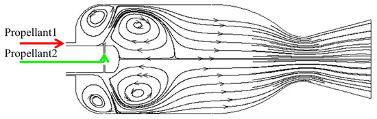
Figure 1.
Streamline inside the thrust chamber of pintle engines.
Currently, most investigations are devoted to the atomization characteristics [7,8,9,10,11,12,13] and combustion performance of pintle injectors [14,15,16,17,18], so further investigations are required on the thermal protection and ablation-induced problems. Especially for cryogenic bipropellants such as liquid oxygen (LOX)/liquid hydrogen (LH2) and LOX/liquid methane (LCH4), the pintle tip ablation cannot be ignored. Bedard found that although an active cooling system was adopted to protect the tip, the pintle tip obviously ablated in the hot tests of a LOX/LCH4 pintle engine [19]. The active cooling design for the pintle engines was first proposed by Thomas J. Mueller [20], the designer of the Merlin series engines which use LOX/kerosene as propellants and report no ablation failure of the pintle injectors. It indicates that the pintle ablation is notably influenced by the types and states of the propellants used. To solve the ablation problem of the pintle injectors, Gromski analyzed heat transfer in the TR202 LOX/LH2 pintle engine to explore the effects of different geometries and thrust throttling levels on the heat flux of the pintle injector [21]; however, detailed results are not disclosed in public references. Kang discovered that changing the shape of the pintle orifice and setting an insert nozzle inside the pintle body can significantly improve the pintle tip cooling performance [22], but this method limits further optimization of the whole pintle engine performance.
The performed literature survey reflects that there is a lack of systematic and specialized studies on the ablation problem of pintle injectors [23]. Aimed at resolving this shortcoming, the ablation status of a pintle injector under different working conditions was studied experimentally. To this end, the tests were conducted on a gas oxygen (GOX)/gas methane (GCH4) pintle engine. Moreover, a numerical model was developed to study the heat transfer and combustion within the thrust chamber, predict the temperature on the pintle tip, and obtain flow field information around the pintle injector. As an innovative work, the achievements of this article can instruct the design of the pintle engines and provide a further interpretation on the ablation failure of the pintle injectors.
2. Experimental Facilities
2.1. Pintle Engine
In this article, a 500 N vacuum thrust-class pintle engine with a nominal chamber pressure of 1.05 MPa was used to conduct the tests. Figure 2 shows a schematic view of the pintle engine equipped with thermocouples. In this engine, GCH4 flows inside the pintle body and radially injects from double rows of circular injection holes, while GOX axially flows along the outer pintle wall from the annular gap. To increase the resistance of the thrust chamber to high temperatures, the dome head plate is protected by a composite layer made from ethylene–propylene–diene monomer (EPDM) and carbon fiber, while the rest of the thrust chamber is water-cooled. Except for the copper thrust chamber, the other parts of the engine are made of 304 stainless steel. Figure 3 shows the physical engine and its main parts.
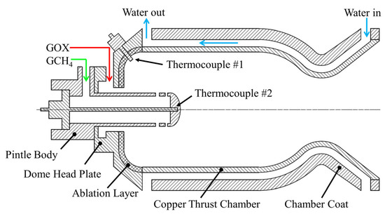
Figure 2.
Schematic diagram of the pintle engine equipped with thermocouples.
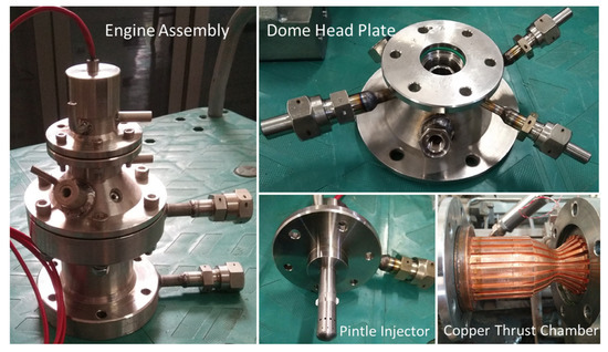
Figure 3.
Configuration of the pintle engine.
To measure the temperature of the pintle tip and combustion gases, two tungsten–rhenium thermocouples with a maximum operating temperature of 2300 °C were embedded inside the pintle injector and dome head plate. The temperature measured by the thermocouple #1 welded at the pintle tip is actually the solid domain temperature because the thermocouple probe at this location is covered by pintle injector material to protect it from the hot oxidizing atmosphere. Figure 2 shows that the other thermocouple #2 mounted on the dome head plate is in direct contact with combustion gas. These two temperatures reflect the thermal state of the pintle injector.
To simplify the test preparation and ignition, GOX/GCH4 at room temperature is used in tests. At the design point, the O/F and total mass flow rate were 3.2 and 152 g/s, respectively. The ignition is accomplished via an electric spark plug mounted on the dome head plate. The main parameters related to the performance and geometry structures of the engine are listed in Table 1.

Table 1.
Parameters of a 500N GOX/GCH4 pintle engine.
2.2. Test Stand and Instrumentation
In this article, all tests were conducted on the test stand of the combustion mechanism of liquid rocket engines at the Science and Technology on Scramjet Laboratory of National University of Defense Technology, China. Figure 4 shows the configuration of the test setup. The control/measurement system consists of a PXI collection system and a PLC controller to adjust the pneumatic valves and collect the data concurrently according to the given time sequence. During the tests, the pressure, temperature, and flow rate were measured and recorded on a data card. The pressure was measured using piezoresistive pressure transmitters with a response frequency of 20 kHz and a measuring precision of 0.5% full scale (FS). Moreover, the temperature was measured using thermocouples mentioned above with a precision of 1%FS. Finally, the volumetric flow rate was measured using turbine meters with a precision of 1%FS.
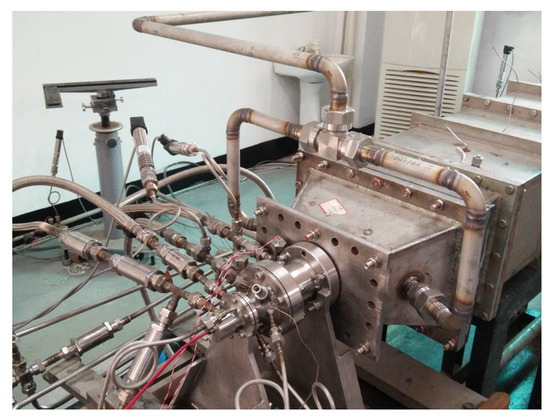
Figure 4.
Configuration of the test system on the LRE test stand.
The specific working conditions are listed in Table 2, where is the maximum theoretical temperature of the thrust chamber in each condition.
Table 2.
Definitions of working conditions.
3. Numerical Methodology
3.1. Model Simplification
The main objective of the numerical simulation is to analyze the combustion inside the thrust chamber and calculate the heat transfer between the hot gas and the pintle injector. In order to reduce the computational expenses, a simplified model is developed, as shown in Figure 5, and the geometric parameters are set according to the physical engine. Because the thrust chamber is axially symmetrical and the pintle injector has double rows of circumferential holes in a stagger arrangement, with each row having 12 holes as shown in Figure 6, only 1/24 of the engine model is simulated as the computational domain.
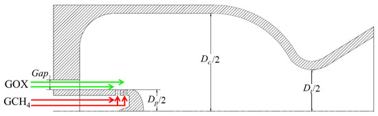
Figure 5.
Simplified model of the study’s pintle engine.
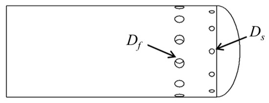
Figure 6.
Arrangement of circular injection holes on the pintle injector.
When designing a pintle injector, two dimensionless quantities, and , are defined to describe the dynamics of the propellants. denotes the blockage factor and reflects the proportion of intersecting and mixing of the fuel and oxidizer. For the present pintle, BF can be expressed as follows:
is the total momentum ratio and reflects the impact intensity of the fuel jets and oxygen film flow, which can be mathematically expressed in the following form:
Therefore, the circumferential length and injection area of the injection holes can be adjusted using and , respectively.
3.2. Governing Equations
In the present study, the physical process consists of the gas turbulent flow, combustion, and heat transfer between the gas and the pintle injector. First, the standard k-ε turbulent model is satisfactory on the simulation of the combustion gas flow according to the previous work [24], so it is selected to describe the steady-state gas flow. In addition, all of the gases can be approximately assumed to be the ideal gas. Second, a reduced Jones–Lindstedt six-step mechanism (JL6) [25] is employed to model the chemical reactions of methane and oxygen, which contains six equations and nine species. JL6 shows an acceptable calculation precision and an affordable computation cost in similar research [15,26]. Third, to calculate the convective heat transfer between the fluid and solid walls, a method is applied by enforcing the continuity of the temperature and heat flux to sustain a thermal balance. This can be mathematically expressed as follows:
In addition, the thermal conduction in the solid domain of the pintle body can be calculated using the Fourier equation, in which the thermal conductivity of the solid domain of stainless steel is set to 18.3 W/(m•K). Detailed equations are seen in the previous work [22].
3.3. Numerical Method
The second-order upwind scheme is used for the spatial discretization of the governing equations, and the SIMPLE algorithm is adopted to solve the coupled pressure–velocity equations.
3.4. Grid Generation and Boundary Conditions
Figure 7 shows a three-dimensional structured grid of the engine model. The grid consists of the fluid domain and the solid domain, which were generated separately. The nodes at the solid–fluid interface are non-conformal due to the geometry complexity. Therefore, heat exchange at the interface is achieved via interpolation. To improve the solution accuracy at the solid–fluid interface, the boundary layer is established in both the fluid and solid domain in the vicinity of the interface. GOX and methane inlets were considered mass flow rate inlets, while the outlet was considered a pressure outlet. Only the interface walls that stand between the solid and fluid domains are coupled walls, namely, the walls considered with heat transfer, while the other walls are adiabatic. Furthermore, all walls are assumed to have a non-slip surface. The imposed boundary conditions at the design point are summarized in Table 3.
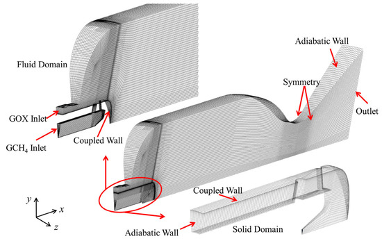
Figure 7.
Generated grids in the computational domain.
Table 3.
The imposed boundary conditions.
3.5. Grid Independence Tests
Three grid resolutions with different grid densities were compared in grid independence tests. The coarse, moderate, and fine grids contain 107,484, 226,290, and 487,080 hexahedron cells in the fluid domain, respectively, while the grid densities in the solid domain stay constant. In order to observe the effects of grid densities, a sample line shown in Figure 8 was selected and Figure 9 presents the temperature distributions along the X-direction on the sample line. The obtained results show that the moderate grid agrees well with the fine grid. The maximum temperature on the sample line is 1573 K for the moderate grid, which is 4.83% lower than the maximum temperature of 1649 K for the fine grid. Therefore, to balance the computational costs and precision of the numerical results, the moderate grid is adopted in all simulations. Symmetry planes A and B are used to analyze the flow field in the next section.
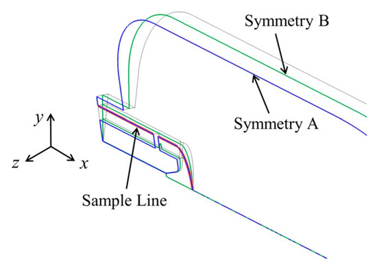
Figure 8.
Sample line and symmetries for the analysis.
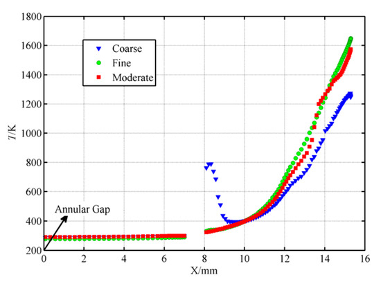
Figure 9.
Temperature distributions on the sample line with different grid densities.
4. Results and Discussions
To obtain reliable measuring results, the experiments under conditions #1-#6 were carried out for 1 to 5 s. The thrust chamber pressure , methane/oxygen pressure before injection and were recorded. Figure 10 shows the distribution of , , and against time in test #6, indicating that these pressure data are much more stable with very small fluctuations in the firing time. Actually, combustion stability is one of the typical characteristics and inherent advantages of the pintle engines.
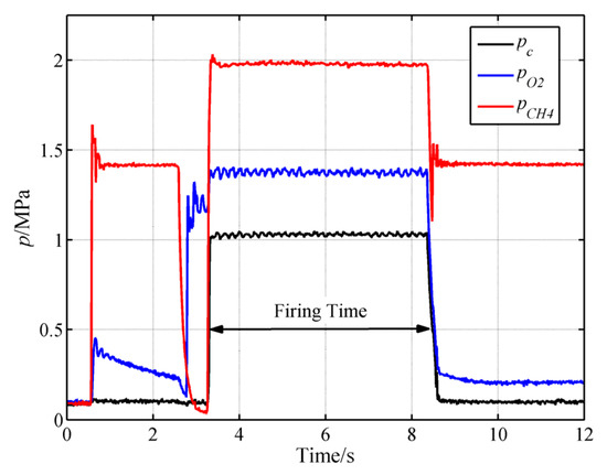
Figure 10.
Distribution of , , and against time in test #6.
Figure 11 and Figure 12 illustrate the distribution of the combustion gas temperature measured by thermocouple #1, and the pintle tip temperature measured by thermocouple #2 against time, respectively. In test #5, it takes up to 3 s to reach a stable and 5 s to reach a stable . The same situations occur in tests #1~#4. Therefore, the temperatures after 5 s are used as stable values, noting that Time 0s means the moment of ignition in Figure 11, Figure 12, Figure 13 and Figure 14.
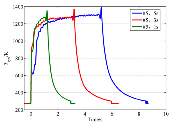
Figure 11.
Distribution of against time in test #5.
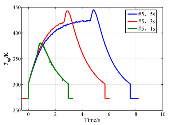
Figure 12.
Distribution of against time in test #5.
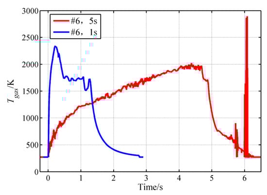
Figure 13.
Distribution of against time in test #6.
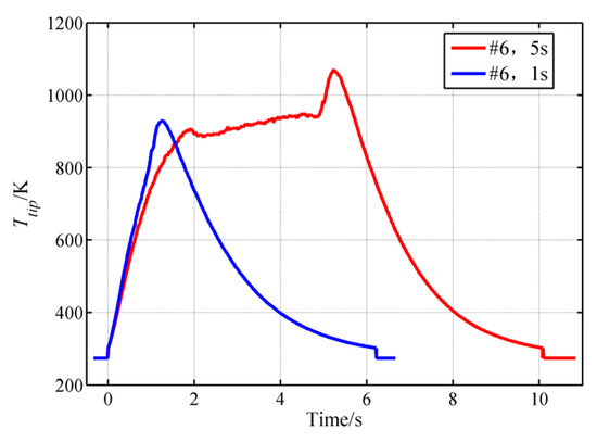
Figure 14.
Distribution of against time in test #6.
Figure 13 and Figure 14 show that in test #6, neither nor reaches a steady-state condition even after 5 s. In this test case, the final and are 930.14 K and 1950.6 K, respectively. Additionally, it is noteworthy that all 24 firing tests up to 65 seconds were conducted with the same engine and thermocouples. Finally, it was discovered that the pintle tip was severely overheated in test #6. Therefore, the temperature data collected in test #6 cannot reflect the practical situation. A comprehensive analysis and explanation are discussed in Section 4.3.
4.1. Effects of O/F on the Thermal Environment of the Pintle Injector
Tests #1 to #4 are performed under a of 0.25 MPa, but an O/F ratio of 0.8, 1.2, 1.6, and 2, successively. Figure 15 shows that the experimental and numerical results are consistent on the distribution of for different O/F ratios.
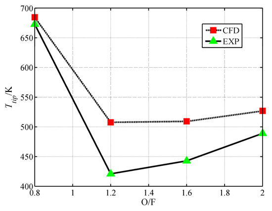
Figure 15.
for different O/F ratios.
Both the experimental and numerical results indicate that declines first, and then rises with an increasing O/F ratio. The quantitative analysis in Table 4 further manifests that as the O/F ratio increases, the corresponding likewise declines first and then rises. The maximum and minimum ratio of are 20.59% and 1.75%, respectively, which proves that the established model is capable of giving a prediction on the ablation status of the pintle tips consistent with the reality. Here, is defined in the following form:
Table 4.
Deviations between numerical and experimental results for test cases #1~#4.
In tests #1 to #4 with the same chamber pressure, the O/F ratio increases as the oxygen mass flow rate increases, and the methane mass flow rate decreases. As a result, reduces, meaning that the momentum of the axial oxygen film rises while the momentum of the radial methane jets declines. Figure 16 shows that the vertically injecting methane jet gradually inclines downstream, which is mainly attributed to the impact influence of the oxygen film flow on the methane jet.
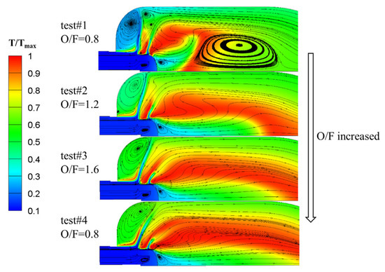
Figure 16.
Comparison of flow fields in the symmetry plane B in tests #1 to #4.
Meanwhile, Figure 17 shows that as the O/F ratio increases, the vertical dimension of the methane jets also reduces significantly, which is represented by the iso-surface of methane gas with a mass fraction of 0.6. Obviously, methane jets are pushed downstream with an increasing O/F ratio. This phenomenon improves mixing and combustion in the head zone and central zone of the thrust chamber. Logically speaking, more sufficient combustion and heat release will increase the pintle tip temperature; however, this is not observed in experimental or numerical results. There are two reasons to explain this paradox. Firstly, as the O/F ratio increases, Figure 16 reveals that there was no recirculation zone formed in the center of the thrust chamber in tests #2 to #4; therefore, high-temperature combustion gas does not return and does not heat the pintle tip. Secondly, it is observed in Figure 16 and Figure 17 that as the O/F ratio increases, considerable oxygen flows into the small recirculation zone under the pintle tip, thereby creating an oxygen-rich environment that further protects the pintle tip.
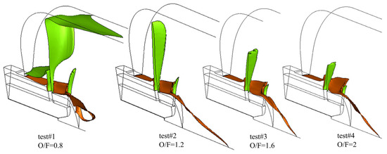
Figure 17.
Comparison of iso-surfaces in tests #1 to #4 (green: iso-surface of methane gas with a mass fraction of 0.6; puce: iso-surface of oxygen with a mass fraction of 0.9).
4.2. Effects of O/F Ratio and on the Thermal Environment of the Pintle Injector
Figure 18 shows a bubble graphic of the dependence of on the O/F ratio and . The bubble diameter reflects the relative magnitude of the corresponding temperature. Moreover, each pair of bubbles for the corresponding test is non-concentric because the are not identical.
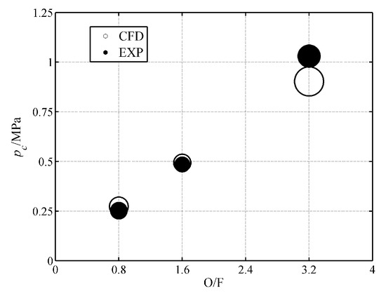
Figure 18.
Dependence of on O/F and .
Both the numerical and experimental results show that as the O/F ratio and increase concurrently, the corresponding declines and then rises. Secondly, Table 5 reveals that the numerical results basically agree with the experimental results for tests #1 and #5, but there is a large deviation between the two methods in test #6. Section 4.3 discusses this abnormal result.
Table 5.
Deviations between simulation and experiment results for tests #1, #5, and #6.
Table 2 indicates that in tests #1, #5, and #6, with similar methane mass flow rates, the O/F ratio and increase with the increasing oxygen mass flow rate. Among these test cases, the highest occurs in test #1, so this case has the lowest impact effect of the oxygen film flow on methane jets. Figure 19 shows that the oxygen film just bypasses the methane jets without sufficient mixing. Meanwhile, the methane jets with a larger momentum in test #1 not only impact the chamber wall, but also diffuse upstream of the injection holes. Consequently, the head zone temperature is much lower than the temperature in the other two tests. When the oxygen mass flow rate increases, the mixing of oxygen and methane strengthens, and the combustion in the whole chamber improves, thereby increasing the gas temperature in the head zone with the increasing O/F and . Figure 19 and Figure 20 illustrate the foregoing changes.
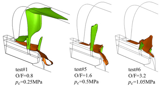
Figure 19.
Iso-surfaces in tests #1, #5, and #6 (green: iso-surface of methane with a mass fraction of 0.6; puce: iso-surface of oxygen with a mass fraction of 0.9).
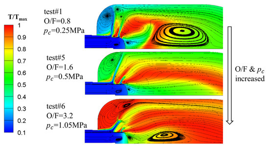
Figure 20.
The comparison of flow fields on the symmetry plane B for tests #1, #5, and #6.
The results presented in Section 4.1 and Section 4.2 demonstrate that among the studied cases, tests #2 to #5 do not have a large recirculation zone in the center of the chamber, and the corresponding is in the range from 500 K to 600 K. With the formation of the recirculation zone in tests #1 and #6, increases significantly, indicating that the appearance of the central recirculation zone remarkably affects the ablation status of the pintle tip. More specifically, when a central recirculation zone forms, the pintle tip is heated or even overheated by the high-temperature combustion gas. This phenomenon also explains the reason why declines and then rises in tests #1 to #6 as the O/F ratio and increase simultaneously.
4.3. Analysis on the Ablation Feature of the Pintle Injector
The in test #6 is just 930 K, while the ablation of the pintle tip after the test clearly indicates that the tip has approached the melting point of the pintle material during the test, which is generally in a range from 1671 to 1727 K and is far higher than 930 K. To explain this abnormal phenomenon, the structure of the ablation region is analyzed under a scanning electron microscope (SEM, Carl Zeiss AG, Jena, Germany) to obtain the true temperature of the pintle tip in test #6. Figure 21 shows a close-up view of the overheated pintle tip and its split along the symmetry plane for microscopic observation.
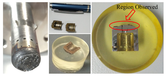
Figure 21.
Ablation feature of the pintle tip after test #6 and the sample for microscopic observation.
Firstly, Figure 22 reveals that the melted ablation occurred only after test #6. All tests were conducted according to a sequence from a low to high O/F and a short to long firing time until the pintle tip was burned severely after test #6. At a cumulative time of 6.05 s, the pintle tip turned brown, and an oxidized blue circle appeared at the edge of the pintle tip, which was then polished to avoid affecting the later observation. From a cumulative test time of 6.05 s to 32.35 s, which covers tests #1 to #5 with short firing times (1 s, 3 s), the pintle tip kept the brown feature and was insensitive to the work conditions. For a cumulative test time of 32.35 s to 57.35 s, which covers long experiments, the surface color on the pintle tip turned from brown to black, and the ablation deteriorated notably. After the last test #6, the pintle tip was totally destructed and there was no smooth surface anymore.
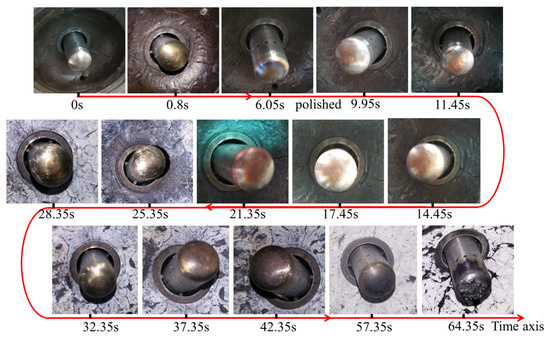
Figure 22.
Ablation change of the pintle tip with an increasing cumulative test time.
Secondly, Figure 23 shows microscopic features magnified 1000 times via a secondary electron (SE1). It is observed that there is an obvious stratification in the ablation region. The upper layer is the sedimentary deposit formed by the solidification of the melted stainless steel, where the top edge is rugged, and a nonuniform section with cavities forms. The lower layer is non-ablation stainless steel featuring a much more compact and homogeneous section. The structures of these two layers show a striking contrast in Figure 24 with a magnification of 200 times via backscattered electron (BSD). An analysis on the ablation failure of an aero-engine injector with a similar material [27] demonstrates that the loose and faveolate structure in the upper layer is the precipitated phase Cr23C6, and the element Cr originates from the austenite of the injector material.
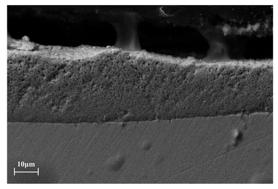
Figure 23.
Microscopic feature in the region (SE1, ×1000).
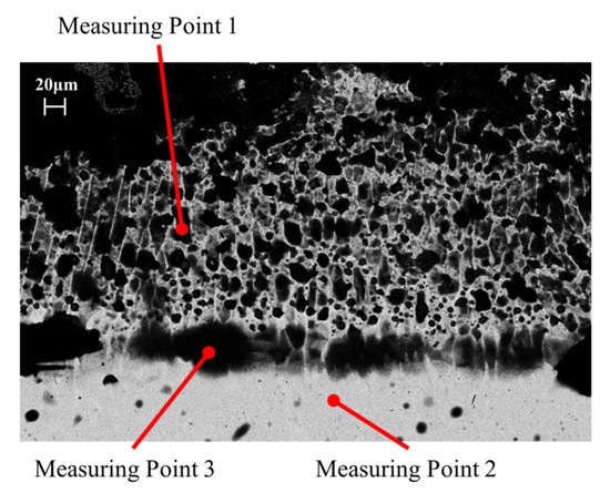
Figure 24.
Microscopic feature in the region (BSD, ×200).
By making an energy spectrum analysis at three measuring points, shown in Figure 24, the elementary composition at the corresponding point was achieved, in which the measuring points 1, 2, and 3 (MP1, MP2, and MP3) are located in the melting zone, stainless steel zone without ablation, and the interface of the two zones, respectively. The analysis result is listed in Table 6. First, the chemical composition of MP2 basically conforms to the standard GB/T 20878-2007 of the stainless steel material 06Cr19Ni10, indicating that MP2 is indeed located in the region without ablation. Second, in terms of the element Cr, MP2 < MP3 < MP1, which reflects the transporting path of Cr from the stainless steel zone to the melting zone. The energy spectrum analysis of the original images is shown in Figure 25.
Table 6.
Chemical compositions in measuring points.
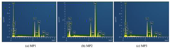
Figure 25.
Energy spectrum analysis of the MP1–MP3.
Generally, when the temperature is in a range from 723 to 1123 K, Cr23C6 dissolves at the boundaries of austenite grains, but when the temperature exceeds 1273 K, Cr23C6 decomposes. Under this condition, intergranular corrosion happens, which originates from Cr depletion and a lack of passivation ability of the steel. As a result, the material is extremely fragile and easily corroded. In a high-temperature and high-pressure thrust chamber, the fragile melting material smashes and forms the loose, faveolate structure. Therefore, it is inferred that the true temperature on the pintle tip in test #6 is close to the material melting point (1671~1727 K) or at least over 1273 K. Compared to the upper limit of 1727 K, the corresponding =1587.74 K is less than 8.1%, which indicates that the numerical results are more reliable than the experimental results of test #6.
Last but not least, it should be reminded that the whole experiment was conducted according to a time sequence, and neither the pintle injector nor the thermocouple were replaced, so the material of the pintle tip was actually not pure stainless steel before test #6. Consequently, such material degeneration may make the thermocouple provide the wrong results. Furthermore, the oxidation phenomenon of the tungsten–rhenium thermocouple [28] may be another latent reason why the temperature measured by the thermocouple is in contradiction with the ablation feature observed on the pintle tip in test #6. The loose and faveolate structure that appears in the pintle tip puts the thermocouple in an oxygen-rich environment with a high temperature and accelerates its oxidation and malfunction. A more comprehensive mechanism about this phenomenon needs further investigation in the future.
Except for the pintle tip that burned severely, Figure 25 shows that the region around the second row of injection holes oxidized and turned blue. Particularly, such oxidization with color change does not distribute uniformly along the circumferential direction. Considering the physical position of the thermocouple embedded in the dome head plate, this uneven distribution may be caused by its disturbance in the head zone. Figure 26 also shows a wavy shape at the edge of the oxidized region, and the wave crests correspond with the first row of injection holes, while the wave troughs correspond with the second row. The images with a magnification of 1000 times of the microstructures of the region with the wavy shape in Figure 27 show that continuous net structures appear in the vicinity of the side wall, which shares the same ablation mechanism as the pintle tip but behaves weaker than the tip position.
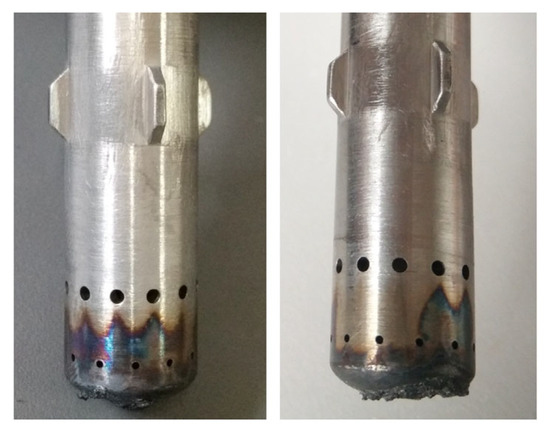
Figure 26.
Uneven distribution of oxidation and ablation feature around the injection holes.
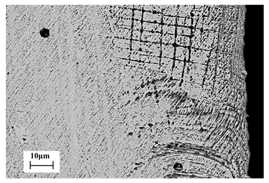
Figure 27.
Microscopic feature in the vicinity of the second row of injection holes (BSD, ×1000).
To sum up, the material of the pintle injector is easier to ablate at a high temperature and high pressure. In future works, we will use the ultra-high temperature ceramics prepared by Simonenko et al. as the protective coating to carry out follow-up research [29,30,31,32].
5. Conclusions
In this article, the ablation of the pintle injector in a 500N GOX/GCH4 rocket engine under different conditions is studied experimentally and numerically. Based on the performed analyses and obtained results, the main conclusions can be summarized as follows:
(1) The numerical simulations and experimental measurements obtained similar trends for the temperature of the pintle tip under different working conditions. As the O/F ratio and increase simultaneously, the pintle tip temperature declines first, and then rises. The formation of a large recirculation zone in the chamber center significantly increases the pintle tip temperature and affects the tip ablation status.
(2) Quantitative deviation between the numerical and experimental results on the pintle tip temperature is not satisfactory, but the present numerical model helps us preliminarily understand the flow and thermal environment of the pintle injector and why the injector experienced severe ablation. A better numerical model with high fidelity needs further development in the future.
(3) Due to the melting of the pintle injector material and the malfunction of the thermocouple embedded in the pintle tip, the pintle tip temperature measured at the design point is actually unreliable. The microstructure analysis indicates that the ablation failure of the stainless steel pintle tip originates from Chromium precipitation. This is especially pronounced when the temperature exceeds 1273 K, which generally makes the structure fragile and vulnerable. The present results manifest that the stainless steel material itself cannot resist high-temperature ablation for a GOX/GCH4 pintle engine, whereas the injection orifices shape optimization, and positive/negative cooling measures are required.
Author Contributions
Conceptualization, methodology, software, validation, investigation, and writing—original draft preparation, Y.C.; writing—review and editing, supervision, project administration, and funding acquisition, J.Z. All authors have read and agreed to the published version of the manuscript.
Funding
This research was funded by the National Natural Science Foundation of China (No. 11472303 and No. 11902351).
Institutional Review Board Statement
Not applicable.
Informed Consent Statement
Not applicable.
Data Availability Statement
Not applicable.
Acknowledgments
The authors would like to express their sincere thanks for administrative and technical support from Qinglian Li from Science and Technology on Scramjet Laboratory, National University of Defense Technology. Especially, thanks Qiong Zhan from Institute of Space Chemical Technology and the assistance of laboratory staff for the free supply of the ablation material in the experiment preparation.
Conflicts of Interest
The authors declare no conflict of interest. The funders had no role in the design of the study; in the collection, analyses, or interpretation of data; in the writing of the manuscript; or in the decision to publish the results.
Nomenclature
| BF | blockage factor |
| D | diameter, mm |
| L | length, mm |
| mass flow rate, kg/s | |
| O/F | mixture ratio of oxidizer to fuel |
| p | pressure, Pa |
| T | temperature, K |
| TMR | total momentum ratio |
| μ | velocity vector, m/s |
| λ | thermal conductivity, W/(m•K) |
| Superscript | |
| CFD | numerical result |
| EXP | experimental result |
| th | theoretical value |
| Subscript | |
| a | axial direction |
| c | combustion chamber |
| e | exit of the thrust chamber |
| f | first row of pintle injection holes |
| fluid | fluid zone |
| gas | combustion gas in the thrust chamber |
| p | pintle injector |
| r | radial direction |
| s | second row of pintle injection holes |
| solid | solid zone |
| tip | pintle tip |
References
- Dressler, G.A.; Bauer, M.J. Trw Pintle Engine Heritage and Performance Characteristics. In Proceedings of the 36th Aiaa/Asme/Sae/Asee Joint Propulsion Conference and Exhibit: American Institute of Aeronautics and Astronautics, Las Vegas, NV, USA, 24–28 July 2000. [Google Scholar] [CrossRef]
- Dressler, G.A. Summary of Deep Throttling Rocket Engines with Emphasis on Apollo Lmde. In Proceedings of the 42nd Aiaa/Asme/Sae/Asee Joint Propulsion Conference & Exhibit: American Institute of Aeronautics and Astronautics, Sacramento, CA, USA, 9–12 July 2006. [Google Scholar] [CrossRef]
- Vozoff, M.; John, C. Spacex Products-Advancing the Use of Space. In Proceedings of the Ai-aa Space 2008 Conference & Exposition: American Institute of Aeronautics and Astronautics, San Diego, CA, USA, 9–11 September 2008. [Google Scholar] [CrossRef]
- Casiano, M.J.; James, R.H.; Vigor, Y. Liquid-Propellant Rocket Engine Throttling: A Comprehensive Review. J. Propuls. Power 2010, 26, 897–923. [Google Scholar] [CrossRef]
- Betts, E.; Robert, F. A Historical Systems Study of Liquid Rocket Engine Throttling Capabilities. In Proceedings of the 46th Aiaa/Asme/Sae/Asee Joint Propulsion Conference & Exhibit: American Institute of Aeronautics and Astronautics, Nashville, TN, USA, 25–28 July 2010. [Google Scholar] [CrossRef]
- Heister, S.D. Pintle Injectors. In Handbook of Atomization and Sprays: Theory and Applications; Ashgriz, N., Ed.; Springer: Boston, MA, USA, 2011; pp. 647–655. [Google Scholar] [CrossRef]
- Fang, X.X.; Shen, C.B. Study on Atomization and Combustion Characteristics of Lox/Methane Pintle Injectors. Acta Astronaut. 2017, 136, 369–379. [Google Scholar] [CrossRef]
- Son, M.; Yu, K.; Koo, J.; Kwon, O.C.; Kim, J.S. Effects of Momentum Ratio and Weber Number on Spray Half Angles of Liquid Controlled Pintle I-njector. J. Therm. Sci. 2015, 24, 37–43. [Google Scholar] [CrossRef]
- Cheng, P.; Li, Q.L.; Chen, H.Y. Flow Characteristics of a Pintle Injector Element. Acta Astronaut. 2019, 154, 61–66. [Google Scholar] [CrossRef]
- Cheng, P.; Li, Q.L.; Xu, S.; Kang, Z.T. On the Prediction of Spray Angle of Liquid-Liquid Pintle Injectors. Acta Astronaut. 2017, 138, 145–151. [Google Scholar] [CrossRef]
- Radhakrishnan, K.; Lee, K.; Koo, J. A Detailed Modelling on Spray Atomisation and Combustion of Lox/Gch4 in Variable Area Pintle Injector Rocket Engines. Combust. Theory Model. 2021, 25, 718–750. [Google Scholar] [CrossRef]
- Jin, X.; Shen, C.; Lin, S.; Zhou, R. Experimental study on the spray characteristics of a gas–liquid pintle injector element. J. Vis. 2022, 25, 467–481. [Google Scholar] [CrossRef]
- Chen, H.; Li, Q.L.; Cheng, P. Experimental research on the spray characteristics of pintle injector. Acta Astronaut. 2019, 162, 424–435. [Google Scholar] [CrossRef]
- Zhou, R.; Shen, C.B. Influence of Momentum Ratio Control Mode on Spray and Combustion Characteristics of a Lox/Lch4 Pintle Injector. J. Zhejiang Univ.-SCIENCE A 2022, 23, 415–420. [Google Scholar] [CrossRef]
- Son, M.; Radhakrishnan, K.; Yoon, Y.; Koo, J. Numerical Study on the Combustion Characteristics of a Fuel-Centered Pintle Injector for Methane R-ocket Engines. Acta Astronaut. 2017, 135, 139–149. [Google Scholar] [CrossRef]
- Sakaki, K.; Kakudo, H.; Nakaya, S.; Tsue, M.; Kanai, R.; Suzuki, K.; Inagawa, T.; Hiraiwa, T. Performance Evaluation of Rocket Engine Combustors Using Ethanol/Liquid Oxygen Pintle Injector. In Proceedings of the 52nd Aiaa/Sae/Asee Joint Propulsion Conference: American Institute of Aeronautics and Astronautics, Salt Lake City, UT, USA, 25–27 July 2016. [Google Scholar] [CrossRef]
- Jin, Y.S.; Xu, X.; Yang, Q.C.; Zhu, S.H. Numerical Investigation of Fla-me Appearance and Heat Flux and in a Deep-Throttling Variable Thrust Rocket Engine. Aerosp. Sci. Technol. 2019, 88, 457–467. [Google Scholar] [CrossRef]
- Shen, C.B.; Zhou, R. Experimental Study on the Combustion Characteristics of Lox/Lch4 Pintle Injectors. Fuel 2023, 339, 126909. [Google Scholar] [CrossRef]
- Bedard, M.; Feldman, T.; Rettenmaier, A.; Anderson, W. Student Design/Build/Test of a Throttleable Lox-Lch4 Thrust Chamber. In Proceedings of the 48th Aiaa/Asme/Sae/Asee Joint Propulsion Conference & Exhibit: American Institute of Aeronautics and Astronautics, Atlanta, GA, USA, 30 July–1 August 2012. [Google Scholar] [CrossRef]
- Mueller, T.J. Pintle Injector Tip with Active Cooling. U.S. Patent 7,503,511, 17 March 2009. [Google Scholar]
- Gromski, J.; Majamaki, A.; Chianese, S.; Weinstock, V.; Kim, T. Northrop Grumman Tr202 Lox/Gh2 Deep Throttling Engine Project Status. In Proceedings of the 46th Ai-aa/Asme/Sae/Asee Joint Propulsion Conference & Exhibit: American Institute of Aeronautics and Astronautics, Nashville, TN, USA, 25–28 July 2010. [Google Scholar] [CrossRef]
- Kang, D.; Han, S.; Ryu, C.; Ko, Y. Design of Pintle Injector Using Kerosene-Lox as Propellant and Solving the Problem of Pintle Tip Thermal Damage in Hot Firing Test. Acta Astronaut. 2022, 201, 48–58. [Google Scholar] [CrossRef]
- Hwang, D.; Ryu, C.; Kwon, S. Analysis on the Research and Development Cases of Combustion Devices with Liquid-Liquid Pintle Injector. J. Korean Soc. Propuls. Eng. 2020, 24, 126–142. [Google Scholar] [CrossRef]
- Chang, Y.B.; Zou, J.J.; Li, Q.L.; Cheng, P.; Zhou, K. Numerical Study on Combustion and Heat Transfer of a Gox/Gch4 Pintle Injector. In Proceedings of the 2018 Asia-Pacific International Symposium on Aerospace Technology (APISAT 2018), Chengdu, China, 16–18 October 2018; Springer: Singapore, 2019. [Google Scholar] [CrossRef]
- Frassoldati, A.; Cuoci, A.; Faravelli, T.; Ranzi, E.; Candusso, C.; Tolazzi, D. Simplified kinetic schemes for oxy-fuel combustion. Simplified Kinetic Schemes for Oxy-Fuel Combustion. In Proceedings of the 1st International Conference on Sustainable Fossil Fuels for Future Energy—S4FE, Rome, Italy, 6–10 July 2009; Available online: https://www.researchgate.net/publication/237494009 (accessed on 29 March 2010).
- Eiringhaus, D.; Rahn, D.; Riedmann, H.; Knab, O.; Haidn, O. N-umerical Investigation of a 7-Element Gox/Gch4 Subscale Combustion Chamber. In Proceedings of the at the 7th European Conference for Aeronautics and Aerospace Sciences (EUCASS), Milan, Italy, 3–6 July 2017. [Google Scholar] [CrossRef]
- Bo, X.J.; Bao, J.B.; Wang, G.C. Analysis on Ablation Failure of One Aero Engine Injector. In Proceedings of the 5th Symposium on Failure Analysis of Aerospace Equipments, Ningbo, China, 13 February 2006. [Google Scholar]
- Wang, K.H.; He, H.Y.; Cui, C.M. High-Temperature Stability of Tungsten-Rhenium Thermocouples in Air. Acta Metrol. Sin. 1997, 18, 241–244. [Google Scholar]
- Simonenko, E.P.; Simonenko, N.P.; Gordeev, A.N.; Papynov, E.K.; Shichalin, O.O.; Kolesnikov, A.F.; Avramenko, V.A.; Sevastyanov, V.G.; Kuznetsov, N.T. Study of the Thermal Behavior of Wedge-Shaped Samples of HfB2-45 vol % SiC Ultra-High-Temperature Composite in a High-Enthalpy Air Flow. Russ. J. Inorg. Chem. 2018, 63, 421–432. [Google Scholar] [CrossRef]
- Sevastyanov, V.G.; Simonenko, E.P.; Gordeev, A.N.; Simonenko, N.P.; Kolesnikov, A.F.; Papynov, E.K.; Shichalin, O.O.; Avramenko, V.A.; Kuznetsov, N.T. HfB2-SiC (10–20 vol %) ceramic materials: Manufacture and behavior under long-term exposure to dissociated air streams. Russ. J. Inorg. Chem. 2014, 59, 1361–1382. [Google Scholar] [CrossRef]
- Simonenko, E.P.; Gordeev, A.N.; Simonenko, N.P.; Vasilevskii, S.A.; Kolesnikov, A.F.; Papynov, E.K.; Shichalin, O.O.; Avramenko, V.A.; Sevastyanov, V.G.; Kuznetsov, N.T. Behavior of HfB2-SiC (10, 15, and 20 vol %) ceramic materials in high-enthalpy air flows. Russ. J. Inorg. Chem. 2016, 61, 1203–1218. [Google Scholar] [CrossRef]
- Sevastyanov, V.G.; Simonenko, E.P.; Gordeev, A.N. Production of Ultrahigh Temperature Composite Materials HfB_2-SiC and the Study of Their Behavior under the Action of a Dissociated Air Flow. Russ. J. Inorg. Chem. 2013, 58, 1269–1276. [Google Scholar] [CrossRef]
Disclaimer/Publisher’s Note: The statements, opinions and data contained in all publications are solely those of the individual author(s) and contributor(s) and not of MDPI and/or the editor(s). MDPI and/or the editor(s) disclaim responsibility for any injury to people or property resulting from any ideas, methods, instructions or products referred to in the content. |
© 2023 by the authors. Licensee MDPI, Basel, Switzerland. This article is an open access article distributed under the terms and conditions of the Creative Commons Attribution (CC BY) license (https://creativecommons.org/licenses/by/4.0/).