Abstract
Lightning swept stroke creates multiple lightning attachments along an aircraft in flight. This introduces distinct structural damage compared to that from a single-point lightning current injection test in laboratory. This study presents both experimental and numerical studies on lightning damage in carbon fibre-reinforced polymer (CFRP) composites under swept stroke. Coupled electrical–thermal finite element (FE) models were proposed to predict lightning damage to CFRP composites under single-point current injection and swept stroke, respectively. A lightning swept stroke testing method was proposed by embedding a copper wire inside the composites to simulate multiple lightning attachments on the composites. The FE-predicted damage from single-point current injection and swept stroke were comparable to those obtained from the experiments with a deviation less than 23%, demonstrating the effectiveness of the proposed FE model. Finally, the FE model was further utilised to gain insights into the failure mechanism of CFRP composites under swept stroke associated with different skip distances and peak currents. This paper provides an experimental method and a FE model for obtaining the LS damage of CFRP composite by swept stroke.
1. Introduction
Carbon fibre-reinforced polymer (CFRP) composites have been used extensively as structural components of modern aeroplanes due to their excellent specific strength and stiffness [1], as well as their high fatigue [2] and corrosion resistance [3]. The proportion of composite materials utilised in modern commercial aeroplanes, such as the Airbus A350 and Boeing B787 [4,5], have reached approximately 50%. Although CFRP composites are superior in mechanical performance, they are vulnerable to high-energy lightning strikes because of their low electrical conductivity compared to their metallic counterparts [6]. For example, the longitudinal electrical conductivity of CFRP composites was reported in the range of 2 × 10⁴ S/m and the in-depth electrical conductivity is lower than 10−3 S/m as described in the literature [7,8,9,10]. LS can cause serious damage to non-conductive CFRP composites caused by intensive Joule heating [11].
Lightning strikes can produce serious damage to non-conductive CFRP composites (due to polymer matrix) caused by intensive Joule heating. To date, an in-flight statistical report shows that commercial aeroplanes have been struck by lightning every 2000–3000 flight hours per year [12,13]. A lightning strike on the aeroplane fuselage made of CFRP composites arises serious flight safety issues. Therefore, it is of great importance to investigate lightning-induced physical damage to aerospace CFRP composites.
When an in-flight aeroplane is struck by lightning, the lightning channel is formed with an initial attachment point on the fuselage. The lightning channel is relatively stationary in the air while the aeroplane is moving, inducing a local stretching of the channel [14,15,16,17]. The lightning channel may be displaced along an aircraft in flight in a discontinuing fashion, creating multiple lightning attachments on the fuselage. This phenomenon is called “swept stroke” [18,19,20]. The skip distance and dwell time of lightning channels are two important parameters to describe the displacement of a lightning current channel during a swept stroke. The skip distance is the distance between two successive lightning attachment points and the dwell time is the time interval between one lightning strike and the next strike. Larson et al. [14] conducted a theoretical analysis and numerical modelling of swept strokes, and they discovered that the skip distance and dwell time of the lightning were highly dependent on the flying speed of aeroplane and the applied voltage gradient. Dobbing et al. [21] experimentally examined the swept stroke behaviour by forcing a wing to move at a speed of 52 m/s under an electrical field. The results showed that the skip distance of the lightning channel is sensitive to the electrical breakdown voltage (potential) of air. The lightning swept stroke may introduce distinct physical damage and failure modes compared to those under a lab-scale single-point current injection test, because of the coupling effects of electrical potentials at the successive attachment points. To our knowledge, however, investigations on the failure behaviour of CFRP composites under swept stroke have not been addressed in the published literature, and associated damage mechanisms are not clearly characterised so far.
Several experimental studies [6,8,9] were proposed to investigate the lightning damage behaviour of CFRP composites using simulated lightning strike tests. The simulated lightning current was generated by either a high-current generator or a high-voltage generator. However, it is usually expensive to perform lab-scale lightning strike tests, in which strict safety measures must be taken. Numerical modelling is an effective approach to understand complex lightning interactions with CFRP composites, and extensive numerical models have been proposed to determine the lightning damage to CFRP composites [22,23,24]. Ogasawara et al. [25] developed a coupled electrical–thermal finite element (FE) model to obtain the damage to CFRP laminates under a single-point lightning current injection. In the FE model, the electrical properties of the CFRP laminated were assumed to be a constant during the analysis. Abdelal et al. [26] presented a coupled electrical-thermal FE model considering the temperature-dependent material properties of CFRP composites. Liu et al. [27] proposed a coupled electrical–thermal FE model to investigate the lightning damage to CFRP composites by introducing “birth and death” elements [28]. Recently, researchers found that the lightning arc root radius expanded with time based on experimental observations [29]. Correspondingly, some studies [30,31] considered the lightning arc root radius expansion in the FE model, and the results were in agreement with those from single-point current injection experiments. Lightning damages can be grouped into mechanical and thermal damage depending on associated damage sources. Most existing lightning damage models available in the open literature calculate temperature change due to current injection, thus predicting thermal damage. Lightning mechanical damage is minor, when compared to lightning thermal damage and involves with complex arc channel expansion behavior associated with thermodynamic properties of air and the arc channel [32]. Alternatively, Lee et al. [33] proposed relatively simple, but accurate, equivalent air blast models to predict lightning mechanical damage to CFRP composites. The model prediction agreed with previous complex plasma physics-based models and experimental results. The existing coupled electrical-thermal finite element (FE) models mainly focused on predicting LS responses and damage of CFRP composites with a single current injection point. However, the electrical potential distribution may be altered by swept stroke with multiple attachment points. To date, the numerical modelling of CFRP composite responses under swept stroke is rare and the corresponding damage to the mechanisms are not fully understood. Therefore, this study proposes a coupled electrical–thermal swept stroke FE model with multiple attachment points injected by successive current waveforms, aiming to understand the LS damage mechanism of CFRP composites under swept stroke.
To address the swept stroke behaviour of CFRP composites, this study developed a coupled electrical–thermal swept stroke FE model with multiple attachment points injected by successive current waveforms. The predicted lightning damage was validated by lab-scaled swept stroke experiments. For reference purposes, single-point current injection lightning strike tests and FE simulation were also performed as baseline. Finally, the validated FE model was used to understand the damage mechanism of CFRP composites under swept stroke with various skip distances and peak current amplitudes.
2. Experimental Setup
2.1. Materials Preparation
Unidirectional carbon fibre prepregs (USN20000) with a thickness of 0.2 mm were purchased from Guangwei Composite Materials Co., Ltd. (Weihai, China). The areal density of the prepregs was 200 g/m2. The mass fraction of the prepregs was approximately 70%, and the resin was EPW water epoxy resin. The CFRP laminated specimens were prepared using a hot-pressing method for single-point current injection lightning strike tests. The CFRP laminates were cured at a temperature of 90 °C for 0.5 h under a pressure of 5 MPa followed by a temperature of 120 °C for 1.5 h. The CFRP laminates had the dimensions of 200 mm × 200 mm × 3 mm with a stacking sequence of [45/0/−45/90]2s.
Unidirectional carbon fibre fabrics with an areal density of 200 g/m2 and a thickness of 0.2 mm were purchased from Shanghai Jinfei Carbon Fibre Technology Co., Ltd. (Shanghai, China). Bisphenol A epoxy resin and amine curing agent were purchased from Dawson Trinasolar Materials Technology (Shanghai) Co., Ltd. (Shanghai, China). The CFRP laminated specimens for lightning swept stroke tests were prepared as follows. First, the unidirectional carbon fibre fabrics were stacked in a layup sequence of [45/0/−45/90]2s. A copper wire (D = 0.8 mm) was weaved through the top four layers at three locations with a spacing of 100 mm to simulate the multiple lightning attachments during a swept stroke. Then, the laminated specimens were sealed using a vacuum bag, and were placed in a high temperature oven. After that, the laminated specimens were cured at a temperature of 90 °C for 4 h followed by a temperature of 110 °C for 2 h. Finally, the specimens were cut into a rectangular shape with a dimension of 400 mm × 200 mm × 3.2 mm. In this work, initial swept stroke tests were designed with two current jumps with a spacing of 100 mm in the lengthwise direction of the specimen. Lightning current flow s the shortest conduction path between each attachment through a copper wire. The lightning damage in CFRP specimens can be manipulated by the boundary conditions, i.e., a distance between initial lightning attachment and grounded boundaries. To avoid the boundary effect, the swept stroke CFRP specimens were fabricated twice longer than the single-point current injection CFRP specimens.
2.2. Experimental
Simulated lightning strike tests were conducted using a high-current generator (Avic Hefei Hangtai Electrophysics Co., Ltd., Hefei, China) in accordance with the Society of Automotive Engineers (SAE) Aerospace Recommended Practice (ARP) 5416 [34,35]. The single-point current injection CFRP specimens were subjected to impulse current waveforms with a 112 kA peak amplitude, as shown in Figure 1a. The action integral (AI) represents the total energy released during the test, represented as follows:
where i represents the transient electric current. Typical action integral used in the test was presented in Figure 1a. Figure 1b shows the grounding connections on a CFRP specimen and electrode placement. The CFRP specimen was placed on an insulated cylinder table. Four lateral surfaces of the specimen were fixed by grounded aluminium plates. The simulated lighting current flew from an electrode rod to a thin ignition copper wire with a diameter of 0.01 mm. The ignition copper wire was attached on the centre of the CFRP laminate specimen to guide the lightning current to the designated location. A typical current discharge during the test is shown in Figure 1c.
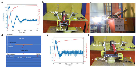
Figure 1.
Experimental tests: (a) current waveform and the corresponding action integral, (b) experimental setup, and (c) a discharge moment of the single-point injection test. (d) Schematic of the swept stroke CFRP specimen. (e) The current waveform and the corresponding action integral and (f) the experimental setup for swept stroke.
For lightning swept stroke test, impulse current with a 36 kA peak current was applied at the initial point of the tested specimen as presented in Figure 1e. Unlike the single-point current injection lightning strike test, only one side of the laminated specimen was grounded and the initial striking point was located away from the grounded edge, to simulate the current skipping during a swept stroke process (Figure 1f). The parameters of lightning currents applied in the single-point current injection tests and the swept stroke tests were summarised in Table 1.

Table 1.
Parameters of lightning current.
After the LS tests, the damaged area of the CFRP composites was examined by an air-coupled ultrasonic testing system (NAUT21) produced by Japan Probe Co., Ltd. (Hokkaido, Japan). The ultrasonic frequency was set as 400 kHz. The damage depth was detected by a non-destructive B-scan testing method with an OMNISCAN-X3 16:64 PR ultrasonic testing system produced by Olympus Co., Ltd., Richmond Hill, ON, Canada. The ultrasonic frequency was set to 10 MHz.
3. FE Model
A single-point current injection FE model of CFRP laminates was developed, as shown in Figure 2a. The CFRP laminates with a layup sequence of [45/0/−45/90]2s had a dimension of 200 mm × 200 mm × 3 mm, consistent with the test specimens. A surface current was applied at the centre of the laminates with a 5 mm radius arc channel attachment area, as reported in the literature [25,26,27,28]. Note that arc channel area was assumed to be constant during the simulation, indicating that the arc channel was stationary. In practice, lightning arc channel evolution is strongly influenced by the material used and its surface coating and electrical conductivity [30]. Four side surfaces of the CFRP laminate were set as zero potential to simulate the grounding condition. All free surfaces of the FE model were subject to thermal radiation conditions with a radiation coefficient of 0.85 and the ambient temperature was set as 25 °C. The theoretical modelling of the proposed coupled thermal-electrical FE model was detailed in our previous work [22]. In addition, the corresponding material properties were listed in Table 2. In addition, a latent heat of vaporisation was introduced in the FE model to ensure that the temperature of the CFRP composite lower than the sublimation temperature of 3316 °C [36]. The assumption was rational as the energy dissipated by the latent heat would be released in the form of mechanical damage in the test. The analysis time was set as 70 µs. The mesh density of 5 mm was selected to obtain an accurate result at a low computational cost after a mesh sensitivity analysis. The element type of FE models was 8-node linear coupled thermal-electrical continuum brick elements DC3D8E [22]. The electrical conductivity of materials increases rapidly when the electrical field exceeds the dielectric strength. Therefore, the status of dielectric breakdown of materials was monitored by a user subroutine in ABAQUS with a flow chart described in Figure 2c. In this case, the breakdown strength of CFRP ply was 33.4 kV/mm, aligned with the value from the literature [11,22]. In each step of the analysis, a comparison was made between the potential gradient (E) and the breakdown strength (DE). If the condition of |E| > DE was met, the electrical conductivity of the resin was raised by a factor of 1,000,000 [22].
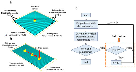
Figure 2.
FE mesh and boundary conditions: (a) single-point current injection and (b) swept stroke FE models. (c) Flowchart of FE model with a user subroutine.
Table 2.
Material properties of CFRP composites [22].
The swept stroke FE model (Figure 2b) was developed in a similar manner to the single-point current injection FE model as shown in Figure 2a. The dimensions of the swept stroke FE model were 400 mm × 200 mm × 3.2 mm. Zero electrical potential was applied on one side surface of the laminate, consistent with the grounding condition of the swept stroke test. FE analyses were conducted with a current magnitude of 36 kA. The spacing of the three attachment points is 100 mm. The dwell time of the lightning channels was considered in the Section 4.3. The waveform of the experimental lightning current is an approximate double exponential curve with the parameter T1/T2 = 34.6/56.5 μs. The front time T1 is the time between the virtual origin and the point of intersection of a straight line through points at 30% and 90% of the peak amplitude. Decay time T2 is taken to be the time to decay 50% of the peak amplitude. The current waveforms applied in the FE models are consistent with the corresponding experimental results as listed in Table 1.
After the FE analysis, the lightning-damaged area of the composites was approximated by the matrix pyrolysis area where local temperature was greater than the matrix pyrolysis temperature (i.e., 510 °C), according to our previous thermogravimetric testing results [37].
4. Results and Discussion
4.1. Lightning Damage under Single-Point Current Injection
Lightning strike tests of each single-point injection and swept stroke were conducted once. Figure 3a shows the lightning damage on the CFRP laminate after a 112 kA single-point current injection. Intense fiber damage (elliptical in shape) was localized near the lightning attachment location and aligned along the top layer’s fiber direction (45°), i.e., the shortest conduction path. When a lightning current passes through the CFRP composite, a large amount of resistive heating is generated on the CFRP composites due to the low electrical conductivity of CFRP composites. Therefore, the area near the lightning attachment point is intensely damaged with the failure modes of fibre breakage and matrix decomposition. The lightning damage in the laminate is evaluated by ultrasonic C-scan image (Figure 3b) and is compared with that by the FE model (Figure 3c). It is found that the shape and area of the lightning damage predicted by the FE model is comparable to that by the experiment results. The experimental damage area was measured to be 7275 mm2, which is 10.0% smaller than the FE-predicted damaged area of 8085 mm2. Figure 4 compares the damage depths of the CFRP laminates obtained from the experiment and FE model. Yellow lines ‘A1-A2’ and ‘B1-B2’ in experimental and modelling tests indicate section lines along the horizontal and vertical directions at the lightning strike point. The largest experimental damage depth of the CFRP composite is 0.85 mm, which is 22% lower than that predicted by the FE model (1.09 mm). The FE results are slightly lower than those by the lightning strike experiments.
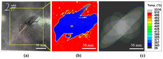
Figure 3.
In-plane lightning damage in CFRP composites under 112 kA single-point current injection: (a) visual inspection, (b) ultrasonic C-scan results, and (c) FE model prediction.
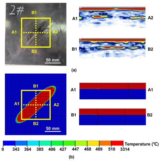
Figure 4.
Through-thickness lightning damage in CFRP composites under 112 kA single-point current injection: (a) visual inspection and ultrasonic C-scan results and (b) FE model prediction.
4.2. Lightning Damage under Swept Stroke
The lightning damage to CFRP laminates under a 36 kA swept stroke is shown in Figure 5a,b. It is worth noting that during the swept stroke experiment, the embedded copper wire remains intact after the test. This indicates that all applied current flows from the initial attachment to the last attachment. The results also show that the lightning damage in the CFRP composites decreases with an increase of the distance to the initial attachment point, i.e., the greatest damage in the 1st attachment point and the smallest damage in the 3rd attachment point. This infers that the injected electrical energy is mostly dissipated around the initial attachment region. The rough approximations of the lightning-damaged areas at each attachment location are 3689 mm2 (#1), 580 mm2 (#2) and 359 mm2 (#3). According to the electromagnetic field theory [38], high current can flow through a copper wire at 3 × 10⁸ m/s during the test. The current applied to each striking points in FE model was determined based on the damaged area observed in the experimental results. A linear relationship between the damaged area of the CFRP composite and the action integral of the applied current is stated in reference [28]. Consequently, the magnitudes of the three currents can be determined based on the ratio of the action integrals with the same waveform. Figure 5c shows the corresponding lightning damage predicted by the swept stroke FE model. The FE-predicted damaged areas at three locations are 3418 mm2 (#1), 674 mm2 (#2) and 326 mm2 (#3). These results are comparable to the experimental one, with the largest deviation of 18.7%. Figure 6 compares the visual inspection and corresponding ultrasonic C-scan images showing lightning damage penetration from the experiment and the FE model. Yellow lines ‘A1-A2, B1-B2’, ‘A3-A4, B3-B4’, and ‘A5-A6, B5-B6’ represent section views at the first, second and third lightning strike points, respectively. The maximum damage depths of the experiments (Figure 6a) at three lightning attachment points are 1.00 mm (at 5th ply), 0.67 mm (at 4th ply) and 0.94 mm (at 5th ply). However, the predicted damage depths (Figure 6b) are lower than those by experiments. For the tested laminated specimens, the lightning current is guided by a copper wire embedded inside the laminates (at 4th ply with a depth of ~0.8 mm) at three points. The current was injected directly inside the laminate, which may have led to the difference in the damage depth between the FE model and the experiments.
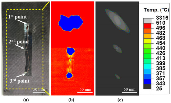
Figure 5.
In-plane lightning damage in CFRP composites under 36 kA swept stroke: (a) visual inspection, (b) ultrasonic C-scan results and (c) FE model prediction. Note that all three lightning attachment points are connected through a thin copper wire in (a).
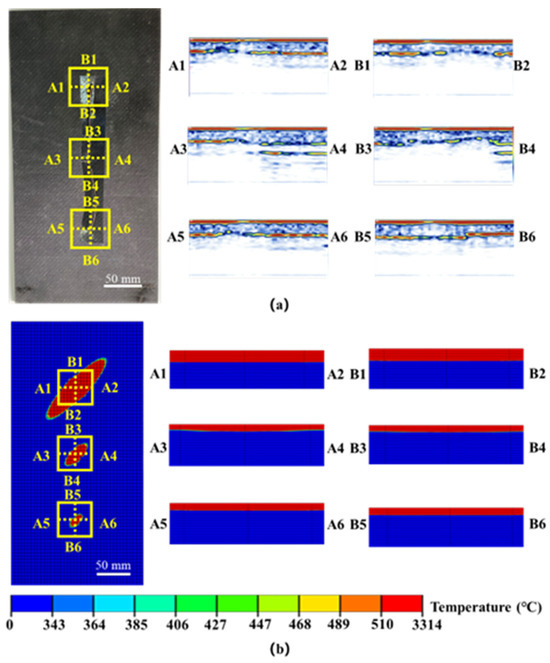
Figure 6.
Through-thickness LS damage in CFRP composites under swept stroke: (a) Visual inspection and ultrasonic C-scan results and (b) FE model prediction.
The relationship between the total damaged area and the action integrals of the current waveforms used in the FE model were calculated and the results are shown in Figure 7. The varying action integrals are achieved by adjusting the peak current of the lightning current waveform, and the parameters used in the FE models are listed in Table 3. The total lightning-damaged area is linearly proportional to the action integrals of the current waveform during a single-point current injection, which is consistent with the literature [25]. As shown in the figure, the predicted damaged area from the swept stroke model is much larger than that of a single-point current injection, even though they have the same action integrals.
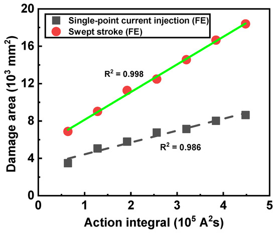
Figure 7.
Relationship between lightning damage and action integral from a single-point current injection and swept stroke FE models.
Table 3.
Lightning current parameters.
4.3. Parametric Analysis
The swept stroke FE model was further used to understand the damage to a CFRP composite panel in a moving aeroplane. The skip distance and dwell time of lightning channels are dependent on the moving speed of the aeroplane [15]. Table 4 contains the skip distances and dwell times from the literature [15]. Those for the cruise speed of a typical commercial aeroplane (i.e., 255 m/s) were approximated through the exponential extrapolation of the data defined over the flow speed range (25–75 m/s). As shown in Figure 8, the values of the skip distance and dwell time are obtained by fitting the curve to a value of 0.02 m and 5.0 × 10⁻³ ms when the moving speed is 255 m/s.
Table 4.
Skip distances and dwell times at different flying speeds.
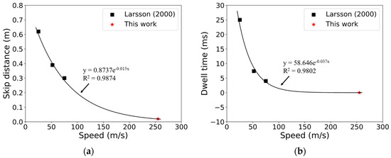
Figure 8.
(a) Skip distance and (b) dwell time as a function of a cruising speed. The values for 255 m/s (typical airliner cruise speed) were approximated by the exponential extrapolation of the data defined over the flow speed range.
Additional swept stroke FE models were developed for the laminate with the dimensions of 400 mm × 200 mm × 3.2 mm. The skip distance of 0.02 m, and the dwell time of 0.005 ms. The 112 kA swept stroke FE model was considered herein to produce noticeable responses to a laminate. Figure 9a shows the evolution of electrical potential distributions in the outermost +45° ply of the laminate during a 112 kA swept stroke. ‘#1’ and ‘#2’ indicate the first and second lightning strike points in the FE model. A high electrical potential is noticeable with a narrow elliptical shape at an angle of 45°. At 6 μs, when the electrical current is injected to the second attachment point, the shape of the high electrical potential is altered to an oval shape. After that, the electrical potential coupling effect between the two attachment points are evident. At 34 μs, the electrical potential reaches to the peak (16 kV). Subsequently, the electrical potential decreases dramatically due to current dissipation and a decrease in the applied electrical current. Figure 9b presents the projected damaged area by single-point current injection and swept stroke. The damage at the surface is located along the 45° direction because of the high electrical conductivity in that direction. The lightning damaged area under swept stroke expands to the left grounded edge (i.e., zero electrical potential). The swept stroke FE model prediction suggests that the electrical potential distributions (Figure 9a) and corresponding lightning damage (Figure 9b) to a CFRP laminate are highly influenced by the coupling between two adjacent lightning attachments.
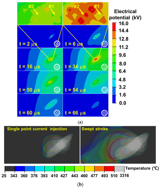
Figure 9.
(a) Electrical potential distribution contours in the CFRP’s top ply under 112 kA swept stroke with two lightning attachment points. (b) Projected lightning-damaged areas of CFRP composite under single-point current injection stroke and swept stroke.
The electrical potential coupling effect is dependent on the skip distance and the applied current amplitude of lightning channels. A parametric study on the swept stroke FE model was performed to examine the effect of skipping distance and current magnitude on lightning damage in a CFRP laminate. Figure 10 shows the schematic of the swept stroke FE model developed with two different approaches: (1) the single swept stroke and (2) the superposition of two single-point current injection. The first approach (Figure 10a) is a swept stroke model with two attachment points (0.02 m skip distance and 0.005 ms dwell time from Table 4). The second approach (Figure 10b) is a superposed model that two single-point current injection FE models are performed with an attachment point at point 1 (from 0 ms) and point 2 (from 0.005 ms). In this case, local electrical potential and thus the temperature are calculated from each of two current injections, and they have coupled each other. Figure 11 shows the electrical potential at the initial attachment point of the laminate (point 1) in the thickness direction predicted from 11.2 and 112 kA swept strokes, respectively. At 11.2 kA swept stroke, the predicted electrical potentials by the swept stroke FE model (Figure 10a) are the same with those by the superposed FE model (Figure 10b), indicating that the coupling effect between two adjacent lightning attachment points is insignificant. In contrast, at 112 kA swept stroke, the results predicted by the swept stroke FE model are different from those by the superposed FE model up to the penetration depth of 1.2 mm. This indicates that the electrical potential coupling effect should be considered.
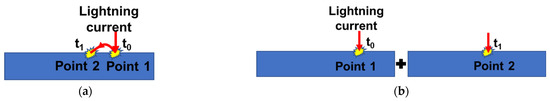
Figure 10.
Schematic of swept stroke FE models: (a) the swept stroke model and (b) the superposition model.
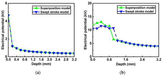
Figure 11.
Through-thickness electrical potential variation at the initial point during a swept stroke with a peak current of (a) 11.2 kA and (b) 112 kA.
To quantify the skip distance and current magnitude on the coupling effect, the coefficient of determination (denoted R2) was calculated as follows:
where is the value of the electrical potential by the superposed model as shown in Figure 10b at point 1 in the in-depth direction. is the value of the electrical potential by the sweep stroke FE model as shown in Figure 10a along the same path. is the average value of the . As depicted in Figure 11a, the relationship between R2 and the peak current when the skip distance is set as 20 mm. The R2 is nearly equal to 1 up to 56 kA, indicating that the results obtained by the sweep stroke model (Figure 10a) are equivalent to those from the superposed single-point current injection FE model Figure 10b. However, once the magnitude of the applied current is greater than 56 kA, the R2 drops to 0.75 and remains at a stable range between 0.7 and 0.8 with the increase of peak current. This suggests that the coupling effects become significant at higher peak current (>56 kA) coupled with 20 mm skip distance, thus the swept stroke approach (Figure 10a) must be employed to predict electrical potentials and corresponding lightning damage. Figure 12b illustrates the relation between the R2 and the skip distance under a peak current of 112 kA. The R2 was equal to 1 when the skip distance is greater than 40 mm, which indicates that the coupling effect is insignificant. When the distance between strike points is smaller than 35 mm, the coupling effect is significant and swept stroke FE model should be considered in the lightning damage prediction.
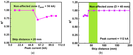
Figure 12.
Relationship between R2 and: (a) peak current magnitude and (b) skip distance defined in the swept stroke model.
This section examined the electrical potential evolution and the corresponding damage of a composite panel in a moving aeroplane under a swept stroke and the effect of skipping distance and current magnitude on lightning damage in a CFRP laminate. The results provide guidance for designing aircraft CFRP composite against swept stroke.
5. Conclusions
In this study, the lightning damage behaviour of CFRP composites under swept stroke has been studied through both experimental methods and FE modelling. The following conclusions can be drawn:
- (1)
- The swept stroke FE model was developed to predict the lightning damage, and the model prediction was comparable to that by experiments with a deviation of less than 23%.
- (2)
- The FE results showed that the swept stroke-induced lightning damage in a CFRP composite was linearly proportional to the action integral of the current waveform.
- (3)
- Both the swept strike tests and corresponding FE models showed that total lightning damage to the CFRP composites decreases with an increase in the distance from the initial attachment point. The majority of the injected electrical energy is dissipated around the initial attachment region, thus causing the most severe damage to that location.
- (4)
- The coupling effect of electrical potential and lightning damage between each attachment point was strongly dependent on the skip distance and the applied current magnitude. The coupling effect was insignificant when the skip distance is large and the current magnitude is low.
Author Contributions
Conceptualization, C.K. and K.F.; Methodology, K.F.; Investigation, C.K.; Writing—original draft, C.K.; Writing—review & editing, K.F. and X.C.; Formal analysis, J.L. and H.Z.; Funding acquisition, K.F.; Resources, K.F. and Q.S. All authors have read and agreed to the published version of the manuscript.
Funding
The authors acknowledge the financial support from the National Natural Science Foundation of China (grant no. 12172257) and the National Science and Technology Major Project, China (grant no. J2019-VIII-0009-0170).
Institutional Review Board Statement
Not applicable.
Informed Consent Statement
Not applicable.
Data Availability Statement
Data are contained within the article.
Conflicts of Interest
Author Qizhen Shi was employed by the company Aero Engine Corporation of China. The remaining authors declare that the research was conducted in the absence of any commercial or financial relationships that could be construed as a potential conflict of interest.
References
- Lee, J.; Gharghabi, P.; Boushab, D.; Ricks, T.M.; Lacy, T.E.; Pittman, C.U.; Mazzola, M.S.; Velicki, A. Artificial lightning strike tests on PRSEUS panels. Compos. Part B Eng. 2018, 154, 467–477. [Google Scholar] [CrossRef]
- Chakravarthi, D.K.; Khabashesku, V.N.; Vaidyanathan, R.; Blaine, J.; Yarlagadda, S.; Roseman, D.; Zeng, Q.; Barrera, E.V. Carbon Fiber-Bismaleimide Composites Filled with Nickel-Coated Single-Walled Carbon Nanotubes for Lightning-Strike Protection. Adv. Funct. Mater. 2011, 21, 2527–2533. [Google Scholar] [CrossRef]
- Zhang, X.; Cheng, X.; Hei, Y.; Xing, L.; Li, Z. Lightning strike damage on the composite laminates with carbon nanotube films: Protection effect and damage mechanism. Compos. Part B Eng. 2019, 168, 342–352. [Google Scholar] [CrossRef]
- Marsh, G. Airbus A350 XWB update. Reinf. Plast. 2010, 54, 20–24. [Google Scholar] [CrossRef]
- Kumar, V.; Yokozeki, T.; Okada, T.; Hirano, Y.; Goto, T.; Takahashi, T.; Ogasawara, T. Effect of through-thickness electrical conductivity of CFRPs on lightning strike damages. Compos. Part A Appl. Sci. Manuf. 2018, 114, 429–438. [Google Scholar] [CrossRef]
- Sun, J.; Yao, X.; Huang, Y.; Jiao, Z.; Chen, J. Experimental and numerical analysis of damage characteristics to opgw strands under first lightning strike and continuous current. Electr. Power Syst. Res. 2020, 187, 106515. [Google Scholar] [CrossRef]
- Senis, E.C.; Golosnoy, I.O.; Dulieu-Barton, J.M.; Thomsen, O.T. Enhancement of the electrical and thermal properties of unidirectional carbon fibre/epoxy laminates through the addition of graphene oxide. J. Mater. Sci. 2019, 54, 8955–8970. [Google Scholar] [CrossRef]
- Brown, S.; Robert, C.; Koutsos, V.; Ray, D. Methods of modifying through-thickness electrical conductivity of CFRP for use in structural health monitoring, and its effect on mechanical properties—A review. Compos. Part A Appl. Sci. Manuf. 2020, 133, 105885. [Google Scholar] [CrossRef]
- Zhang, D.; Ye, L.; Deng, S.; Zhang, J.; Tang, Y.; Chen, Y. CF/EP composite laminates with carbon black and copper chloride for improved electrical conductivity and interlaminar fracture toughness. Compos. Sci. Technol. 2012, 72, 412–420. [Google Scholar] [CrossRef]
- Newcomb, B.A.; Chae, H.G. 21—The properties of carbon fibers. In Handbook of Properties of Textile and Technical Fibres, 2nd ed.; Bunsell, A.R., Ed.; Woodhead Publishing: Sawston, UK, 2018; pp. 841–871. [Google Scholar] [CrossRef]
- Zhu, H.; Fu, K.; Yang, B.; Li, Y. Nickel-coated nylon sandwich film for combination of lightning strike protection and electromagnetic interference shielding of CFRP composite. Compos. Sci. Technol. 2021, 207, 108675. [Google Scholar] [CrossRef]
- Uman, M.A.; Rakov, V.A. The interaction of lightning with airborne vehicles. Prog. Aerosp. Sci. 2003, 39, 61–81. [Google Scholar] [CrossRef]
- Huang, L.; Gao, C.; Guo, F.; Sun, C. Lightning Indirect Effects on Helicopter: Numerical Simulation and Experiment Validation. IEEE Trans. Electromagn. Compat. 2017, 59, 1171–1179. [Google Scholar] [CrossRef]
- Larsson, A.; Lalande, P.; Bondiou-Clergerie, A.; Delannoy, A. The lightning swept stroke along an aircraft in flight. Part I: Thermodynamic and electric properties of lightning arc channels. J. Phys. D Appl. Phys. 2000, 33, 1866–1875. [Google Scholar] [CrossRef]
- Larsson, A.; Lalande, P.; Bondiou-Clergerie, A. The lightning swept stroke along an aircraft in flight. Part II: Numerical simulations of the complete process. J. Phys. D Appl. Phys. 2000, 33, 1876. [Google Scholar] [CrossRef]
- Broc, A.; Lalande, P.; Montreuil, E.; Moreau, J.-P.; Delannoy, A.; Larsson, A.; Laroche, P. A lightning swept stroke model: A valuable tool to investigate the lightning strike to aircraft. Aerosp. Sci. Technol. 2006, 10, 700–708. [Google Scholar] [CrossRef]
- Ma, X.; Wang, F.; Chen, H.; Wang, D.; Xu, B. Thermal damage analysis of aircraft composite laminate suffered from lightning swept stroke and arc propagation. Chin. J. Aeronaut. 2020, 33, 1242–1251. [Google Scholar] [CrossRef]
- Chemartin, L.; Lalande, P.; Peyrou, B.; Chazottes, A.; Elias, P.Q.; Delalondre, C.; Cheron, B.G.; Lago, F. Direct effects of lightning on aircraft structure: Analysis of the thermal, electrical and mechanical constraints. Aerosp. Lab. 2012, 5, 1–15. [Google Scholar]
- Wang, Y.; Zhupanska, O. Lightning strike thermal damage model for glass fiber reinforced polymer matrix composites and its application to wind turbine blades. Compos. Struct. 2015, 132, 1182–1191. [Google Scholar] [CrossRef]
- Chemartin, L.; Lalande, P.; Montreuil, E.; Delalondre, C.; Chéron, B.; Lago, F. Three dimensional simulation of a DC free burning arc. Application to lightning physics. Atmos. Res. 2009, 91, 371–380. [Google Scholar] [CrossRef]
- Dobbing, J.A.; Hanson, A.W. A swept stroke experiment with a rocket sled. In Proceedings of the 1978 IEEE International Symposium on Electromagnetic Compatibility, Atlanta, GA, USA, 20–22 June 1978; pp. 1–6. [Google Scholar]
- Fu, K.; Ye, L.; Chang, L.; Yang, C.; Zhang, Z. Modelling of lightning strike damage to CFRP composites with an advanced protection system. Part I: Thermal–electrical transition. Compos. Struct. 2017, 165, 83–90. [Google Scholar] [CrossRef]
- Feraboli, P.; Kawakami, H. Damage of Carbon/Epoxy Composite Plates Subjected to Mechanical Impact and Simulated Lightning. J. Aircr. 2010, 47, 999–1012. [Google Scholar] [CrossRef]
- Guo, Y.L.; Dong, Q.; Chen, J.L.; Yao, X.L.; Yi, X.; Jia, Y. Comparison between temperature and pyrolysis dependent models to evaluate the lightning strike damage of carbon fiber composite laminates. Compos. Part A Appl. Sci. Manuf. 2017, 97, 10–18. [Google Scholar] [CrossRef]
- Ogasawara, T.; Hirano, Y.; Yoshimura, A. Coupled thermal–electrical analysis for carbon fiber/epoxy composites exposed to simulated lightning current. Compos. Part A Appl. Sci. Manuf. 2010, 41, 973–981. [Google Scholar] [CrossRef]
- Abdelal, G.; Murphy, A. Nonlinear numerical modelling of lightning strike effect on composite panels with temperature dependent material properties. Compos. Struct. 2014, 109, 268–278. [Google Scholar] [CrossRef]
- Liu, Z.Q.; Yue, Z.F.; Wang, F.S.; Ji, Y.Y. Combining analysis of coupled electrical-thermal and blow-off impulse effects on composite laminate induced by lightning strike. Appl. Compos. Mater. 2015, 22, 189–207. [Google Scholar] [CrossRef]
- Hirano, Y.; Katsumata, S.; Iwahori, Y.; Todoroki, A. Artificial lightning testing on graphite/epoxy composite laminate. Compos. Part A Appl. Sci. Manuf. 2010, 41, 1461–1470. [Google Scholar] [CrossRef]
- Martins, R.S.; Chemartin, L.; Zaepffel, C.; Lalande, P.; Soufiani, A. Electrical and hydrodynamic characterization of a high current pulsed arc. J. Phys. D Appl. Phys. 2016, 49, 185204. [Google Scholar] [CrossRef]
- Lee, J.; Lacy, T.E., Jr.; Pittman, C.U., Jr. Coupled thermal electrical and mechanical lightning damage predictions to carbon/epoxy composites during arc channel shape expansion. Compos. Struct. 2021, 255, 112912. [Google Scholar] [CrossRef]
- Millen, S.; Murphy, A.; Abdelal, G.; Catalanotti, G. Sequential finite element modelling of lightning arc plasma and composite specimen thermal-electric damage. Comput. Struct. 2019, 222, 48–62. [Google Scholar] [CrossRef]
- Karch, C.; Arteiro, A.; Camanho, P. Modelling mechanical lightning loads in carbon fibre-reinforced polymers. Int. J. Solids Struct. 2018, 162, 217–243. [Google Scholar] [CrossRef]
- Lee, J.; Lacy, T.E., Jr.; Pittman, C.U., Jr. Lightning mechanical damage prediction in carbon/epoxy laminates using equivalent air blast overpressure. Compos. Part B Eng. 2021, 212, 108649. [Google Scholar] [CrossRef]
- Feraboli, P.; Miller, M. Damage resistance and tolerance of carbon/epoxy composite coupons subjected to simulated lightning strike. Compos. Part A Appl. Sci. Manuf. 2009, 40, 954–967. [Google Scholar] [CrossRef]
- Millen SL, J.; Murphy, A. Understanding the influence of test specimen boundary conditions on material failure resulting from artificial lightning strike. Eng. Fail. Anal. 2020, 114, 104577. [Google Scholar] [CrossRef]
- Griffis, C.; Nemes, J.; Stonesifer, F.; Chang, C. Degradation in Strength of Laminated Composites Subjected to Intense Heating and Mechanical Loading. J. Compos. Mater. 1986, 20, 216–235. [Google Scholar] [CrossRef]
- Luo, T.; Li, Y.; Fu, K.; Yang, B.; Li, Y. Artificial Neutral Network-based Integrity Analysis of Carbon Fiber Reinforced Polymer Composites After High-Temperature Exposure. Appl. Compos. Mater. 2022, 30, 41–55. [Google Scholar] [CrossRef]
- Teixeira, F.L.; Moreira, F.J.S.; Pereira-Filho, O.M.C. Electromagnetic Wave Propagation. In Encyclopedia of RF and Microwave Engineering; Chang, K., Ed.; Wiley: Hoboken, NJ, USA, 2005. [Google Scholar]
Disclaimer/Publisher’s Note: The statements, opinions and data contained in all publications are solely those of the individual author(s) and contributor(s) and not of MDPI and/or the editor(s). MDPI and/or the editor(s) disclaim responsibility for any injury to people or property resulting from any ideas, methods, instructions or products referred to in the content. |
© 2023 by the authors. Licensee MDPI, Basel, Switzerland. This article is an open access article distributed under the terms and conditions of the Creative Commons Attribution (CC BY) license (https://creativecommons.org/licenses/by/4.0/).