Abstract
This work aims to study the relation between the hardness and behavioral wear of tungsten carbide inserts (TCI) and polycrystalline diamond compact (PDC) cutters, used as drill bits for drilling oil and gas wells, through wear testing conducted using the pin-on-disc test and the measure of microhardness Knoop test. The morphology of the worn surface was characterized using scanning electron microscopy (SEM), and the chemical composition was taken before and after the wear test inside the tracks using energy-dispersive X-ray spectrometry (EDX). Additionally, the behavior of the corrosion resistance was evaluated with the electrodynamic polarization technique and was compared with a coating of diamond-like carbon (DLC) in order to determine whether this coating applied to tool steel could serve as a substitute for insert-based coatings in future applications, as its cost is lower than that of the inserts. A paragraph discusses what characteristics must be taken when selecting or manufacturing materials for drill bit applications. In conclusion, it was found that the TCI insert presented cracks in the test tracks, while the PDC insert showed soft wear; this was due to the uncertain hardness, which was greater than the indenter used. Concerning the Tafel test, the curves showed that the PDC insert presents better behavior under corrosion; however, the DLC can be a good substitute.
1. Introduction
When considering material selection and sintering for drill bit applications, specifically in the petrochemical industry, many variables must be considered; we can consider tensile strength, fatigue resistance, hardness, the modulus of elasticity, toughness, fracture resistance, and the expansion coefficient, among others. In a general sense, the component used in drill bits for oil or gas wells is the auger at the tip that removes the material. These drill bits can be, among other options, fixed cut bits (also known as drag bits), which are commercially called polycrystalline diamond compact (PDC) bits; these have built-in cutters that rotate together. This type of drill bit cuts soft formations into a plowshare, gouging or indenting the ground. Modern fixed-cut drills with surface diamond (PDC) bits cut rock in a similar way to a lathe. Their superior abrasion resistance is seen as the main contributor to the greatly improved drilling efficiency and economy [1]. Another type of drill bit is a rotary taper bit, which has metal cones that rotate independently as the drill rotates. Each cone has cutting structures (wear-resistant steel teeth or TCI tungsten carbide inserts) that cut and grind or plunge and break, much like chisels or spades, depending on the hardness of the formation [2]. Together, different types of drill bits, in the process of working, are not only subject to wear processes, but are also in contact with chemically aggressive environments, meaning that corrosion can play a pivotal role in the degradation of the surface and can significantly accelerate wear [3]. Furthermore, despite their extensive use and excellent abrasion resistance, PDC tools are still very susceptible to fractures [4,5,6,7,8,9]; this is why the development of the wearing surface of PDC and TCI bits is one of the most crucial problems in drilling industries, considering that excessive costs can result from the improper choice (or design) of the cutting tool [10]. This is mainly a result of their relatively low fracture toughness [1] and because the bit wear is considered an intrinsic cost, although significant savings are achievable through the effective control and minimization of the bit wear [11]. Finally, although there are various wear studies on PDC drill bits and on TCI uncertainties, there is no information on their corrosion behavior [4,5,6,7,8,9,11]. For this reason, the objective of this research is to determine the relation between microhardness and abrasion wear on two bodies through the pin-on-disc test. Additionally, to determine the wear mechanism, SEM electron microscope micrographs were compared after the wear test with studies simulating the conditions of use of these drill bits. Also, polarization curves were used to determine the corrosion behavior. One of the reasons for carrying out the corrosion test is based on what has been stated by Human et al. [3], who report that there is a considerable amount of research on the corrosion of cemented carbides, but that this has been largely limited to comparisons of the corrosion rates in different solutions using measures of weight loss. Furthermore, there have been a few studies aimed at understanding the processes involved, and all of them have made use of electrochemical measurements. Consequently, satisfactory explanations of the corrosion mechanisms that occur are lacking. The relationship between microstructural parameters and corrosion is unclear, and researchers have reported very high experimental variations, making comparisons between grades of different tungsten carbide grain sizes and binder contents inconclusive. Another reason is mentioned by Zeng et al. [12], who comment that, with the exploitation of oil and gas in high-quality oil fields entering the middle and late stages, the high content of water and Cl- in the produced water, as well as the high partial pressure of corrosive gases such as CO2 and H2S in transmission pipelines, lead to extremely severe corrosion damage, resulting in the thinning of the walls and even the perforation of the pipelines, causing huge economic losses and serious environmental pollution. Moreover, no reports of Tafel curves were found for the PDI inserts, and a comparison between these inserts was desired. Finally, a paragraph discusses the selection of materials for the use of drill bits so that future investigations might have information on the necessary characteristics when selecting materials for these applications. One of these materials is the diamond-like carbon, or DLC, coating for tool steels, which has good mechanical properties [13,14,15,16] and decreases production costs compared to the costs of PCI and TCI.
2. Selection of Cutting Materials
According to Ashby [17], the materials used to make cutting tools are high-carbon steels and ceramics such as NSi and W3C, using Co as a binder. Tungsten carbides are used because approximately 25% of the annual production of tungsten is converted into mill products, and another 60% is used in cutting tools in the form of tungsten carbides; this is because they are rigid, hard, and abrasion-resistant. They also retain their resistance to high temperatures and resist corrosion, hence their use in cutting tools [18].
According to existing classifications, the three most used types of drill bits correspond to rotary cutter bits with TCI inserts, fixed PDC cutters, and impregnated diamond drill bits [19]. The latter are known as diamond-like carbon (DLC) bits, which are manufactured using different techniques, among the most relevant of which are physical vapor deposition (PVD) and chemical vapor deposition (CVD). Currently, plasma-enhanced chemical vapor deposition (PECVD) is used, which helps to lower deposition temperatures [19].
Figure 1a shows a rotary Tricone drill bit that was invented in 1933 and rotates independently as the drill rotates with tungsten carbide inserts, and Figure 1b shows fixed-cut drill bits, also known as drag bits, with polycrystalline compact diamond inserts. This was the beginning of the use of synthetic materials for improving the performance of drilling bits [10,20].
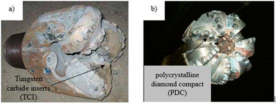
Figure 1.
(a) Tricone drill bits with tungsten carbide inserts. (b) Improving performance using synthetic materials with polycrystalline compact diamond. Photo from public domain [20].
In the drilling of wells for the extraction of oil and gas, the two most commonly used types of drill bits are tungsten carbide inserts (TCI) and fixed-cut polycrystalline diamond compact (PDC) drill bits, such as those shown in Figure 2:
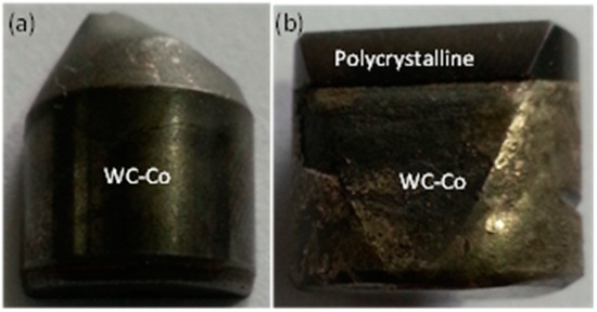
Figure 2.
Cutters employed: (a) TCI cutter; (b) PDC cutter used in this research.
2.1. Triconic Bits with TCI
They consist of three cutting cones that rotate on their own axis. They vary according to the cutting structure; they can have milled steel teeth or tungsten carbide inserts and change according to their bearing system. In these bits, the manufacturer inserts hard tungsten carbide inserts by applying pressure in holes drilled in the drill cone. Their lifetime is longer because tungsten carbide is more resistant to wear during drilling than steel. WC properties such as the hardness, wear area, tooth impact resistance, cracking time, and microstructure characteristics are a function of grain size [21]. Fine-grained carbides exhibit the best abrasion resistance. Coarse-grained carbides optimize the impact toughness. Ultra-fine-grained carbides provide excellent wear resistance and anti-impact toughness. Thus, the impact and abrasion resistance of the teeth can be significantly improved.
2.2. PDC Cutters
PDC fixed-cutter drill bits are widely used in oil and gas well drilling. Their abrasion resistance is seen as the main contributor to their improved drilling efficiency. These cutters are composed of a layer of polycrystalline diamond bonded in situ on a tungsten carbide substrate [21]. PDC cutters are welded to the bit after being bonded to the body, and their main purpose is to obtain a longer-lasting and more wear-resistant cutter. The PDC cutter fractures the rock via cutting. During this action, the direction of the load and the resulting fracture are approximately parallel. As the cutter penetrates the formation, the cutter tip cuts and removes the material in layers [22]. The disadvantage that affects the PDC cutter’s performance is the cobalt content because it is used as a catalyst to facilitate the sintering of the diamond grains, which in turn is detrimental to the hardness and thermal stability; this is due to unwanted tungsten carbide phases that weaken the diamond structure, and thus the diamond grain size and residual stress distribution that affect abrasion resistance [23]. An important concept to understand is the effect of the diamond grain size. In general, if the initial grit is between 1 and 6 µm, the resulting cutter will have relatively high abrasion resistance but relatively poor impact resistance. In contrast, a PDC cutter manufactured with a coarse grit diamond grit > 16 µm will have relatively low abrasion resistance but high impact resistance. In between these two extremes, cutters using a medium diamond grit size between 7–15 µm show moderate abrasion and medium impact resistance.
3. Materials and Methods
Several tests were carried out to evaluate the wear and corrosion resistance of two types of materials used in drill bit cutters for oil and gas well drilling. The tests performed, as well as the equipment, instrumentation, and configuration used in each one, are described below.
The study materials were tungsten carbide inserts (TCI) used in a 12 ¼” tri-cone drill bit and 12 ¼” PDC fixed-cutter bits. The TCI cutters were a sintered material consisting of tungsten carbide (WC) crystals bonded via a cobalt-based binder. Typically, the composition of the blends ranges from 6% to 18% cobalt. In our case, this was 6% by weight; see Figure 2a. The PDC cutters had a diameter of 16 mm: the tungsten carbide cylinder was 10 mm high, and the diamond layer was 2 mm thick. These cutters were sintered using HP–HT (high pressure and high temperature), at a temperature of over 1400 °C and a pressure of approximately 5.5 GPa. These cutters were composed of a layer of polycrystalline diamond bonded in situ onto a tungsten carbide substrate, as shown in Figure 2b. The bonding was completed during a high-pressure and high-temperature sintering process. The polycrystalline diamond layer was also created during this process to form a sintered material characterized by strong diamond-to-diamond bonding [1]. Commonly, the proportion of cobalt can represent 6%–18% of the weight in the tungsten carbide substrate and 2%–8% of the weight in the diamond part [10].
The microhardness of the tungsten carbide inserts and polycrystalline compact diamond cutters was evaluated with a LECO M 400-G2 Hardness Tester (St. Joseph, MI, USA), using a Knoop hardness indenter with a 500 g load for the tungsten carbide inserts, a 2 kg load for the polycrystalline compact diamond cutters for 20 s, and a 500× optic to locate the indentations.
The tribometer equipment used for the pin-on-disc test was A CETR-UMT-2-110 (San Jose, CA, USA). The test was performed using an Al2O3 ball with a hardness of 13.41 GPa. The test parameters were as follows: a load of 3.2 N, a speed of 10 cm/s, and a duration of 600 s. The volume was calculated with (1), according to the Hincapié methodology [24,25]:
where:
V = (π × 〖Rp × (A)〗^3)/(6 × Re)
- V is the displaced volume (mm3);
- A is the width of the track (mm);
- Rp is the radius of the track (3.67 mm);
- Re is the radius of the sphere (3.18 mm).
The Rp was measured with the LSM 700 laser (Jena, Germany) confocal microscope that has a 455 nm and 550 nm solid-state laser, with a maximum power of 2 mW, a horizontal resolution of 667 nm, and a vertical resolution of 290 nm.
The wear rate Q was calculated with Archard’s model [23,26,27] (2):
where:
Q = V/(S × N)
- V is the removed volume (mm3);
- S is the distance traveled (mm);
- N is the charge (N).
After performing the tribology test, the morphology of the tracks was characterized with a FEI QUANTA 200 SEM, (Hillsboro, OH, USA) taking microscopies in the secondary electron mode, in high vacuum, and with a voltage of 30 keV. This microscope is equipped with Mira3 FEG SEMsoftware, which allows the chemical composition of the sample of tungsten carbide inserts and polycrystalline compact diamond to be determined before and after the pin-on-disc test through energy-dispersive X-ray spectrometry (EDX).
To assess the corrosion resistance of the two types of cutters, namely the tungsten carbide inserts and polycrystalline compact diamond, potentiodynamic polarization tests were performed with a Gamry Reference 600 potentiostat in a 0.35% NaCl solution [28,29]. The following configuration was used in the tests: an initial potential of −0.3 V vs. Eoc (open-circuit potential), a final potential of 0.5 V vs. Eoc, a scan rate of 0.5 mV/s, and a sampling area of 0.159 cm2.
4. Results and Discussion
4.1. Hardness and Wear Test
Table 1 shows the results regarding the microhardness of the two types of cutters, namely the tungsten carbide inserts and polycrystalline compact diamond.

Table 1.
Microhardness.
In the literature, the hardness values for the PDC drill bits are 50 GPa [11] and 7064 HV (69.28 GPa) [30], and the hardness value for the TCI drill bits is 782 HV (7.69 GPa). The difference in the values may be due to the fact that the hardness, depending on the type of test, changes the results; it may also be that, since the TCI inserts use different percentages of cobalt as a binder, the results vary.
Figure 3 and Figure 4 show the SEM microscopy images at different magnifications, starting with the width of the tracks left by the pin-on-disk test and the chemical composition for the EDX of the sample out of the track. Then, the evolution of the tracks and wear mechanisms are shown, ending with the shape of the wear left in detail and the chemical composition of the tracks.
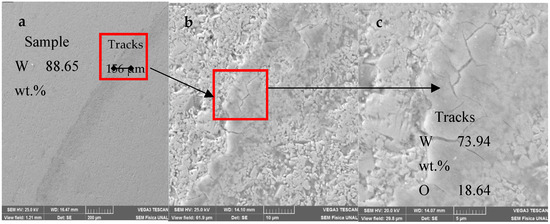
Figure 3.
(a–c) Microscopy SEM at different magnifications: (a) chemical composition of the substrate; (b) chemical composition of tracks with cracks in the TCI cutter.
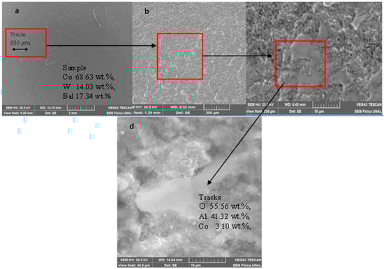
Figure 4.
(a–d) Microscopy SEM at different magnifications: (a) chemical composition in the substrate (d) chemical composition in the substrate in the tracks with Smooth wear on in PDC sample.
Figure 3a shows the chemical composition of the TCI samples with a concentration of W 88.65 wt.%, Co 6.66 wt.% and O 4.69 wt.% before the pin-on-disk test. For the TCI sample, the wear mechanism was oxidation and cracking (red box). The oxidation process was evidenced by the chemical composition taken after the test, which was W 73.94 wt.%, O 18.64 wt.%, Co 6.30 wt.%, and Other 1.12 wt.%; this is probably due to the local heating of the sample and then a subsequent reaction with oxygen from the environment, which agrees with Edrisy et al. [31]. In addition, cracks were observed inside the track, as shown in Figure 3b,c, possibly due to the embrittlement of the tracks caused by the oxides that were generated; these possibly do not present slip planes that enable plastic deformation since the cracks do not extend. The formation of cracks is explained by Yi Zhou et al. [21], where they explain that the uneven distribution of friction results in the uneven distribution of high local temperatures and a large temperature gradient within the alloy tooth material. Because the coefficient of thermal expansion of the Co binder phase is approximately three times that of WC, stress arises from the difference between thermal expansion and cold contraction. With an increase or decrease in temperature, Co undergoes compressive or tensile stress, respectively. If the thermal stress caused by thermal expansion and contraction is greater than the flexural strength of the cemented carbide, a weakened WC/Co phase interface and weak or no adhesion between Co and WC result. The lack of support adhesion provided by the Co will result in the constant removal of the WC, and this, in turn, can produce microholes [32]. With an increase in the size of the micropores, adjacent holes are connected via the formation of microcracks. Cracks extend across the WC/Co interface and the WC phase (WC phase is brittle, has a high melting point and poor thermal fatigue resistance. Co is hard, with favorable thermal fatigue resistance, so thermal fatigue cracks form first and propagate in the hard WC phase [33]). Typical thermal fatigue turtle cracks appear where the worn area is large and subjected to sufficient heat and thermal stress. In this tribological pair, the test indenter was not embedded in the cutter; as seen in Table 1, the hardness of the TCI cutter was 12.93 GPa, and that of the indenter was 13.41 GPa. Additionally, according to the chemical composition, the presence of aluminum was not evidenced. Therefore, the wear rate was of the order of 10–8, and the coefficient of friction shown in Table 2 is from the TCI sample. No data on wear rates were found for these inserts, but research that studies wear was found [34,35].
Table 2.
Wear rate results.
Figure 4a shows the chemical composition of the PCI sample with the chemical composition before the wear test, which was Co 68.63 wt.%, 14.03 wt.%; it was not possible to accurately determine the carbon content because EDX does not have the pressure to determine the energy lines of this element. After the wear test, the chemical composition was O 55.56 wt.%, Al 41.32 wt.%. The morphology within the tracks took the form of scales. This phenomenon is explained in different investigations [4,11,36]. This research proposed that PDC cutters have four main failure modes depending on the type of wear mechanism: 1—soft wear, 2—micro-chipping, 3—severe fracture or (chipping), and 4—delamination. They attributed the smooth wear to the grinding of individual diamond crystals removed on a very fine scale, possibly even atom by atom, owing to a combination of mechanical loading and thermal degradation [36]. This type of failure is less important than other failure mechanisms because the wear is not severe, and the removal of material from PDC cutters is trivial. The process identified as soft wear is, in real life, generally experienced when drilling homogeneous formations that are strong and abrasive with bits that have a large number of cutters distributed along the face of the drill bits [36]. Figure 5 shows a micrograph taken using the confocal interferometer of the tracks; a roughness change that becomes more homogeneous is observed, evidencing that soft wear exists. In this way, the possibility of calculating the wear rate using a harder or similar material as an indenter is open, as in the study conducted by Li et al. [6], who used another PDC as an indenter; they obtained cracks in the PDC caused by fatigue cracks in the carbide that seemed to grow more in the region adjacent to the diamond layer. This is consistent with the fact that, as a result of the thermal stress caused by the manufacturing process, the diamond is in a state of residual compressive stress, while the carbide next to it is in tension. According to the tribological pair, the element that wore out was the indenter of the equipment adhering to the substrate, so that the wear rate and coefficient of friction shown in the table correspond to the indenter. In the literature, the value wear rate is 9.6 × 10⁻⁹ mm, 3 N−1 m−1 [23], and the coefficient of friction is 0.45 [30]. This is explained by the difference in hardness, which, according to Table 1 for the PDC, is 39.93 Gpa; this exceeds three times the hardness of the indenter.
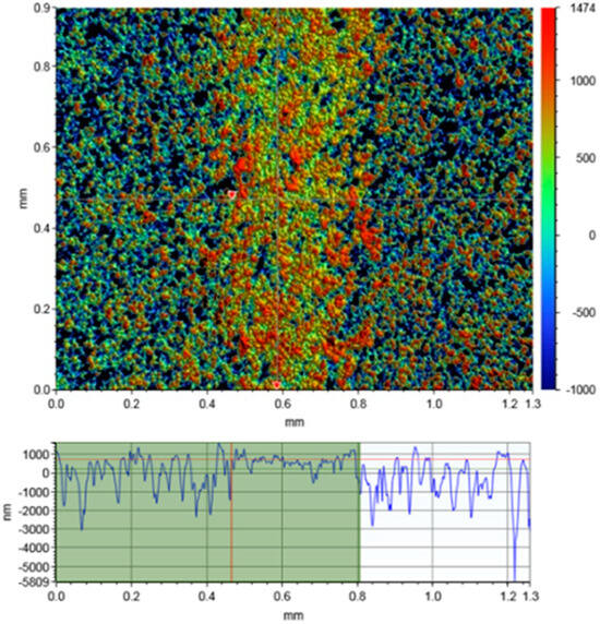
Figure 5.
Confocal interferometry micrograph of PCI tracks with soft wear.
4.2. Electrochemical Test
Table 3 shows the results of the voltage (Ecorr) and corrosion current (Icorr) from the corrosion test performed on the TCI and PDC cutters. Figure 6 shows the potentiodynamic polarization curves resulting from the tests carried out on the PCI and TCI samples. In addition, to compare the curve for a DLC coating with a hardness of 25.3 GPa to improve adhesion, different interlayers were used between the substrate and the DLC [37], which was grown on an AISI H13 tool steel with a hardness of 5 GPa. In this research, passive behavior was not considered, since Human et al. [3] report that the observed behavior qualitatively shows the same characteristics as those exhibited by passivating materials, but the current densities remain high (around 50 µA·cm−2). Therefore, this system cannot be considered truly passivating, where passive currents of around 10 µA·cm−2 are expected; this behavior is called “pseudo-passivity.” This is because, in alkaline solutions, Co shows stable passivity; meanwhile, W readily dissolves the solution observed in acidic electrolytes, and vice versa [38].
Table 3.
Results of corrosion voltages and currents.
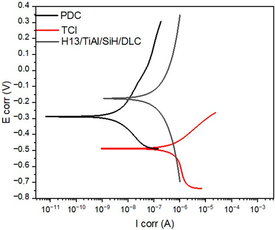
Figure 6.
Potentiodynamic polarization curves: TCI (red) and PDC (black) cutters, and DLC (grey).
As shown in Figure 6 and Table 3, the PDC cutters had a better corrosion behavior than the TCI cutters, having a more positive corrosion potential of −287.8 mV and a lower corrosion current of 3.75 × 10⁻⁹ mA·cm−2. This behavior is a consequence of the difference in the composition and microstructure of the surface, even though both types of drill bits are manufactured via sintering. The corrosion mechanism for this type of composite is proceeded predominantly by the loss of electrons from the binder phase; in this case, it is cobalt. Therefore, it can be expected that as the binder content increases, the corrosion current will increase proportionally. Considering that tungsten carbide inserts have a higher percentage of cobalt than PDC cutters, the corrosion resistance obtained agrees with the results of Human et al. [3]. According to the above results, PDCs have advantages over more conventional cutting tool materials, including sintered tungsten carbide, due to their high hardness, rate wear, and corrosion resistance, which make them a good candidate for the most demanding cutting tool applications. Comparing the results of Figure 6, using DLC coating on a steel substrate for tools results in better behavior than when TCI coatings are used; it could even be a substitute for PDC. Other investigations have also researched corrosion in API X65 steel pipes used in the petrochemical industry [12]; in these, in situ electrochemical measurements were adopted due to the huge challenge of obtaining an electrochemical test device with an excellent sealing performance in high-pressure dynamic environments. However, the FAC under high-CO2 partial-pressure conditions is closely related to the electrochemical process. For this reason, it is also important to carry out electrochemical corrosion tests.
4.3. Selection Material Drill Bits
Figure 7 shows schematically how today’s materials relate to each other in terms of two important characteristics: toughness and hot hardness/abrasion resistance. The ideal cutting tool material would have very high toughness and equally high wear resistance.
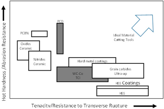
Figure 7.
Material properties for cutting tools.
The main advantage of using PDC cutter bits in rock drilling is that these cutters are designed to cut rock via shearing rather than via crushing or grinding, as is the case with TCI cutters. Rock removal via shearing is more efficient, requiring only 15%–20% of the energy required by crushing and grinding [19]. This, in turn, means that PDC cutters have the potential to drill much faster than conventional cutters; in addition, the abrasion and corrosion resistance results demonstrate that these cutters are the most efficient choice for significantly extending bit life.
5. Conclusions
In this work, it was possible to evaluate the hardness and wear of the drill bits used in the petrochemical industry by using the pin-on-disk test, and it was possible to establish the following:
- The PDC cutters had a higher hardness than the TCI ones. This result was to be expected since the PDC cutters were composed of incrusted diamonds; however, the hardness depended on the amount of Co binder present.
- From the wear test, the results of the coefficient of friction of the TCI were found to be high, considering that its application is as a cutting element; this implies that it consumes more energy for its work.
- The wear mechanisms of the cutters were different. In the TCI cutter, cracks appeared due to the oxidation of the samples. The formation of cracks due to the distribution of friction resulted in the uneven distribution of high local temperatures and in the large temperature gradient of the material. On the other hand, the PDC cutters exhibited soft wear; this type of failure was less important than the other mechanisms present in the PDC inserts, mainly because the hardness of the indenter in the test was lower than that of the cutter.
- Finally, the TCI insert exhibited lower corrosion resistance due to the exchange of electrons with the electrolyte through the cobalt present in the material. Although each insert has a specific application in well drilling, PDC cutters can be applied in more aggressive environments due to their corrosion and wear behavior, but they cost at least five times more than that of inserts. Therefore, it is necessary to look for materials with similar characteristics that are more affordable; one option would be DLC coatings, as the results of the corrosion test showed good corrosion properties.
Author Contributions
Investigation, W.S.H.-C., D.A. and J.J.O.; Writing—review & editing, V.M.C.-Á. All authors have read and agreed to the published version of the manuscript.
Funding
This research received no external funding.
Acknowledgments
We are grateful for the collaboration of the personnel in charge of the metallography, heat treatment, and scanning electron microscopy laboratories of the Universidad Nacional de Colombia for their technical support in the handling of the equipment used for the characterization of the samples. We also appreciate the technical support personnel of the drill bit segment of the Schlumberger company for providing the samples used in this study (TCI and PDC cutters).
Conflicts of Interest
The authors declare no conflict of interest.
References
- Kanyanta, V.; Dormer, A.; Murphy, N.; Invankovic, A. Impact Fatigue Fracture of Polycrystalline Diamond Compact (PDC) Cutters and the Effect of Microstructure. Int. J. Refract. Met. Hard Mater. 2014, 46, 145–151. [Google Scholar] [CrossRef]
- Centala, P.; Challa, V.; Durairajan, B.; Meehan, R.; Páez, L.; Partin, U.; Segal, S.; Wu, S.; Garrett, I.; Teggart, B.; et al. El Diseño de Las Barrenas: Desde Arriba Hasta Abajo. Oilfield Rev. Span. 2003, 23, 4–19. [Google Scholar]
- Human, A.M.; Exner, H.E. Electrochemical Behaviour of Tungsten-Carbide Hardmetals. Mater. Sci. Eng. A 1996, 209, 180–191. [Google Scholar] [CrossRef]
- Zacny, K. Fracture and Fatigue of Polycrystalline-Diamond Compacts. SPE Drill. Complet. 2012, 27, 145–157. [Google Scholar] [CrossRef]
- Moseley, S.G.; Bohn, K.P.; Goedickemeier, M. Core Drilling in Reinforced Concrete Using Polycrystalline Diamond (PCD) Cutters: Wear and Fracture Mechanisms. Int. J. Refract. Met. Hard Mater. 2009, 27, 394–402. [Google Scholar] [CrossRef]
- Lin, T.P.; Cooper, G.A.; Hood, M. Fatigue Test on Polycrystalline Diamond Compacts. Mater. Sci. Eng. A 1993, 163, 23–31. [Google Scholar] [CrossRef]
- Cooley, C.H.; Meany, N.; Hughes, C. The Development of a Fracture-Resistant PDC Cutting Element. In Proceedings of the SPE Annual Technical Conference and Exhibition, New Orleans, LA, USA, 25–28 September 1994; pp. 197–211. [Google Scholar]
- Fang, Z.; Griffo, A.; White, B.; Belnap, D.; Hamilton, R.; Portwood, G.; Cox, P.; Hilmas, G.; Bitler, J. Chipping Resistant Polycrystalline Diamond and Carbide Composite Materials for Roller Cone Bits. In Proceedings of the SPE Annual Technical Conference and Exhibition, New Orleans, LA, USA, 30 September–3 October 2001; pp. 671–678. [Google Scholar] [CrossRef]
- Fang, Z.Z.; Griffo, A.; White, B.; Lockwood, G.; Belnap, D.; Hilmas, G.; Bitler, J. Fracture Resistant Super Hard Materials and Hardmetals Composite with Functionally Designed Microstructure. Int. J. Refract. Met. Hard Mater. 2001, 19, 453–459. [Google Scholar] [CrossRef]
- Rostamsowlat, I.; Evans, B.; Kwon, H.J. A Review of the Frictional Contact in Rock Cutting with a PDC Bit. J. Pet. Sci. Eng. 2022, 208, 109665. [Google Scholar] [CrossRef]
- Abbas, R.K. A Review on the Wear of Oil Drill Bits (Conventional and the State of the Art Approaches for Wear Reduction and Quantification). Eng. Fail. Anal. 2018, 90, 554–584. [Google Scholar] [CrossRef]
- Zeng, L.; Lv, T.; Chen, H.; Ma, T.; Fang, Z.; Shi, J. Flow Accelerated Corrosion of X65 Steel Gradual Contraction Pipe in High CO2 Partial Pressure Environments. Arab. J. Chem. 2023, 16, 104935. [Google Scholar] [CrossRef]
- Dalibon, E.L.; Pecina, J.N.; Cabo, A.; Trava-Airoldi, V.J.; Brühl, S.P. Fretting Wear Resistance of DLC Hard Coatings Deposited on Nitrided Martensitic Stainless Steel. J. Mater. Res. Technol. 2019, 8, 259–266. [Google Scholar] [CrossRef]
- Yao, N.; Evans, A.G.; Cooper, C. V Wear Mechanism Operating in W-DLC Coatings in Contact with Machined Steel Surfaces. Surf. Coat. Technol. 2004, 179, 306–313. [Google Scholar] [CrossRef]
- Suzuki, M.; Saito, T.; Tanaka, A. Tribological Properties of DLC Films against Different Steels. Wear 2013, 304, 83–87. [Google Scholar] [CrossRef]
- Papakonstantinou, P.; Zhao, J.F.; Richardot, A.; McAdams, E.T.; McLaughlin, J.A. Evaluation of Corrosion Performance of Ultra-Thin Si-DLC Overcoats with Electrochemical Impedance Spectroscopy. Diam. Relat. Mater. 2002, 11, 1124–1129. [Google Scholar] [CrossRef]
- Ashby, M.F. Materials Selection in Mechanical Design, 4th ed.; Elsevier: Burlington, NJ, USA, 2013; Volume 53, ISBN 9788578110796. [Google Scholar]
- Field, J.E.; Pickles, C.S. Strength, Fracture and Friction Properties of Diamond. Diam. Relat. Mater. 1996, 5, 625–634. [Google Scholar] [CrossRef]
- Sussmann, R.S. Applications of Diamond Synthesized by Chemical Vapor Deposition. In Handbook of Ceramic Hard Materials; Riedel, R., Ed.; Wiley: Hoboken, NJ, USA, 2008; pp. 573–622. [Google Scholar]
- Islam, M.R.; Hossain, M.E. State-of-the-Art of Drilling. In Drilling Engineering; Gulf Professional Publishing: Woburn, MA, USA, 2021; pp. 17–178. ISBN 9780128201930. [Google Scholar]
- Zhou, Y.; Huang, Z.; Zhang, F.; Jing, S.; Chen, Z.; Ma, Y.; Li, G.; Ren, H. Experimental Study of WC-Co Cemented Carbide Air Impact Rotary Drill Teeth Based on Failure Analysis. Eng. Fail. Anal. 2014, 36, 186–198. [Google Scholar] [CrossRef]
- Kembaiyan, K.T.; Keshavan, K. Combating Severe Fluid Erosion and Corrosion of Drill Bits Using Thermal Spray Coatings. Wear 1995, 186–187, 487–492. [Google Scholar] [CrossRef]
- Yahiaoui, M.; Gerbaud, L.; Paris, J.Y.; Denape, J.; Dourfaye, A. A Study on PDC Drill Bits Quality. Wear 2013, 298–299, 32–41. [Google Scholar] [CrossRef]
- Hincapie, W.S.; Olaya, J.J.; Alfonso, J.E. Propiedades Tribológicas de Recubrimientos de CrxOy Depositados Mediante Proyección Térmica Sobre Latón. Ing. Mecánica Tecnol. Desarro. 2015, 5, 303–311. [Google Scholar]
- Hincapie-campos, W.S.; Jairo, J.; Alfonso-orjuela, J.E. Caracterización Microestructural Mecánica y de Desgaste de Recubrimientos de Cux Aly Depositados Mediante Proyección Térmica. DYNA 2017, 84, 155–163. [Google Scholar] [CrossRef]
- Wojtanowicz, A.K.; Kuru, E. Mathematical Modeling of Pdc Bit Drilling Process Based on a Single-Cutter Mechanics. J. Energy Resour. Technol. Trans. ASME 1993, 115, 247–256. [Google Scholar] [CrossRef]
- Chen, Y.; Wu, J.M.; Nie, X.; Yu, S. Study on Failure Mechanisms of DLC Coated Ti6Al4V and CoCr under Cyclic High Combined Contact Stress. J. Alloys Compd. 2016, 688, 964–973. [Google Scholar] [CrossRef]
- Liu, C.; Bi, Q.; Leyland, A.; Matthews, A. An Electrochemical Impedance Spectroscopy Study of the Corrosion Behaviour of PVD Coated Steels in 0.5 N NaCl Aqueous Solution: Part I. Corros. Sci. 2003, 45, 1257–1273. [Google Scholar] [CrossRef]
- Liu, C.; Bi, Q.; Leyland, A.; Matthews, A. An Electrochemical Impedance Spectroscopy Study of the Corrosion Behaviour of PVD Coated Steels in 0.5 N NaCl Aqueous Solution: Part II. Corros. Sci. 2003, 45, 1243–1256. [Google Scholar] [CrossRef]
- Zhang, K.; Wang, D.; Wang, Z.; Guo, Y. Metals and Hard Materials Material Properties and Tool Performance of PCD Reinforced WC Matrix Composites for Hardbanding Applications. Int. J. Refract. Met. Hard Mater. 2015, 51, 146–152. [Google Scholar] [CrossRef]
- Edrisy, A.; Perry, T.; Cheng, Y.T.; Alpas, A.T. Wear of Thermal Spray Deposited Low Carbon Steel Coatings on Aluminum Alloys. Wear 2001, 251, 1023–1033. [Google Scholar] [CrossRef]
- Bailey, S.G.; Perrott, C.M. Wear Processes Exhibited by WC-Co Rotary Cutters in Mining. Wear 1974, 29, 117–128. [Google Scholar] [CrossRef]
- Llanes, L.; Torres, Y.; Anglada, M. On the Fatigue Crack Growth Behavior of WC-Co Cemented Carbides: Kinetics Description, Microstructural Effects and Fatigue Sensitivity. Acta Mater. 2002, 50, 2381–2393. [Google Scholar] [CrossRef]
- Gee, M.G.; Gant, A.; Roebuck, B. Wear Mechanisms in Abrasion and Erosion of WC/Co and Related Hardmetals. Wear 2007, 263, 137–148. [Google Scholar] [CrossRef]
- Konyashin, I.; Ries, B. Wear Damage of Cemented Carbides with Different Combinations of WC Mean Grain Size and Co Content. Part I: ASTM Wear Tests. Int. J. Refract. Met. Hard Mater. 2014, 46, 12–19. [Google Scholar] [CrossRef]
- Lin, T.-P.; Hood, M.; Cooper, G.A.; Li, X. Wear and Failure Mechanisms of Polycystalline Diamond Compact Bits. Wear 1992, 156, 133–150. [Google Scholar]
- Hincapie C., W.S.; Gutiérrez B., J.M.; Trava-airoldi, V.J.; Olaya F., J.J.; Alfonso, J.E.; Capote, G. Influence of the TixSi and TixSi/a-Si: H Interlayers on Adherence of Diamond-like Carbon Coatings. Diam. Relat. Mater. 2020, 109, 108079. [Google Scholar] [CrossRef]
- Kellner, F.J.J.; Hildebrand, H.; Virtanen, S. Effect of WC Grain Size on the Corrosion Behavior of WC-Co Based Hardmetals in Alkaline Solutions. Int. J. Refract. Met. Hard Mater. 2009, 27, 806–812. [Google Scholar] [CrossRef]
Disclaimer/Publisher’s Note: The statements, opinions and data contained in all publications are solely those of the individual author(s) and contributor(s) and not of MDPI and/or the editor(s). MDPI and/or the editor(s) disclaim responsibility for any injury to people or property resulting from any ideas, methods, instructions or products referred to in the content. |
© 2023 by the authors. Licensee MDPI, Basel, Switzerland. This article is an open access article distributed under the terms and conditions of the Creative Commons Attribution (CC BY) license (https://creativecommons.org/licenses/by/4.0/).