
Carbonation Resistance of Surface Protective Materials Modified with Hybrid NanoSiO2

Abstract
1. Introduction
2. Materials and Methods
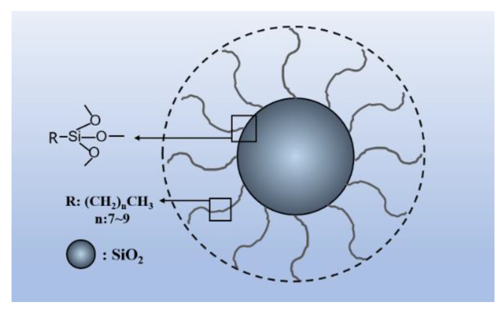
2.1. Materials
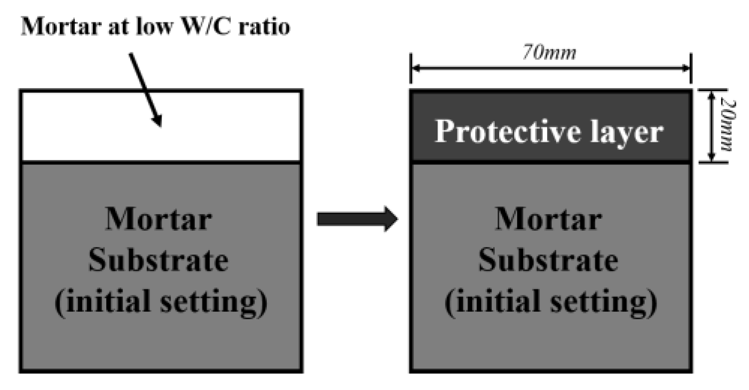
2.2. Sample Preparation
2.3. Test Methods
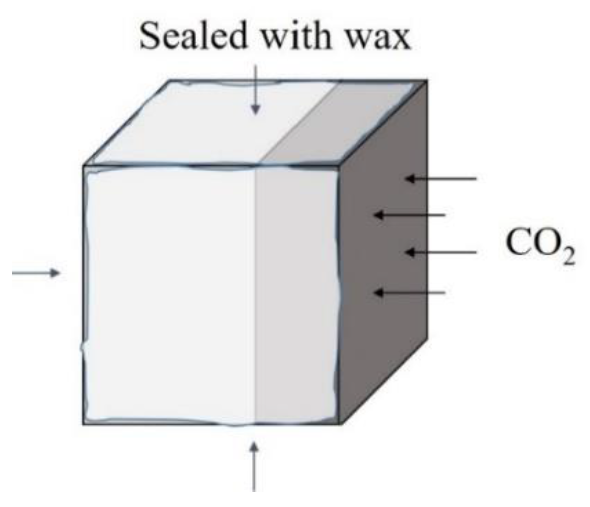
2.3.1. Carbonation Depth
2.3.2. Chemical Composition
2.3.3. Pore Structures
2.3.4. Thermodynamic Modeling
3. Results and Discussion
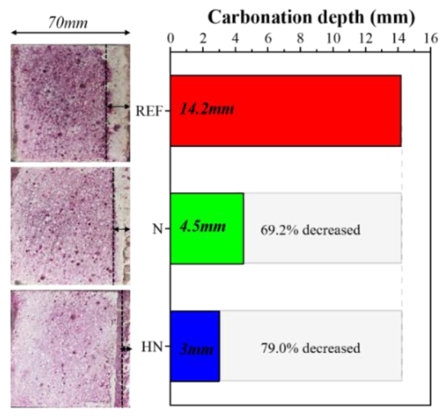
3.1. Carbonation Depth
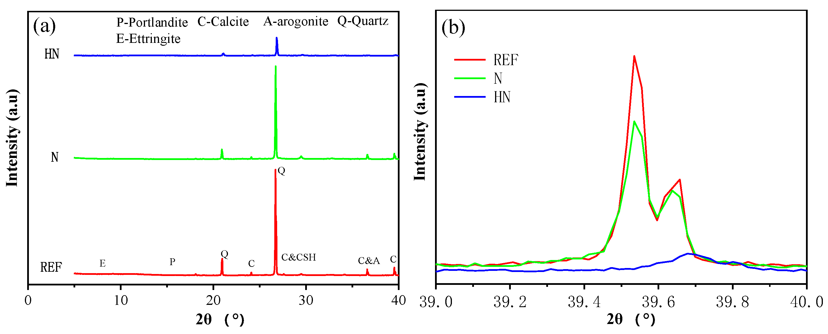
3.2. XRD
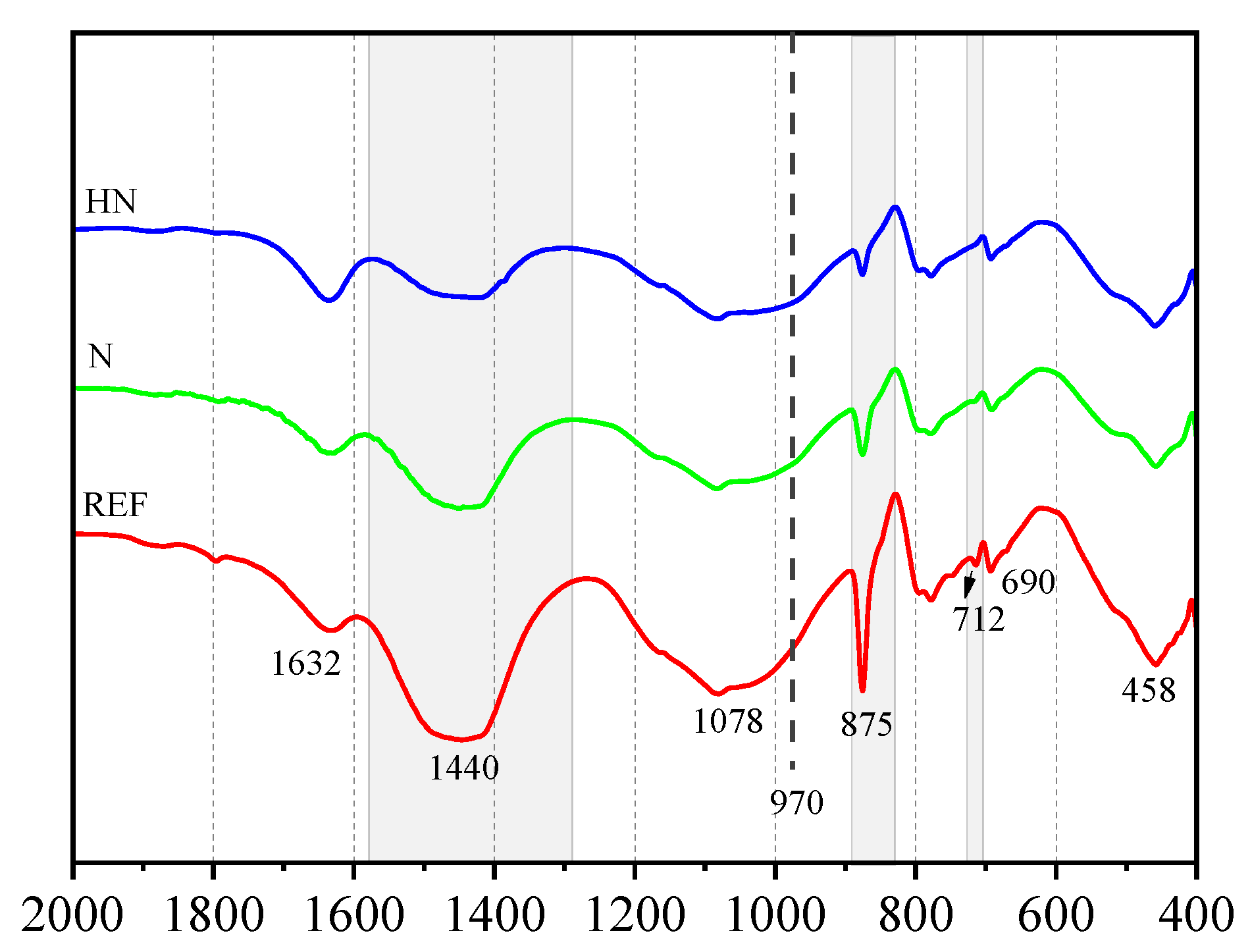
3.3. FTIR
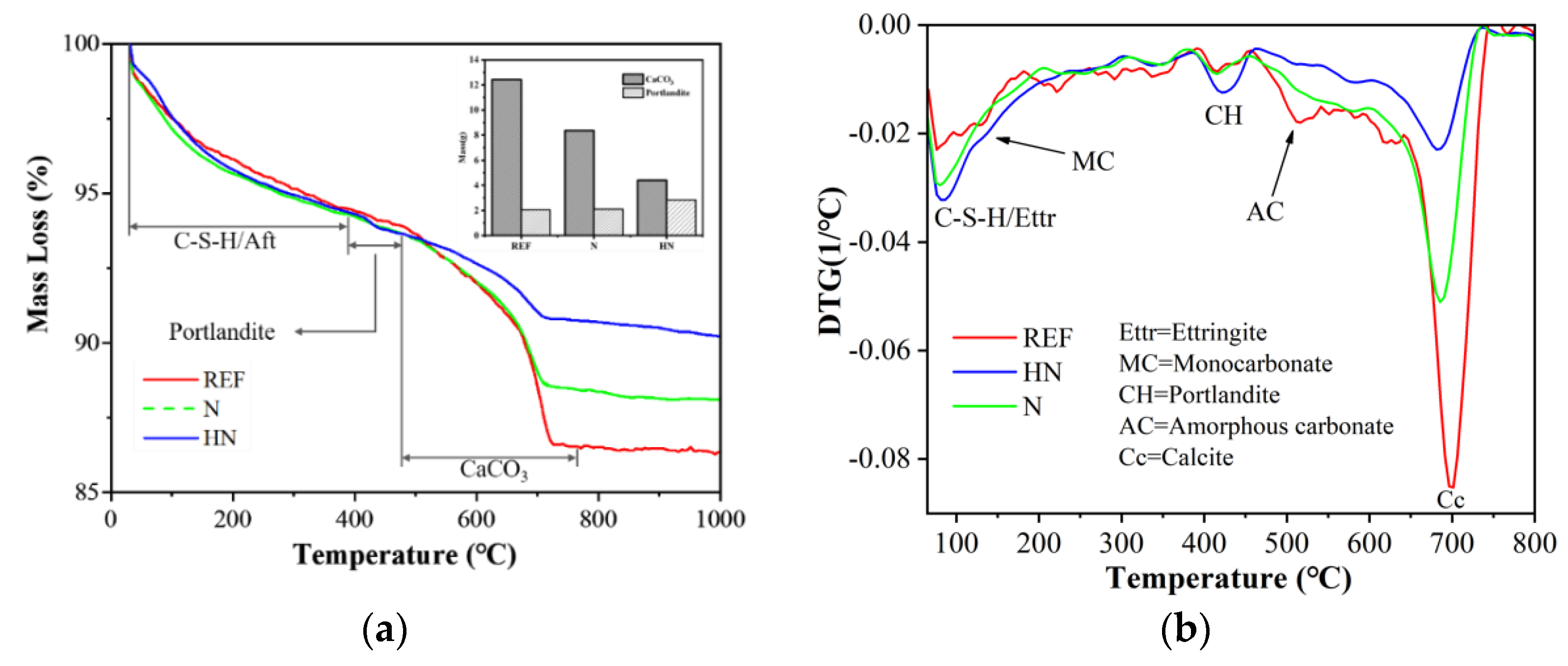
3.4. TG
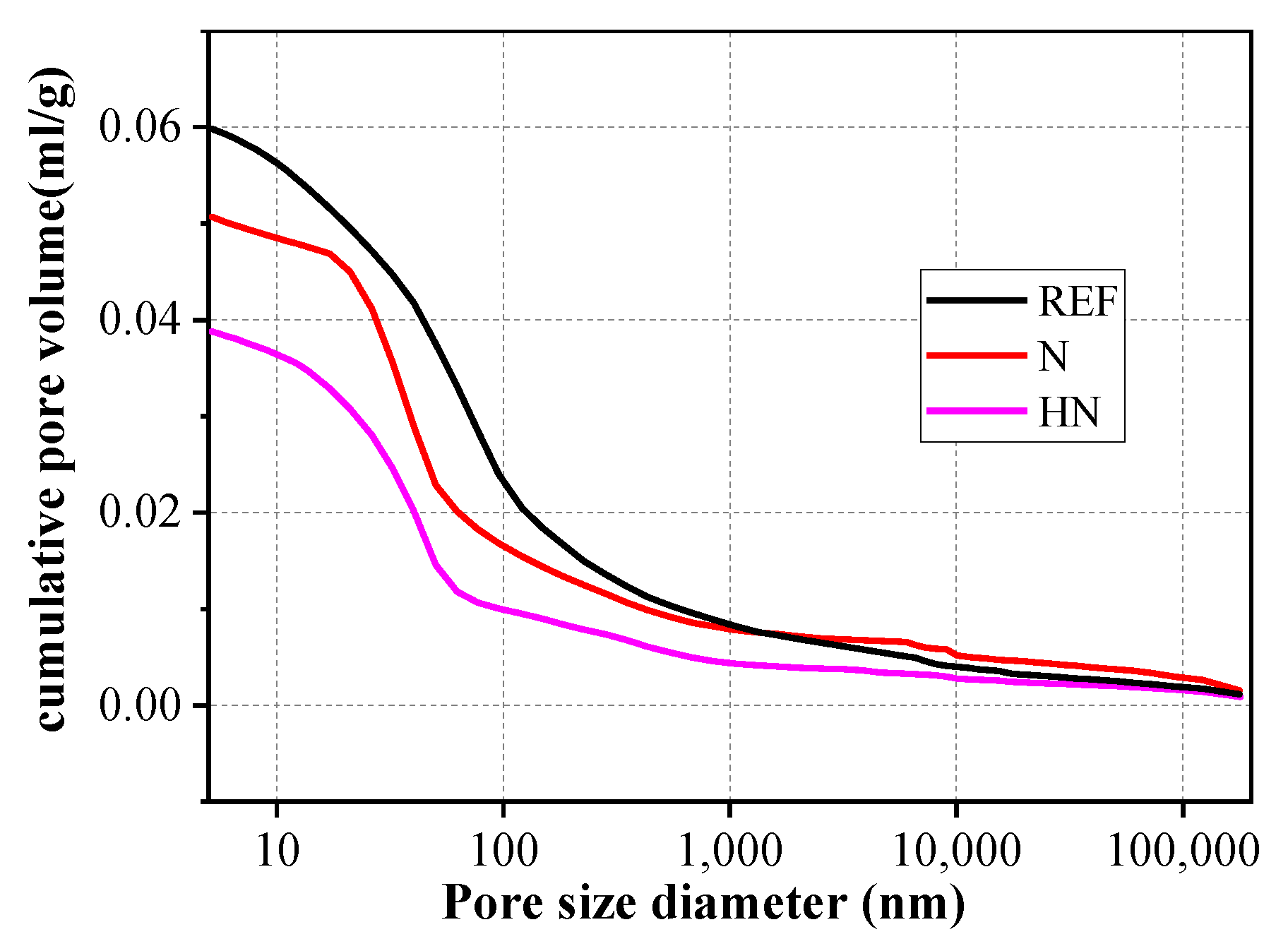
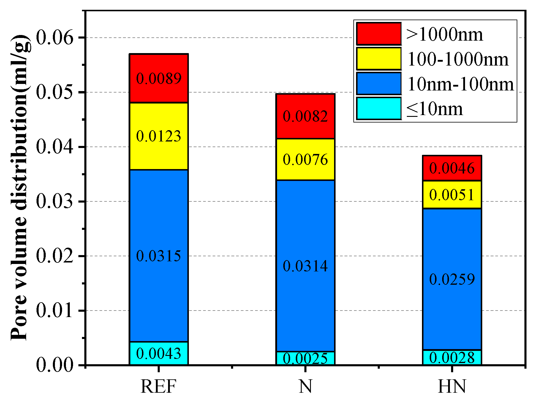
3.5. Pore Structures
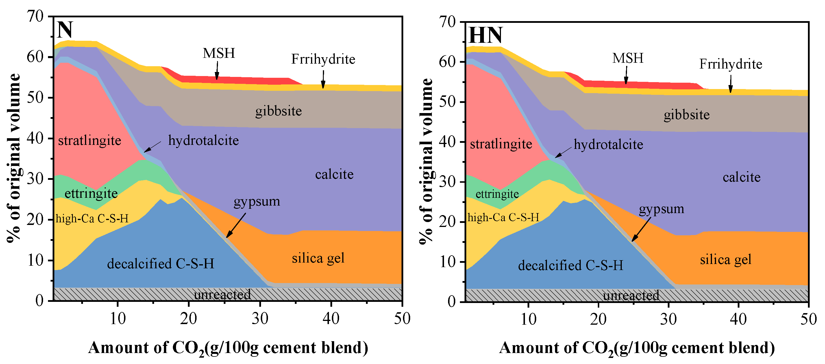
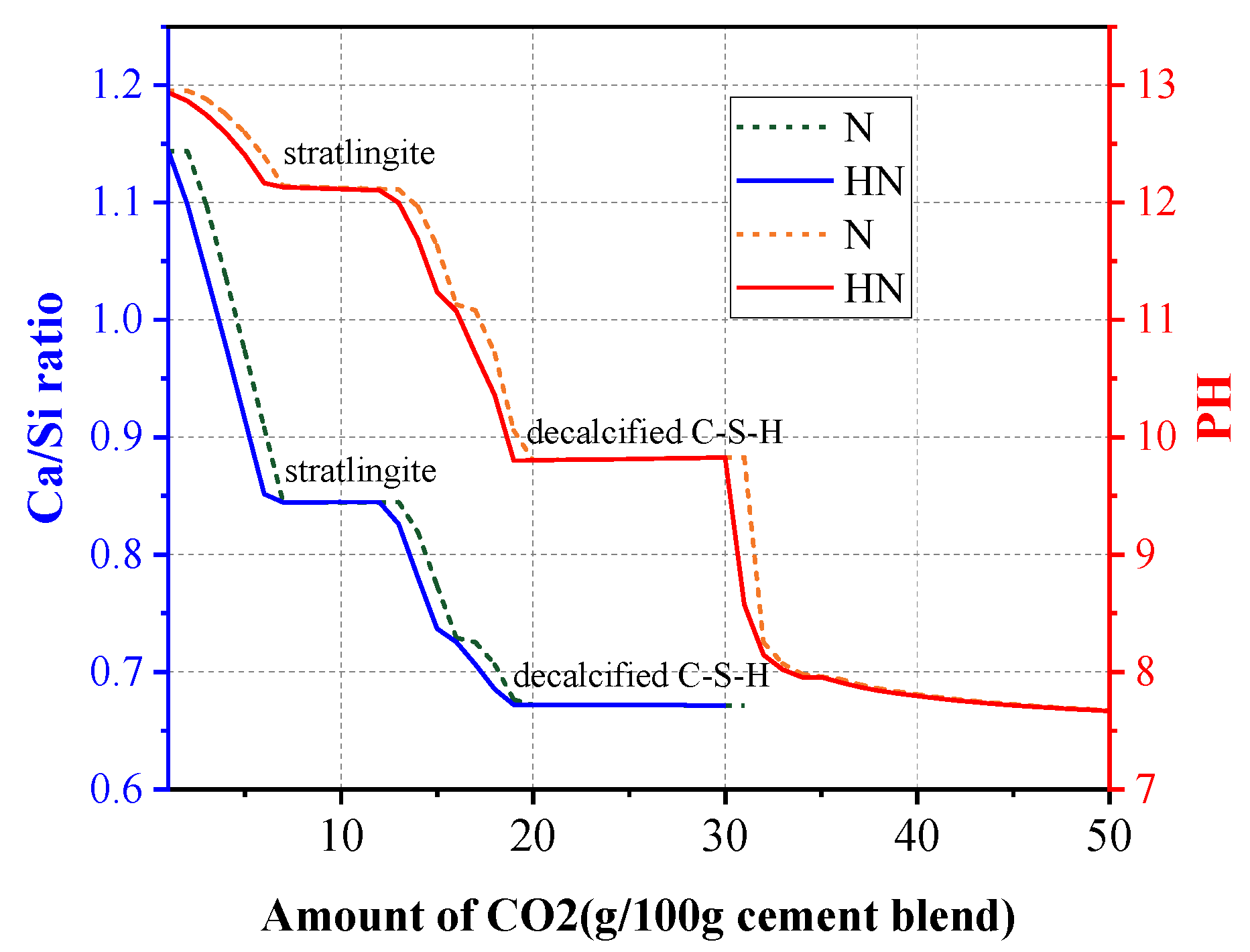
3.6. Thermodynamic Modeling
4. Conclusions
- The use of SPMs effectively increased the carbonation resistance of the substrates. Compared with REF, the carbonation depth of N and HN was reduced by 69.2% and 79.0%, respectively.
- The combination of HNS with SPMs further enhanced the carbonation resistance. Compared with the SPMs without HNS, the carbonation depth of the HNS incorporated SPMs was reduced from 4.5 to 3 mm.
- The incorporation of HNS in SPMs refined the pore structures. Compared with the SPMs without HNS, the HNS incorporated SPMs experienced a 43.9% and 32.9% reduction in big pores and capillary pores, respectively. This was ascribed to the formation of extra C–S–H and the filling effect of nanoparticles.
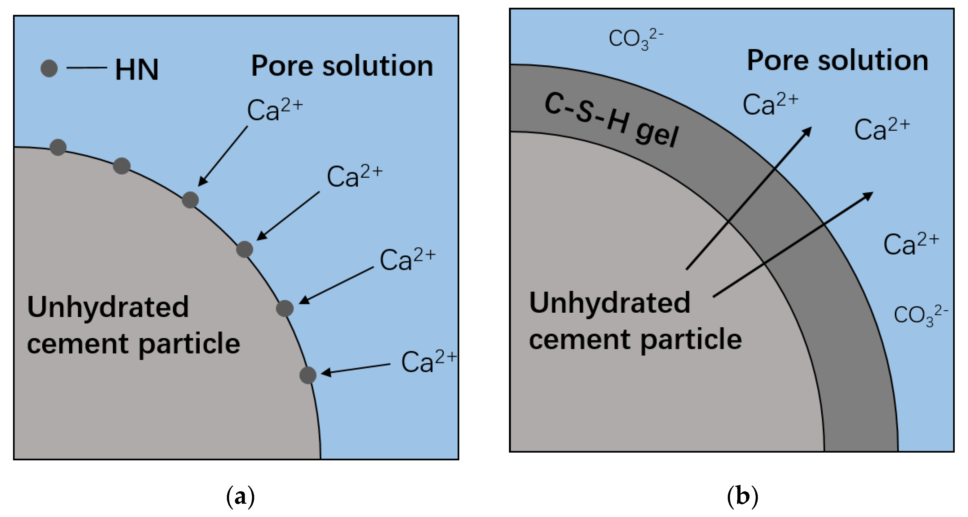
- From thermodynamic modeling, it can be observed that the introduction of HNS could promote the formation of C–S–(A)–H, prevent the decrease of pH in pore solution, and lower the Ca/Si ratio of C–S–(A)–H. These effects are beneficial to augmenting the carbonation resistance of SPMs.
Author Contributions
Funding
Data Availability Statement
Acknowledgments
Conflicts of Interest
References
- Zhan, B.; Poon, C.; Shi, C. CO2 curing for improving the properties of concrete blocks containing recycled aggregates. Cem. Concr. Compos. 2013, 42, 1–8. [Google Scholar] [CrossRef]
- Thomas, J.J.; Biernacki, J.J.; Bullard, J.W.; Bishnoi, S.; Dolado, J.S.; Scherer, G.W.; Luttge, A. Modeling and simulation of cement hydration kinetics and microstructure development. Cem. Concr. Res. 2011, 41, 1257–1278. [Google Scholar] [CrossRef]
- Xi, F.; Davis, S.J.; Ciais, P.; Crawford-Brown, D.; Guan, D.; Pade, C.; Shi, T.; Syddall, M.; Lv, J.; Ji, L.; et al. Substantial global carbon uptake by cement carbonation. Nat. Geosci. 2016, 9, 880–883. [Google Scholar] [CrossRef]
- Andres, R.J.; Boden, T.A.; Bréon, F.M.; Ciais, P.; Davis, S.; Erickson, D.; Gregg, J.S.; Jacobson, A.; Marland, G.; Miller, J.; et al. A synthesis of carbon dioxide emissions from fossil-fuel combustion. Biogeosciences 2015, 9, 1845–1871. [Google Scholar] [CrossRef]
- Richardson, M.G. Fundamentals of Durable Reinforced Concrete; Spon Press: New York, NY, USA, 2002. [Google Scholar]
- Shah, V.; Scrivener, K.; Bhattacharjee, B.; Bishnoi, S. Changes in microstructure characteristics of cement paste on carbonation. Cem. Concr. Res. 2018, 109, 184–197. [Google Scholar] [CrossRef]
- Seneviratne, A.M.G.; Sergi, G.; Page, C.L. Performance characteristics of surface coatings applied to concrete for control of reinforcement corrosion. Constr. Build. Mater. 2000, 14, 55–59. [Google Scholar] [CrossRef]
- Ibrahim, M. Effectiveness of concrete surface treatment materials in reducing chloride-induced reinforcement corrosion. Constr. Build. Mater. 1997, 11, 443–451. [Google Scholar] [CrossRef]
- Papadakis, V.G. Effect of supplementary cementing materials on concrete resistance against carbonation and chloride ingress. Cem. Concr. Res. 2000, 30, 291–299. [Google Scholar] [CrossRef]
- Xue, L.; Zhang, Z.; Wang, H. Hydration mechanisms and durability of hybrid alkaline cements (HACs): A review. Constr. Build. Mater. 2021, 266, 121039. [Google Scholar] [CrossRef]
- Parron-Rubio, M.E.; Perez-Garcia, F.; Gonzalez-Herrera, A.; Oliveira, M.J.; Rubio-Cintas, M.D. Slag substitution as a cementing material in concrete: Mechanical, physical and environmental properties. Materials 2019, 12, 2845. [Google Scholar] [CrossRef]
- Lam, L.; Wong, Y.L.; Poon, C.S. Degree of hydration and gel/space ratio of high-volume fly ash/cement systems. Constr. Build. Mater. 2000, 30, 747–756. [Google Scholar] [CrossRef]
- Yehdego, T.; Peethamparan, S. The role of nano silica in modifying the early age hydration kinetics of binders containing high volume fly ashes. In Nanotechnology in Construction; Springer International Publishing: Cham, Switzerland, 2015; pp. 399–405. [Google Scholar]
- Gu, Y.; Ran, Q.; She, W.; Liu, J. Modifying Cement Hydration with NS@PCE Core-Shell Nanoparticles. Adv. Mater. Sci. Eng. 2017, 2017, 1–13. [Google Scholar] [CrossRef]
- Shah, S.P.; Hou, P.; Konsta-Gdoutos, M.S. Nano-modification of cementitious material: Toward a stronger and durable concrete. J. Sustain. Cem. Based Mater. 2016, 5, 1–22. [Google Scholar] [CrossRef]
- Du, H.; Du, S.; Liu, X. Durability performances of concrete with nano-silica. Constr. Build. Mater. 2014, 73, 705–712. [Google Scholar] [CrossRef]
- Thomas, J.J.; Jennings, H.M.; Chen, J.J. Influence of nucleation seeding on the hydration mechanisms of tricalcium silicate and cement. J. Phys. Chem. C 2009, 113, 4327–4334. [Google Scholar] [CrossRef]
- Sandrolini, F.; Franzoni, E.; Pigino, B. Ethyl silicate for surface treatment of concrete–Part I: Pozzolanic effect of ethyl silicate. Cem. Concr. Compos. 2012, 34, 306–312. [Google Scholar] [CrossRef]
- Hou, P.; Qian, J.; Cheng, X.; Shah, S.P. Effects of the pozzolanic reactivity of nanoSiO2 on cement-based materials. Cem. Concr. Compos. 2015, 55, 250–258. [Google Scholar] [CrossRef]
- Hou, P.; Cheng, X.; Qian, J.; Zhang, R.; Cao, W.; Shah, S.P. Characteristics of surface-treatment of nano-SiO2 on the transport properties of hardened cement pastes with different water-to-cement ratios. Cem. Concr. Compos. 2015, 55, 26–33. [Google Scholar] [CrossRef]
- Ghafari, E.; Costa, H.; Júlio, E.; Portugal, A.; Durães, L. The effect of nanosilica addition on flowability, strength and transport properties of ultra high performance concrete. Mater. Eng. 2014, 59, 1–9. [Google Scholar] [CrossRef]
- Gu, Y.; Ran, Q.; Shu, X.; Yu, C.; Chang, H.; Liu, J. Synthesis of nanoSiO2@PCE core-shell nanoparticles and its effect on cement hydration at early age. Constr. Build. Mater. 2016, 114, 673–680. [Google Scholar] [CrossRef]
- Collodetti, G.; Gleize, P.J.P.; Monteiro, P.J.M. Exploring the potential of siloxane surface modified nano-SiO2 to improve the Portland cement pastes hydration properties. Constr. Build. Mater. 2014, 54, 99–105. [Google Scholar] [CrossRef]
- Mora, E.; González, G.; Romero, P.; Castellón, E. Control of water absorption in concrete materials by modification with hybrid hydrophobic silica particles. Constr. Build. Mater. 2019, 221, 210–218. [Google Scholar] [CrossRef]
- Lothenbach, B.; Kulik, D.A.; Matschei, T.; Balonis, M.; Baquerizo, L.; Dilnesa, B.; Miron, G.D.; Myers, R.J. Cemdata18: A chemical thermodynamic database for hydrated Portland cements and alkali-activated materials. Cem. Concr. Res. 2019, 115, 472–506. [Google Scholar] [CrossRef]
- Siddique, S.; Naqi, A.; Jang, J.G. Influence of water to cement ratio on CO2 uptake capacity of belite-rich cement upon exposure to carbonation curing. Cem. Concr. Compos. 2020, 111, 103616. [Google Scholar] [CrossRef]
- Pan, X.; Shi, C.; Farzadnia, N.; Hu, X.; Zheng, J. Properties and microstructure of CO2 surface treated cement mortars with subsequent lime-saturated water curing. Cem. Concr. Compos. 2019, 99, 89–99. [Google Scholar] [CrossRef]
- Chen, T.; Gao, X. Effect of carbonation curing regime on strength and microstructure of Portland cement paste. J. CO2 Utilization 2019, 34, 74–86. [Google Scholar] [CrossRef]
- Šauman, Z. Carbonization of porous concrete and its main binding components. Cem. Concr. Res. 1971, 1, 645–662. [Google Scholar] [CrossRef]
- Rostami, V.; Shao, Y.; Boyd, A.J.; He, Z. Microstructure of cement paste subject to early carbonation curing. Cem. Concr. Res. 2012, 42, 186–193. [Google Scholar] [CrossRef]
- Shi, Z.; Lothenbach, B.; Geiker, M.R.; Kaufmann, J.; Leemann, A.; Ferreiro, S.; Skibsted, J. Experimental studies and thermodynamic modeling of the carbonation of Portland cement, metakaolin and limestone mortars. Cem. Concr. Res. 2016, 88, 60–72. [Google Scholar] [CrossRef]
- Li, R.; Hou, P.; Xie, N.; Ye, Z.; Cheng, X.; Shah, S.P. Design of SiO2/PMHS hybrid nanocomposite for surface treatment of cement-based materials. Cem. Concr. Compos. 2018, 87, 89–97. [Google Scholar] [CrossRef]
- Powers, T.C. Structure and physical properties of hardened portland cement paste. J. Am. Ceram. Soc. 1958, 41, 1–6. [Google Scholar] [CrossRef]
- Jennings, H.M.; Kumar, A.; Sant, G. Quantitative discrimination of the nano-pore-structure of cement paste during drying: New insights from water sorption isotherms. Cem. Concr. Res. 2015, 76, 27–36. [Google Scholar] [CrossRef]
- Wang, Q.; Li, S.; Pan, S.; Cui, X.; Corr, D.J.; Shah, S.P. Effect of graphene oxide on the hydration and microstructure of fly ash-cement system. Constr. Build. Mater. 2019, 198, 106–119. [Google Scholar] [CrossRef]


| Component | CaO | SiO2 | Al2O3 | Fe2O3 | SO3 | MgO | K2O | L.O.I. |
|---|---|---|---|---|---|---|---|---|
| Content(wt%) | 62.83 | 20.50 | 5.61 | 3.84 | 3.07 | 1.70 | 1.31 | 1.14 |
| Component | CaO | SiO2 | Al2O3 | Fe2O3 | SO3 | MgO | K2O | L.O.I. |
|---|---|---|---|---|---|---|---|---|
| Content(wt%) | 3.39 | 57.23 | 28.34 | 4.07 | 1.08 | 1.22 | 2.51 | 1.02 |
| Component | CaO | SiO2 | Al2O3 | Fe2O3 | SO3 | MgO | K2O | L.O.I. |
|---|---|---|---|---|---|---|---|---|
| Content(wt%) | 26.51 | 46.29 | 7.84 | 5.05 | 0.62 | 10.46 | 1.76 | 1.47 |
| Parts | Water/Binder | Sand/Binder | FA(wt%) | Slag(wt%) | HNS(wt%) |
|---|---|---|---|---|---|
| SPM-0 | 0.40 | 3:1 | 15 | 15 | 0 |
| SPM-1 | 0.40 | 3:1 | 15 | 15 | 1 |
| Substrates | 0.53 | 3:1 | 15 | 15 | 0 |
| Abbreviations | Content of Reference |
|---|---|
| SPMs | Srface protect materials |
| SCMs | Supplementary cementitious materials |
| NS | NanoSiO2 |
| HNS | Hybrid nanoSiO2 |
| FA | Fly ash |
| CH | Ca(OH)2 |
| XRD | X-ray diffraction |
| TGA | Thermal gravimetric analysis |
| FTIR | Fourier-transform infrared spectroscopy |
| MIP | Mercury intrusion porosimeter |
| REF | Samples consist of substrates without SPM |
| N | Samples consist of substrates and SPM-0 |
| HN | Samples consist of substrates and SPM-1 |
| Components | REF | N | HN |
|---|---|---|---|
| CaCO3(wt%) | 12.42 | 8.37 | 4.40 |
| Ca(OH)2(wt%) | 2.05 | 2.11 | 2.85 |
Publisher’s Note: MDPI stays neutral with regard to jurisdictional claims in published maps and institutional affiliations. |
© 2021 by the authors. Licensee MDPI, Basel, Switzerland. This article is an open access article distributed under the terms and conditions of the Creative Commons Attribution (CC BY) license (http://creativecommons.org/licenses/by/4.0/).
Share and Cite
Xia, K.; Gu, Y.; Jiang, L.; Guo, M.; Chen, L.; Hu, F. Carbonation Resistance of Surface Protective Materials Modified with Hybrid NanoSiO2. Coatings 2021, 11, 269. https://doi.org/10.3390/coatings11030269
Xia K, Gu Y, Jiang L, Guo M, Chen L, Hu F. Carbonation Resistance of Surface Protective Materials Modified with Hybrid NanoSiO2. Coatings. 2021; 11(3):269. https://doi.org/10.3390/coatings11030269
Chicago/Turabian StyleXia, Kailun, Yue Gu, Linhua Jiang, Mingzhi Guo, Lei Chen, and Feilong Hu. 2021. "Carbonation Resistance of Surface Protective Materials Modified with Hybrid NanoSiO2" Coatings 11, no. 3: 269. https://doi.org/10.3390/coatings11030269
APA StyleXia, K., Gu, Y., Jiang, L., Guo, M., Chen, L., & Hu, F. (2021). Carbonation Resistance of Surface Protective Materials Modified with Hybrid NanoSiO2. Coatings, 11(3), 269. https://doi.org/10.3390/coatings11030269