
Hole-Transport Material Engineering in Highly Durable Carbon-Based Perovskite Photovoltaic Devices


Abstract
1. Introduction
2. Materials and Methods
2.1. Preparation of TiO2 Compact and Mesoporous Layers
2.2. Perovskite Precursor Solution and Deposition
2.3. PMMA Precursor Solution
2.4. Hole-Transporting Layers
2.5. Back Contact
2.6. Device Characterization
3. Results and Discussion
4. Conclusions
Author Contributions
Funding
Data Availability Statement
Acknowledgments
Conflicts of Interest
References
- NREL. Best Research-Cell Efficiency Chart. Photovoltaic Research; NREL: Golden, CO, USA, 2022. [Google Scholar]
- Mehrabian, M.; Afshar, E.N.; Akhavan, O. TiO2 and C60 Transport Nanolayers in Optimized Pb-Free CH3NH3SnI3-Based Perovskite Solar Cells. Mater. Sci. Eng. B 2023, 287, 116146. [Google Scholar] [CrossRef]
- Pellet, N.; Gao, P.; Gregori, G.; Yang, T.-Y.; Nazeeruddin, M.K.; Maier, J.; Grätzel, M. Mixed-Organic-Cation Perovskite Photovoltaics for Enhanced Solar-Light Harvesting. Angew. Chem. Int. Ed. 2014, 53, 3151–3157. [Google Scholar] [CrossRef] [PubMed]
- Yang, W.S.; Noh, J.H.; Jeon, N.J.; Kim, Y.C.; Ryu, S.; Seo, J.; Seok, S.I. SOLAR CELLS. High-Performance Photovoltaic Perovskite Layers Fabricated through Intramolecular Exchange. Science 2015, 348, 1234–1237. [Google Scholar] [CrossRef] [PubMed]
- Ogomi, Y.; Morita, A.; Tsukamoto, S.; Saitho, T.; Fujikawa, N.; Shen, Q.; Toyoda, T.; Yoshino, K.; Pandey, S.S.; Ma, T.; et al. CH3NH3SnxPb(1–x)I3 Perovskite Solar Cells Covering up to 1060 nm. J. Phys. Chem. Lett. 2014, 5, 1004–1011. [Google Scholar] [CrossRef] [PubMed]
- Stoumpos, C.C.; Malliakas, C.D.; Kanatzidis, M.G. Semiconducting Tin and Lead Iodide Perovskites with Organic Cations: Phase Transitions, High Mobilities, and Near-Infrared Photoluminescent Properties. Inorg. Chem. 2013, 52, 9019–9038. [Google Scholar] [CrossRef]
- Noh, J.H.; Im, S.H.; Heo, J.H.; Mandal, T.N.; Seok, S.I. Chemical Management for Colorful, Efficient, and Stable Inorganic–Organic Hybrid Nanostructured Solar Cells. Nano Lett. 2013, 13, 1764–1769. [Google Scholar] [CrossRef]
- Holzhey, P.; Saliba, M. A Full Overview of International Standards Assessing the Long-Term Stability of Perovskite Solar Cells. J. Mater. Chem. A 2018, 6, 21794–21808. [Google Scholar] [CrossRef]
- Wang, F.; Ge, C.Y.; Duan, D.; Lin, H.; Li, L.; Naumov, P.; Hu, H. Recent Progress in Ionic Liquids for Stability Engineering of Perovskite Solar Cells. Small Struct. 2022, 3, 2200048. [Google Scholar] [CrossRef]
- Shooshtari, L.; Esfandiar, A.; Orooji, Y.; Samadpour, M.; Rahighi, R. Ultrafast and Stable Planar Photodetector Based on SnS2 Nanosheets/Perovskite Structure. Sci. Rep. 2021, 11, 19353. [Google Scholar] [CrossRef]
- Park, J.; Kim, J.; Yun, H.-S.; Paik, M.J.; Noh, E.; Mun, H.J.; Kim, M.G.; Shin, T.J.; Seok, S.I. Controlled Growth of Perovskite Layers with Volatile Alkylammonium Chlorides. Nature 2023, 1–3. [Google Scholar] [CrossRef]
- De Wolf, S.; Holovsky, J.; Moon, S.-J.; Löper, P.; Niesen, B.; Ledinsky, M.; Haug, F.-J.; Yum, J.-H.; Ballif, C. Organometallic Halide Perovskites: Sharp Optical Absorption Edge and Its Relation to Photovoltaic Performance. J. Phys. Chem. Lett. 2014, 5, 1035–1039. [Google Scholar] [CrossRef] [PubMed]
- Biewald, A.; Giesbrecht, N.; Bein, T.; Docampo, P.; Hartschuh, A.; Ciesielski, R. Temperature-Dependent Ambipolar Charge Carrier Mobility in Large-Crystal Hybrid Halide Perovskite Thin Films. ACS Appl. Mater. Interfaces 2019, 11, 20838–20844. [Google Scholar] [CrossRef] [PubMed]
- Galkowski, K.; Mitioglu, A.; Miyata, A.; Plochocka, P.; Portugall, O.; Eperon, G.E.; Wang, J.T.-W.; Stergiopoulos, T.; Stranks, S.D.; Snaith, H.J.; et al. Determination of the Exciton Binding Energy and Effective Masses for Methylammonium and Formamidinium Lead Tri-Halide Perovskite Semiconductors. Energy Environ. Sci. 2016, 9, 962–970. [Google Scholar] [CrossRef]
- Tainter, G.D.; Hörantner, M.T.; Pazos-Outón, L.M.; Lamboll, R.D.; Āboliņš, H.; Leijtens, T.; Mahesh, S.; Friend, R.H.; Snaith, H.J.; Joyce, H.J.; et al. Long-Range Charge Extraction in Back-Contact Perovskite Architectures via Suppressed Recombination. Joule 2019, 3, 1301–1313. [Google Scholar] [CrossRef]
- Zhang, X.; Turiansky, M.E.; Shen, J.-X.; Van de Walle, C.G. Defect Tolerance in Halide Perovskites: A First-Principles Perspective. J. Appl. Phys. 2022, 131, 090901. [Google Scholar] [CrossRef]
- Domanski, K.; Correa-Baena, J.-P.; Mine, N.; Nazeeruddin, M.K.; Abate, A.; Saliba, M.; Tress, W.; Hagfeldt, A.; Grätzel, M. Not All That Glitters Is Gold: Metal-Migration-Induced Degradation in Perovskite Solar Cells. ACS Nano 2016, 10, 6306–6314. [Google Scholar] [CrossRef]
- Hoque, M.N.F.; Islam, N.; Zhu, K.; Fan, Z. Hybrid Perovskite Phase Transition and Its Ionic, Electrical and Optical Properties. MRS Adv. 2017, 2, 3077–3082. [Google Scholar] [CrossRef]
- Leonard, A.A.; Diroll, B.T.; Flanders, N.C.; Panuganti, S.; Brumberg, A.; Kirschner, M.S.; Cuthriell, S.A.; Harvey, S.M.; Watkins, N.E.; Yu, J.; et al. Light-Induced Transient Lattice Dynamics and Metastable Phase Transition in CH3NH3PbI3 Nanocrystals. ACS Nano 2023. [Google Scholar] [CrossRef]
- Macpherson, S.; Doherty, T.A.S.; Winchester, A.J.; Kosar, S.; Johnstone, D.N.; Chiang, Y.-H.; Galkowski, K.; Anaya, M.; Frohna, K.; Iqbal, A.N.; et al. Local Nanoscale Phase Impurities Are Degradation Sites in Halide Perovskites. Nature 2022, 607, 294–300. [Google Scholar] [CrossRef]
- Hatamvand, M.; Gholipour, S.; Chen, M.; Zhou, Y.; Jiang, T.; Hu, Z.; Chen, Y.; Huang, W. Dual-Side Interfacial Passivation of FAPbI3 Perovskite Film by Naphthylmethylammonium Iodide for Highly Efficient and Stable Perovskite Solar Cells. Chem. Eng. J. 2023, 460, 141788. [Google Scholar] [CrossRef]
- Turren-Cruz, S.-H.; Hagfeldt, A.; Saliba, M. Methylammonium-Free, High-Performance and Stable Perovskite Solar Cells on a Planar Architecture. Science 2018, 362, eaat3583. [Google Scholar] [CrossRef] [PubMed]
- Matsui, T.; Yamamoto, T.; Nishihara, T.; Morisawa, R.; Yokoyama, T.; Sekiguchi, T.; Negami, T. Compositional Engineering for Thermally Stable, Highly Efficient Perovskite Solar Cells Exceeding 20% Power Conversion Efficiency with 85 °C/85% 1000 h Stability. Adv. Mater. 2019, 31, 1806823. [Google Scholar] [CrossRef] [PubMed]
- Mahmoudian, L.; Rashidi, A.; Dehghani, H.; Rahighi, R. Single-Step Scalable Synthesis of Three-Dimensional Highly Porous Graphene with Favorable Methane Adsorption. Chem. Eng. J. 2016, 304, 784–792. [Google Scholar] [CrossRef]
- Rahighi, R.; Akhavan, O.; Zeraati, A.S.; Sattari-Esfahlan, S.M. All-Carbon Negative Differential Resistance Nanodevice Using a Single Flake of Nanoporous Graphene. ACS Appl. Electron. Mater. 2021, 3, 3418–3427. [Google Scholar] [CrossRef]
- Pourfarzad, H.; Olia, M.H.; Shirojan, A.; Ganjali, M.R.; Rahighi, R. Effects of Sintering Temperature and Press Pressure on the Microstructure and Electrochemical Behaviour of the Ag2O/GO Nanocomposite. Russ. J. Electrochem. 2018, 54, 1053–1066. [Google Scholar] [CrossRef]
- Jalilinejad, N.; Rabiee, M.; Baheiraei, N.; Ghahremanzadeh, R.; Salarian, R.; Rabiee, N.; Akhavan, O.; Zarrintaj, P.; Hejna, A.; Saeb, M.R.; et al. Electrically Conductive Carbon-Based (Bio)-Nanomaterials for Cardiac Tissue Engineering. Bioeng. Transl. Med. 2003, 8, e10347. [Google Scholar] [CrossRef]
- Feizi, S.; Malekie, S.; Rahighi, R.; Tayyebi, A.; Ziaie, F. Evaluation of Dosimetric Characteristics of Graphene Oxide/PVC Nanocomposite for Gamma Radiation Applications. Radiochim. Acta 2017, 105, 161–170. [Google Scholar] [CrossRef]
- Zhang, H.; Li, Y.; Tan, S.; Chen, Z.; Song, K.; Huang, S.; Shi, J.; Luo, Y.; Li, D.; Meng, Q. High-Efficiency (>20%) Planar Carbon-Based Perovskite Solar Cells through Device Configuration Engineering. J. Colloid Interface Sci. 2022, 608, 3151–3158. [Google Scholar] [CrossRef]
- Han, J.; Yin, X.; Zhou, Y.; Nan, H.; Gu, Y.; Tai, M.; Li, J.; Lin, H. Perovskite/Poly[bis(4-phenyl)(2,4,6-trimethylphenyl)amine] Bulk Heterojunction for High-Efficient Carbon-Based Large-Area Solar Cells by Gradient Engineering. ACS Appl. Mater. Interfaces 2018, 10, 42328–42334. [Google Scholar] [CrossRef]
- Wu, X.; Xie, L.; Lin, K.; Lu, J.; Wang, K.; Feng, W.; Fan, B.; Yin, P.; Wei, Z. Efficient and Stable Carbon-Based Perovskite Solar Cells Enabled by the Inorganic Interface of CuSCN and Carbon Nanotubes. J. Mater. Chem. A 2019, 7, 12236–12243. [Google Scholar] [CrossRef]
- Liu, J.; Wu, Y.; Qin, C.; Yang, X.; Yasuda, T.; Islam, A.; Zhang, K.; Peng, W.; Chen, W.; Han, L. A Dopant-Free Hole-Transporting Material for Efficient and Stable Perovskite Solar Cells. Energy Environ. Sci. 2014, 7, 2963–2967. [Google Scholar] [CrossRef]
- Liu, X.; Zheng, B.; Shi, L.; Zhou, S.; Xu, J.; Liu, Z.; Yun, J.S.; Choi, E.; Zhang, M.; Lv, Y.; et al. Perovskite Solar Cells Based on Spiro-OMeTAD Stabilized with an Alkylthiol Additive. Nat. Photonics 2023, 17, 96–105. [Google Scholar] [CrossRef]
- Chu, Q.-Q.; Ding, B.; Peng, J.; Shen, H.; Li, X.; Liu, Y.; Li, C.-X.; Li, C.-J.; Yang, G.-J.; White, T.P.; et al. Highly Stable Carbon-Based Perovskite Solar Cell with a Record Efficiency of over 18% via Hole Transport Engineering. J. Mater. Sci. Technol. 2019, 35, 987–993. [Google Scholar] [CrossRef]
- Shlenskaya, N.N.; Belich, N.A.; Grätzel, M.; Goodilin, E.A.; Tarasov, A.B. Light-Induced Reactivity of Gold and Hybrid Perovskite as a New Possible Degradation Mechanism in Perovskite Solar Cells. J. Mater. Chem. A 2018, 6, 1780–1786. [Google Scholar] [CrossRef]
- Frost, J.M.; Butler, K.T.; Brivio, F.; Hendon, C.H.; van Schilfgaarde, M.; Walsh, A. Atomistic Origins of High-Performance in Hybrid Halide Perovskite Solar Cells. Nano Lett. 2014, 14, 2584–2590. [Google Scholar] [CrossRef]
- Cacovich, S.; Ciná, L.; Matteocci, F.; Divitini, G.; Midgley, P.A.; Carlo, A.D.; Ducati, C. Gold and Iodine Diffusion in Large Area Perovskite Solar Cells under Illumination. Nanoscale 2017, 9, 4700–4706. [Google Scholar] [CrossRef]
- Akhavan, O.; Ghaderi, E. Photocatalytic Reduction of Graphene Oxide Nanosheets on TiO2 Thin Film for Photoinactivation of Bacteria in Solar Light Irradiation. J. Phys. Chem. C 2009, 113, 20214–20220. [Google Scholar] [CrossRef]
- Saliba, M.; Matsui, T.; Seo, J.-Y.; Domanski, K.; Correa-Baena, J.-P.; Nazeeruddin, M.K.; Zakeeruddin, S.M.; Tress, W.; Abate, A.; Hagfeldt, A.; et al. Cesium-Containing Triple Cation Perovskite Solar Cells: Improved Stability, Reproducibility and High Efficiency. Energy Environ. Sci. 2016, 9, 1989–1997. [Google Scholar] [CrossRef]
- Gholipour, S.; Ali, A.M.; Correa-Baena, J.-P.; Turren-Cruz, S.-H.; Tajabadi, F.; Tress, W.; Taghavinia, N.; Grätzel, M.; Abate, A.; Angelis, F.D.; et al. Globularity-Selected Large Molecules for a New Generation of Multication Perovskites. Adv. Mater. 2017, 29, 1702005. [Google Scholar] [CrossRef]
- Gholipour, S.; Correa-Baena, J.-P.; Domanski, K.; Matsui, T.; Steier, L.; Giordano, F.; Tajabadi, F.; Tress, W.; Saliba, M.; Abate, A.; et al. Highly Efficient and Stable Perovskite Solar Cells Based on a Low-Cost Carbon Cloth. Adv. Energy Mater. 2016, 6, 1601116. [Google Scholar] [CrossRef]
- Sidhik, S.; Wang, Y.; De Siena, M.; Asadpour, R.; Torma, A.J.; Terlier, T.; Ho, K.; Li, W.; Puthirath, A.B.; Shuai, X.; et al. Deterministic Fabrication of 3D/2D Perovskite Bilayer Stacks for Durable and Efficient Solar Cells. Science 2022, 377, 1425–1430. [Google Scholar] [CrossRef] [PubMed]
- Lee, J.-W.; Seol, D.-J.; Cho, A.-N.; Park, N.-G. High-Efficiency Perovskite Solar Cells Based on the Black Polymorph of HC(NH2)2PbI3. Adv. Mater. 2014, 26, 4991–4998. [Google Scholar] [CrossRef]
- Jeon, N.J.; Noh, J.H.; Yang, W.S.; Kim, Y.C.; Ryu, S.; Seo, J.; Seok, S.I. Compositional Engineering of Perovskite Materials for High-Performance Solar Cells. Nature 2015, 517, 476–480. [Google Scholar] [CrossRef] [PubMed]
- Chueh, C.-C.; Li, C.-Z.; Jen, A.K.-Y. Recent Progress and Perspective in Solution-Processed Interfacial Materials for Efficient and Stable Polymer and Organometal Perovskite Solar Cells. Energy Environ. Sci. 2015, 8, 1160–1189. [Google Scholar] [CrossRef]
- Li, X.; Tschumi, M.; Han, H.; Babkair, S.S.; Alzubaydi, R.A.; Ansari, A.A.; Habib, S.S.; Nazeeruddin, M.K.; Zakeeruddin, S.M.; Grätzel, M. Outdoor Performance and Stability under Elevated Temperatures and Long-Term Light Soaking of Triple-Layer Mesoporous Perovskite Photovoltaics. Energy Technol. 2015, 3, 551–555. [Google Scholar] [CrossRef]
- Rong, Y.; Hu, Y.; Mei, A.; Tan, H.; Saidaminov, M.I.; Seok, S.I.; McGehee, M.D.; Sargent, E.H.; Han, H. Challenges for Commercializing Perovskite Solar Cells. Science 2018, 361, eaat8235. [Google Scholar] [CrossRef] [PubMed]
- Khadka, D.B.; Shirai, Y.; Yanagida, M.; Ryan, J.W.; Miyano, K. Exploring the Effects of Interfacial Carrier Transport Layers on Device Performance and Optoelectronic Properties of Planar Perovskite Solar Cells. J. Mater. Chem. C 2017, 5, 8819–8827. [Google Scholar] [CrossRef]
- Hou, F.; Shi, B.; Li, T.; Xin, C.; Ding, Y.; Wei, C.; Wang, G.; Li, Y.; Zhao, Y.; Zhang, X. Efficient and Stable Perovskite Solar Cell Achieved with Bifunctional Interfacial Layers. ACS Appl. Mater. Interfaces 2019, 11, 25218–25226. [Google Scholar] [CrossRef]
- Rombach, F.M.; Haque, S.A.; Macdonald, T.J. Lessons Learned from Spiro-OMeTAD and PTAA in Perovskite Solar Cells. Energy Environ. Sci. 2021, 14, 5161–5190. [Google Scholar] [CrossRef]
- Wu, Y.; Wang, P.; Wang, S.; Wang, Z.; Cai, B.; Zheng, X.; Chen, Y.; Yuan, N.; Ding, J.; Zhang, W.-H. Heterojunction Engineering for High Efficiency Cesium Formamidinium Double-Cation Lead Halide Perovskite Solar Cells. ChemSusChem 2018, 11, 837–842. [Google Scholar] [CrossRef]
- Wang, Y.; Duan, L.; Zhang, M.; Hameiri, Z.; Liu, X.; Bai, Y.; Hao, X. PTAA as Efficient Hole Transport Materials in Perovskite Solar Cells: A Review. Sol. RRL 2022, 6, 2200234. [Google Scholar] [CrossRef]


| I:Br | Back Contact | VOC (V) | JSC (mAcm−2) | FF (%) | PCE (max) (%) |
|---|---|---|---|---|---|
| 90:10 | Gold | 1.09 | 23.23 | 72.8 | 18.34 |
| Carbon | 1.04 | 21.92 | 67.2 | 15.37 | |
| 83:17 | Gold | 1.12 | 20.42 | 77.6 | 17.69 |
| Carbon | 1.11 | 18.96 | 61.6 | 13.02 |
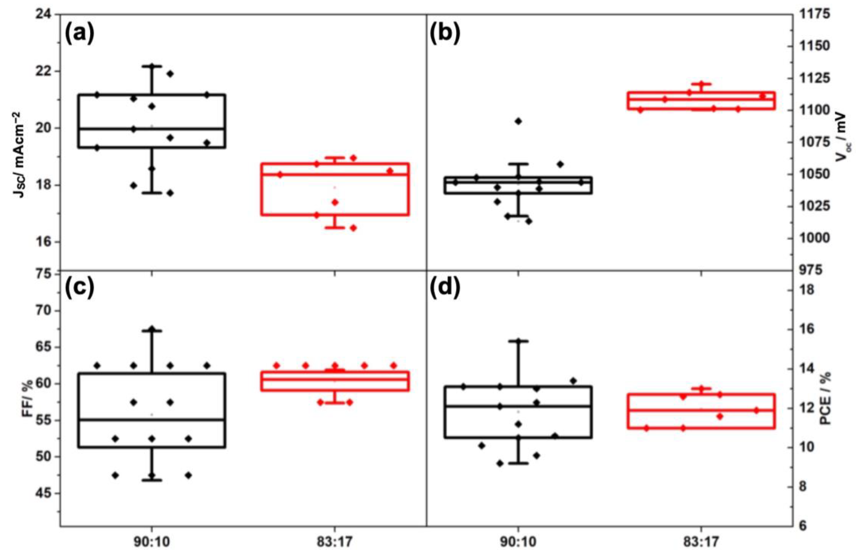
| I:Br | Back Contact | VOC (avg) (mV) | JSC (avg) (mAcm−2) | FF (avg) (%) | PCE (avg) (%) |
|---|---|---|---|---|---|
| 90:10 | Gold | 1031.86 ± 32.29 | 21.31 ± 2.36 | 66.79 ± 5.66 | 14.64 ± 1.84 |
| Carbon | 1042.47 ± 19.24 | 20.08 ± 1.44 | 55.79 ± 6.78 | 11.82 ± 1.79 | |
| 83:17 | Gold | 1058.05 ± 48.90 | 19.21 ± 1.82 | 70.86 ± 4.26 | 14.39 ± 1.71 |
| Carbon | 1108.15 ± 7.65 | 17.92 ± 0.96 | 60.34 ± 1.61 | 11.97 ± 0.82 |
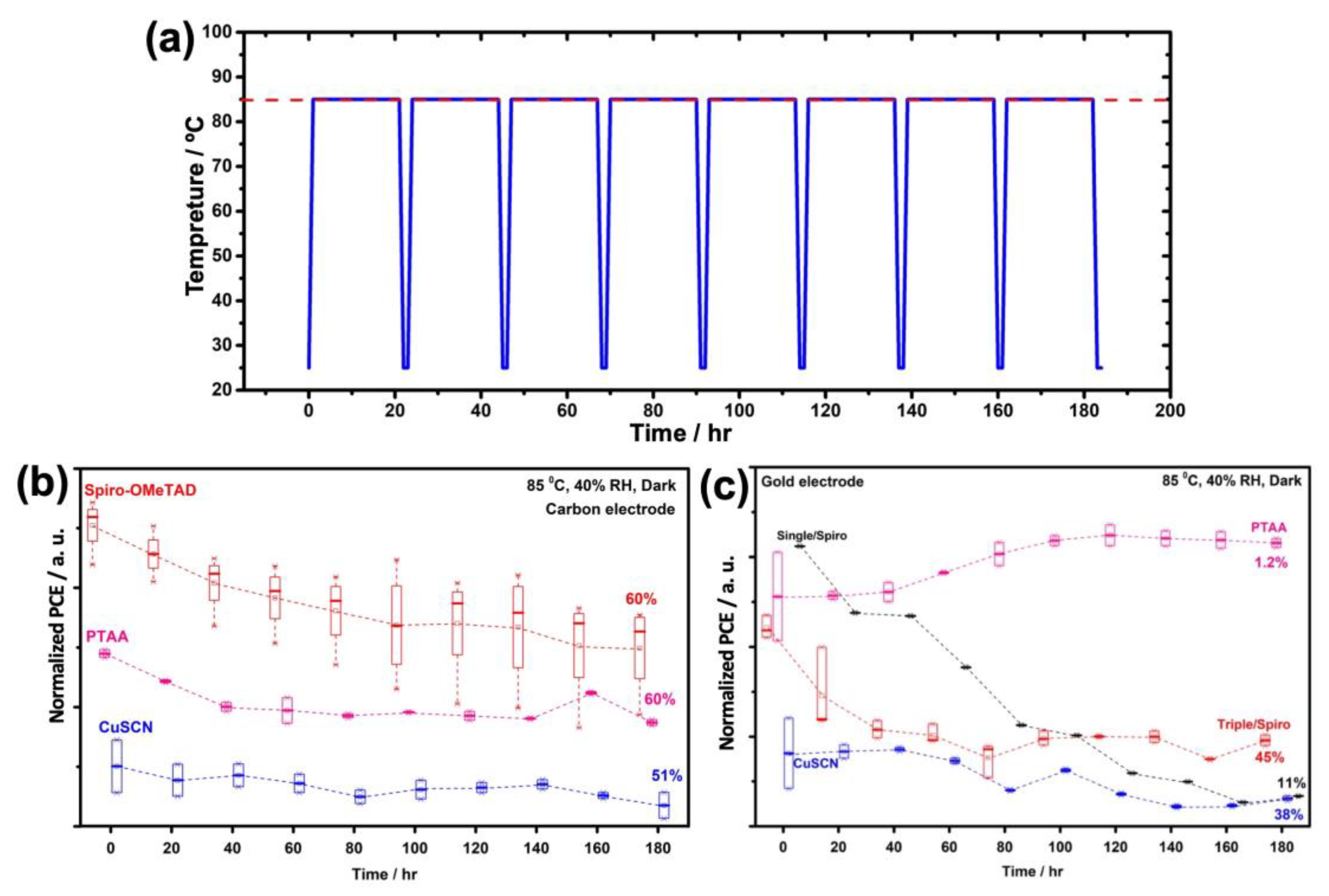
| HTM | Back Contact | VOC (V) | JSC (mA cm−2) | FF (%) | PCE (max) (%) |
|---|---|---|---|---|---|
| Spiro-OMeTAD | Gold | 1.09 | 23.23 | 72.8 | 18.3 |
| Carbon | 1.04 | 21.83 | 67.3 | 15.3 | |
| PTAA | Gold | 1.01 | 19.27 | 72.2 | 15.3 |
| Carbon | 0.94 | 15.66 | 41.2 | 6.1 | |
| CuSCN | Gold | 0.92 | 10.75 | 63.7 | 6.3 |
| Carbon | 0.92 | 13.25 | 45.5 | 5.6 |
| HTM | Back Contact | VOC (avg) (mV) | JSC (avg) (mA cm−2) | FF (avg) (%) | PCE (avg) (%) |
|---|---|---|---|---|---|
| Spiro-OMeTAD | Gold | 1009.03 ± 47.98 | 19.49 ± 3.52 | 67.29 ± 5.57 | 13.23 ± 2.71 |
| Carbon | 1041.76 ± 18.56 | 19.81 ± 2.05 | 57.10 ± 6.77 | 12.06 ± 1.96 | |
| PTAA | Gold | 1058.29 ± 26.31 | 17.24 ± 1.42 | 69.03 ± 3.66 | 12.65 ± 1.83 |
| Carbon | 935.12 ± 43.52 | 12.60 ± 1.93 | 36.34 ± 7.70 | 4.35 ± 1.32 | |
| CuSCN | Gold | 923.10 ± 8.94 | 7.52 ± 2.17 | 72.7 ± 8.59 | 5.00 ± 0.88 |
| Carbon | 967.67 ± 51.29 | 6.90 ± 3.01 | 43.03 ± 4.43 | 2.92 ± 1.35 |
| Densification by HTM | VOC (V) | JSC (mAcm−2) | FF (%) | PCE(max) (%) |
|---|---|---|---|---|
| Without | 0.99 | 14.39 | 31.3 | 4.4 |
| With | 1.04 | 21.17 | 47.8 | 10.6 |
| I:Br | VOC (V) | JSC (mAcm−2) | FF (%) | PCE(max) (%) |
|---|---|---|---|---|
| 90:10 | 1.03 | 19.70 | 63.32 | 12.88 |
Disclaimer/Publisher’s Note: The statements, opinions and data contained in all publications are solely those of the individual author(s) and contributor(s) and not of MDPI and/or the editor(s). MDPI and/or the editor(s) disclaim responsibility for any injury to people or property resulting from any ideas, methods, instructions or products referred to in the content. |
© 2023 by the authors. Licensee MDPI, Basel, Switzerland. This article is an open access article distributed under the terms and conditions of the Creative Commons Attribution (CC BY) license (https://creativecommons.org/licenses/by/4.0/).
Share and Cite
Rahighi, R.; Gholipour, S.; Amin, M.A.; Ansari, M.Z. Hole-Transport Material Engineering in Highly Durable Carbon-Based Perovskite Photovoltaic Devices. Nanomaterials 2023, 13, 1417. https://doi.org/10.3390/nano13081417
Rahighi R, Gholipour S, Amin MA, Ansari MZ. Hole-Transport Material Engineering in Highly Durable Carbon-Based Perovskite Photovoltaic Devices. Nanomaterials. 2023; 13(8):1417. https://doi.org/10.3390/nano13081417
Chicago/Turabian StyleRahighi, Reza, Somayeh Gholipour, Mohammed A. Amin, and Mohd Zahid Ansari. 2023. "Hole-Transport Material Engineering in Highly Durable Carbon-Based Perovskite Photovoltaic Devices" Nanomaterials 13, no. 8: 1417. https://doi.org/10.3390/nano13081417
APA StyleRahighi, R., Gholipour, S., Amin, M. A., & Ansari, M. Z. (2023). Hole-Transport Material Engineering in Highly Durable Carbon-Based Perovskite Photovoltaic Devices. Nanomaterials, 13(8), 1417. https://doi.org/10.3390/nano13081417