Article

Improvement of Corrosion Resistance of Stainless Steel Welded Joint Using a Nanostructured Oxide Layer

1
Department of Nuclear and Quantum Engineering, Korea Advanced Institute of Science and Technology (KAIST), Daejeon 34141, Korea
2
Department of Chemical Engineering, Khalifa University of Science and Technology, Abu Dhabi 127788, United Arab Emirates
*
Author to whom correspondence should be addressed.
Nanomaterials 2021, 11(4), 838; https://doi.org/10.3390/nano11040838
Submission received: 8 March 2021 / Revised: 17 March 2021 / Accepted: 22 March 2021 / Published: 25 March 2021
(This article belongs to the Special Issue Advances in Electrochemical Fabrication of Nanoporous Materials)

Abstract

:
In this study, we fabricated a nanoporous oxide layer by anodization to improve corrosion resistance of type 304 stainless steel (SS) gas tungsten arc weld (GTAW). Subsequent heat treatment was performed to eliminate any existing fluorine in the nanoporous oxide layer. Uniform structures and compositions were analyzed with field emission scanning electron microscope (FESEM) and X-ray diffractometer (XRD) measurements. The corrosion resistance of the treated SS was evaluated by applying a potentiodynamic polarization (PDP) technique and electrochemical impedance spectroscopy (EIS). Surface morphologies of welded SS with and without treatment were examined to compare their corrosion behaviors. All results indicate that corrosion resistance was enhanced, making the treatment process highly promising.

1. Introduction

Stainless steel can be classified into different types based on its composition. Type 304 SS is the most widely used austenitic SS, which is primarily composed of Fe, Cr, Ni, and Mn. Non-iron elements are added mostly to improve the corrosion and heat resistance of SS [1,2,3]. In particular, chromium, which constitutes over 11% of type 304 SS in mass, is responsible for the formation of passive films [4,5,6] that provide significant protection from corrosion. Furthermore, in the presence of oxygen, chromium is able to repair these passive films [5,7,8]. Overall, type 304 SS exhibits superb mechanical strength [9,10], high ductility [10], and high corrosion [1,8,11,12] and heat resistance [13], making it highly versatile. Due to this versatility, the SS is used in industries involved in mining, petroleum processing, metal processing, nuclear engineering, underwater construction and additive manufacturing [14,15]. However, all these applications require some degree of welding, diminishing the corrosion resistance of the SS.
Although type 304 SS is generally corrosion resistant, it is occasionally susceptible to localized corrosion in chloride environments; pitting [16,17], intergranular corrosion [18], and stress corrosion cracking (SCC) [17,19] can occur in such conditions. Welding SS makes it even more susceptible to corrosion due to the metallurgical and microstructural changes and the mechanical stress induced by the process [20,21,22]. The microstructural phase of type 304 SS is typically austenite. However, the rapid heating and cooling process involved in welding causes the phase to transition from austenite to delta ferrite as reported in past work [21,23]. Additionally, arc welding, the most common form of welding, causes grain coarsening [24,25] and sensitization [26,27] by precipitating chromium carbides along the grain boundaries at heat affected zones (HAZ). Chromium carbide precipitation leads to chromium depletion, which ultimately reduces the corrosion resistance of the SS. Moreover, SCC can occur from the mechanical stress resulting from welding and any additional processing.
To address these issues, several measures are currently taken. Heat treatment coupled with water quenching is widely used to avoid sensitization and sigma-phase embrittlement [28]. Furthermore, low carbon or stabilized grade alloys can also be used to mitigate sensitization [29,30]. Nonetheless, these procedures require the use of complex equipment at ultra-high temperatures and are expensive to undertake. Recently, a few studies were carried out to enhance the corrosion resistance of SS without utilizing the aforementioned methods. In one study [31], polypyrrole (PPA)-based coating containing polydapamine functionalized carbon powder (C-PDA) was applied, while, in another study [32], graphene oxide (GO) coating was applied. These studies provided great insight into how coating could be used to enhance the corrosion resistance of SS.
In this paper, we propose a simple approach to improving corrosion resistance of type 304 SS weld in a chloride environment using a one-step anodization process. A nanoporous oxide layer was fabricated on the surface of type 304 SS with GTAWs via anodization, after which, the SS was heat-treated to eliminate any existing fluorine. Results show that the anodization process coupled with the heat treatment provides significant corrosion protection to the SS and the welds. Furthermore, the proposed methodology has distinct advantages of being simple, safe, low-cost, and versatile, making it highly promising in numerous fields [33,34,35].

2. Materials and Methods

2.1. Sample Preparation

Type 304 SS comprising 18 wt% Cr, 8 wt% Ni, 2 wt% Mn and 72 wt% Fe was used in this research. Autogenous gas tungsten arc welding was performed on the SS to create welds with a chemical composition identical to that of the SS [17]. The SS samples were circular in shape with a diameter of 13 mm and a thickness of 1 mm. A handle was attached to each sample to perform the anodization process as shown in Figure 1a. Prior to anodization, the samples were polished with SiC polishing papers and sonicated in acetone diluted with distilled water for 15 min. The samples were then stored in an oven at 60 °C. Ethylene glycol (REAGENTPLUS, ≥99%) and ammonium fluoride (NH4F) were obtained from Sigma-Aldrich (St. Louis, MO, USA) and were used to create the electrolyte for anodization.

2.2. Anodization and Heat Treatment

The anodization process was carried out with two electrodes; one SS weld sample served as the working electrode and a platinum sheet (15 mm × 40 mm × 0.5 mm) served as the counter electrode. Anodization was performed at a constant current density of 100 A/m2 in an ethylene glycol-based electrolyte solution containing 0.1 M NH4F and 0.1 M H2O for 7 min. A cooling bath was used to maintain the temperature of the electrolyte solution at 25 °C. After anodization, the samples were submerged in ethanol for 1 h and dried in a vacuum oven at 50 °C.
To eliminate fluorine, heat treatment was carried out on the anodized samples at 500 °C for 1 h in air. To avoid cracking of the oxide films formed on the welded SS samples, a relatively low heating rate of 2 °C/min. was used. After heat treatment, the samples were gradually cooled to room temperature.

2.3. Characterization

Surface morphologies of the samples were examined with a field emission scanning electron microscope (FESEM, Hitachi SU5000, Tokyo, Japan). The chemical composition of the fabricated nanoporous oxide layers was determined with a high-resolution powder X-ray diffractometer (XRD, Rigaku, Japan). Cross-sectional data for the nanoporous oxide layers, such as the chemical composition by depth, was obtained by employing a focused ion beam (FIB) and observing with a SEM (Helios Nanolab 450 F1, FEI, Milpitas, CA, USA). Corrosion properties of the samples were evaluated by applying the potentiodynamic polarization (PDP) technique and electrochemical impedance spectroscopy (EIS) using Reference 600 Potentiostat/Galvanostat (Gamry, Warminster, PA, USA). Corrosion rates and all variables related to corrosion were determined by averaging five values obtained from five separate measurements.

2.4. Corrosion Test

A conventional three electrode cell system was adopted. One sample with an exposed area of 0.2 cm2 was used as the working electrode, a platinum wire was used as the counter electrode, and a saturated calomel electrode was used as the reference electrode. Firstly, PDP test was performed to compare the corrosion susceptibilities of normal SS welds, anodized welds, and heat-treated anodized welds. Prior to testing, stable open circuit potential (OCP) was achieved and maintained for 1200 s. The potential applied during PDP ranged from −600 to 600 mV with respect to the OCP, and the scan rate was set to 0.333 mV/s.
Electrochemical impedance spectroscopy (EIS) was conducted with a sinusoidal amplitude of 10 mV. The impedance spectra were collected with 5 points per decade over a frequency range of 105 to 10−2 Hz. The spectra were analyzed using Echem Analyst software (Gamry). All the corrosion tests were carried out at room temperature in artificial seawater with a chemical composition (Table 1) that is nearly identical to that of real seawater.

3. Results and Discussion

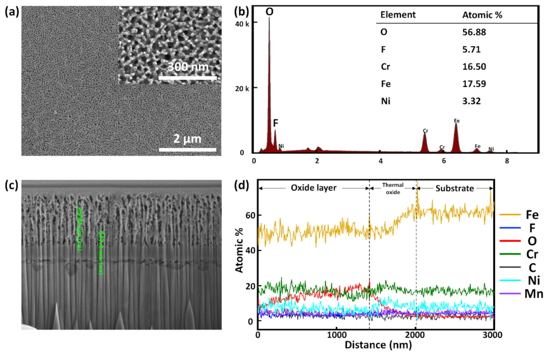
3.1. Anodized SS Weld

A welding joint can have different zones: a weld zone (WZ), a heat affected zone (HAZ), and a base metal (BM) zone. Figure 2 shows the metallographs of the three aforementioned zones. A weld zone can exhibit two phases, austenite and ferrite, as shown in the XRD patterns (Figure 3a). It is widely known that a small amount of δ-ferrite is necessary to avoid thermal cracking during cooling [20,21,36]. However, to enhance corrosion resistance, δ-ferrite content has to be reduced. δ-ferrite traps more chromium than austenite, resulting in insufficient chromium content adjacent to the grain boundaries of the former [37,38]. Moreover, previous works have shown [37,39,40] that chromium carbides (Cr23C6) start to precipitate along the δ-ferrite/austenite interfaces at a temperature of 400~800 °C. These phenomena cause chromium-depleted regions to form near grain boundaries, making welded SS susceptible to corrosion. Figure 2a,b are SEM images of a SS weld surface, showing a dendritic structure with dark δ-ferrite encased in a bright austenite matrix and chromium carbide that has precipitated along the δ-ferrite/austenite interfaces, respectively. Figure 2c shows that the grain size in the HAZ is slightly larger than that found in the BM zone. It has been previously reported that the HAZ is very susceptible to pitting corrosion due to the process of recrystallization and stress accumulation resulting from heating [41].
A SS weld was electrochemically anodized in NH4F-based electrolyte for less than 10 min at 298 K and at a constant current density of 100 A/m2. The current was kept constant to fabricate an oxide layer with uniform nanopores. A distinct color change of the SS surface was observed after anodization (Figure 1b), and FESEM images taken of the surface (Figure 4a) revealed that a nanoporous oxide layer with an average pore diameter of nearly 40 ± 5 nm was fabricated. The pore diameter was determined from averaging values obtained from 50 separate measurements utilizing the built-in software of the FESEM used in this work. The fabricated pores were relatively uniform. EDX measurement (Figure 4b) indicated that the oxide layer was primarily composed of iron and fluorine. The major presence of Fe can be explained by the fact that Fe is the primary constituent of SS. As for F, its presence in the electrolyte can be used to explain its presence in the oxide layer. The equations below show the oxidation and dissolution reactions taking place during anodization.
2H2O → O2 + 4H+ + 4e
2Fe + 3/2O2 → Fe2O3
Fe2O3 + 6H+ + 12F → 2[FeF3]3 + 3H2O
During anodization, nanopores were fabricated by dissolution of fluorine, indicating that the competition between oxidation and F dissolution determines the morphology of the resulting nanoporous structure. Cross-sectional FESEM images show that the average length obtained from five measurements of the nanopores was 1.986 ± 0.102 μm (Figure 4c). The oxide layer can be clearly distinguished from the substrate as the former exhibits much higher F and O contents than the latter (Figure 4d).

3.2. Heat Treatment

The anodization process creates a nanoporous oxide layer with a high F content. The F compounds found in the oxide layer seriously degrade the layer when it is exposed to an aqueous environment for an extended period. Thus, to eliminate these detrimental compounds, heat treatment was performed at 500 °C for 1 h in air. FESEM images of the heat-treated sample surface (Figure 5a) indicate that the morphology of the nanoporous structure remains relatively unaltered, but the pore diameter increases slightly to about 58 ± 11 nm after heat treatment. The increased pore diameter was determined by averaging values obtained from 50 separate measurements using the built-in software of the FESEM. EDX measurement (Figure 5b) shows that heat treatment causes the F content to decrease to a negligible amount, while steeply increasing the oxygen content. Furthermore, the heat treatment process generated phases [42] other than austenite or δ-ferrite in the nanoporous oxide layer that was largely amorphous prior to the treatment. XRD measurements (Figure 3c) show that the new phases that formed were hematite (Fe2O3) and magnetite (Fe3O4); of the two, the latter was much more prevalent. Due to its chemical stability [43,44], the magnetite provides significant protection to the fabricated nanoporous oxide layer.
Cross-sectional analysis of the heat-treated sample (Figure 5c,d) showed that the thickness of the overall oxide layer remained relatively unchanged from the thickness prior to the heat treatment, which was approximately 2 μm (Figure 5c). However, the treatment caused a non-porous thermal oxide layer with a thickness of nearly 547.8 ± 6.2 nm to form underneath the nanoporous oxide layer (Figure 5c), slightly thinning the latter layer. The thickness value of the non-porous oxide layer was determined by averaging values obtained from five measurements using the built-in software of the FESEM. Further oxidation will be difficult due to the presence of this compact thermal oxide layer. EDX measurement (Figure 5d) shows that the heat treatment drastically eliminates fluorine, causing further thinning of the nanoporous layer.

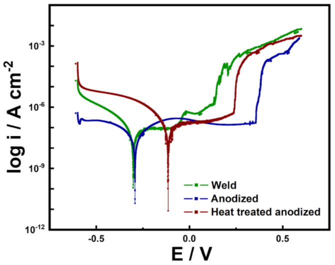
3.3. Potentiodynamic Polarization Test

Potentiodynamic polarization (PDP) tests were performed on a plain SS weld, an anodized welded SS, and a heat-treated anodized welded SS in artificial seawater. By extrapolating from the fitted anodic and cathodic Tafel plots, corrosion potential (Ecorr), and corrosion current (icorr) can be calculated. Ecorr and icorr quantify the likelihood of corrosion and the severity of incurred corrosion, respectively. Corrosion rate (CR) can be calculated by inputting icorr. Pitting potential (Epit), also known as breakdown potential, is defined as the potential at which passive film breakdown occurs. Epit can be easily identified in the polarization curve as the starting point of sharp current increase. To accurately determine Epit, the international standard (ISO 15158-2014) of setting the potential corresponding to 100 uA/cm2 as Epit was adopted. The interval between Ecorr and Epit is known as the passive stability region and is the potential range within which stable protective passive film is preserved.
Figure 6 shows the PDP curves of the samples. All relevant parameters are tabulated in Table 2. In comparison to the plain SS weld, the anodized and heat-treated anodized counterparts displayed significantly higher Ecorr, demonstrating that the presence of a nanoporous oxide layer significantly reduces the possibility of corrosion. Among the two samples with high Ecorr, the heat-treated anodized sample was especially high, which seems to be due to the chemically stabilized oxide layer by heat treatment. The icorr values of the plain, the anodized, and the heat-treated anodized welded SS were determined to be 1.788 × 10⁻⁷ A/cm2, 1.118 × 10⁻⁷ A/cm2, and 0.464 × 10⁻⁷ A/cm2, respectively. These values show that the plain SS weld suffers much more severely from corrosion than the other two samples do. The corrosion resistance of the two anodized samples can be attributed to the presence of the protective oxide layer, which hinders the permeation of aggressive ions. The additional corrosion resistance displayed by the heat-treated anodized welded SS can be attributed to the formation of a compact thermal oxide layer and the stabilization of the nanoporous oxide layer resulting from fluorine elimination. Assuming uniform corrosion at the surface, corrosion rate (mm year1) can be calculated [45] by using the equation below:
CR mm   y e a r 1   =     i c o r r A c m 2 × M g n × d g c m 3 × A c m 2   × 3272  
As tabulated in Table 2, the corrosion rates of the plain SS weld, the anodized welded SS and the heat-treated anodized welded SS were calculated to be 6.484 × 10⁻³ mmy−1, 4.055 × 10⁻³ mmy−1 and 1.683 × 10⁻³ mmy−1, respectively. The anodized samples also exhibited higher Epit values than the plain sample, indicating that the former samples are less likely to experience localized corrosion than the latter. The passive stability region (Epit-Ecorr) was also expectedly larger for the anodized samples than the plain sample, demonstrating that anodization enhances passivation behavior [32]. Interestingly, the case of the heat-treated anodized sample showed a lower Epit than that of anodized welded SS, which can be attributed to the fact that a small amount of carbides was generated because the heat treatment temperature slightly spans the carbide formation temperature range. However, the degree was so insignificant that it seems to be negligible. Additionally, even with a large Epit, extended submersion in water is not possible with the anodized welded SS; therefore, heat-treated anodized welded SS was evaluated to be the most corrosion resistant sample of the three.

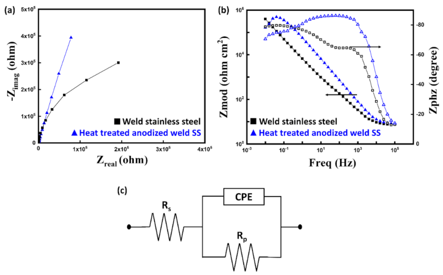
3.4. Electrochemical Impedance Spectroscopy

Electrochemical impedance spectroscopy (EIS) is widely used [46,47] to evaluate the corrosion resistance property of anodic films. Figure 7 shows the impedance spectra of the SS weld and the heat-treated anodized welded SS. The linear sections in the Bode plots (Figure 7b) have a slope of near −1 and a phase angle of ~80°. These features are generally observed in metals coated with a passive film [48,49]. At low frequencies, the two plots show small discrepancies, possibly resulting from impurities at the surface [42]. The Niquist plots (Figure 7a) show a larger radius of depressed capacitive semicircle for the heat-treated anodized welded SS than for the plain SS weld, indicating higher impedance of the former. For numerical analysis, a constant phase element (CPE)-based Randles circuit (Figure 7c) was used for fitting [50,51]. The Randles circuit is composed of an active solution resistance (Rs), a polarization resistance (Rp), and CPE. Capacitance was replaced with CPE to obtain a more accurate analysis of corrosion behavior. Impedance of CPE is calculated as follows:
ZCPE = Y1 (iw)−n
where Y is the admittance magnitude, w is the angular frequency and n signifies the phase shift. The case when n = 0, −1, and 1 describe a pure resistor, a pure inductor and an ideal capacitor, respectively.
All relevant parameters are tabulated in Table 3. The polarization resistances (Rp) of the bare SS weld, and heat-treated anodized welded SS were calculated to be 809 kΩ cm2 and 1756 kΩ cm2, respectively; a higher polarization resistance (Rp) value indicates superior corrosion resistance. The capacitance can be also calculated using the equation below to evaluate the samples.
C = Y1/n R(1−n)/n
Higher capacitance indicates higher chance of corrosion [52]. The heat-treated anodized sample and the bare sample exhibited capacitance values of 40.54 μF/cm2 and 45.04 μF/cm2, respectivtabely. As stated before, the fabricated nanoporous oxide layer provides protection from corrosion and the dense thermal oxide layer increases the polarization resistance (Rp) by providing barrier resistance.

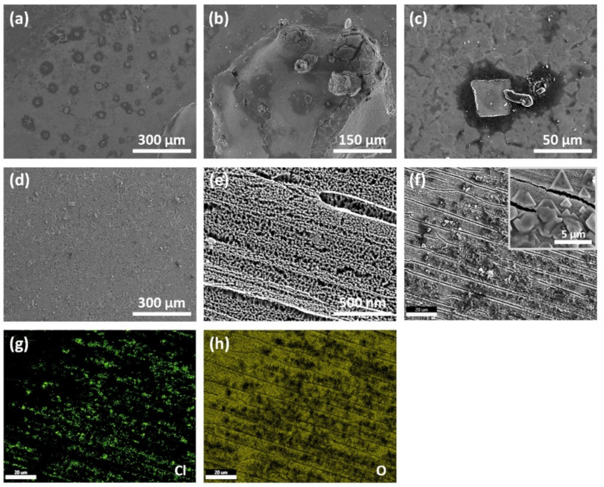
3.5. Surface Morphology after Corrosion Test

An electrochemical corrosion test evaluates the performance of samples in a relevant environment by simulating the exposure that the samples would receive if placed in the said environment [53]. Figure 8a–c shows a microscopic image of the SS weld surface after the corrosion test. The images (Figure 8a,c) reveal countless signs of severe corrosion with desorption through the surface shell being observable. Figure 8b shows a large pit, resulting from localized corrosion, found on the surface. Such pitting corrosion can potentially facilitate stress corrosion cracking (SCC) as pits are more susceptible mechanical damage.
Figure 8d–h shows the surface of heat-treated anodized welded SS after the corrosion test. No severe pits are noticeable with only minor pits and signs of corrosion being observable in the low-magnification microscopic image (Figure 8d). Figure 8f shows large amounts of crystals that have accumulated on top of the nanoporous oxide layer, while its inset shows the morphology of the crystals. EDX characterization was performed on the crystals, and the results are shown in the Figure 8g,h; the results indicate that the crystals are chloride-based. The presence of these chloride crystals demonstrates that the stable magnetite (Fe3O4) layer successfully prevented chlorine ions from penetrating and causing deep corrosion. Figure 8h shows that oxide materials are present at the surface, further cementing the role of the magnetite. Lastly, the structural integrity of the nanopores was maintained after the corrosion (Figure 8e), signifying that the fabricated nanoporous oxide layer is highly durable.

4. Conclusions

In this study, corrosion resistance of type 304 SS GTAW joint was enhanced by employing a one-step electrochemical anodization process. The anodization process was conducted in a NH4F-based ethylene glycol electrolyte to produce a nanoporous oxide layer on the surface of a SS weld. To eliminate fluorine from the layer, heat treatment was undergone at 773 K for 1 h. While the heat treatment was successful at removing fluorine, it also induced the oxide layer to crystallize into hematite (Fe2O3) and magnetite (Fe3O4) and created a compact non-porous thermal oxide layer underneath the nanoporous layer. Electrochemical corrosion test in artificial seawater showed that the anodization process coupled with the heat treatment significantly enhanced the corrosion resistance of a SS weld. After the corrosion test, the bare SS weld exhibited numerous signs of corrosion products, while the heat-treated anodized welded SS exhibited accumulation of chloride crystals at the surface, signifying that the damaging ions could not penetrate the oxide layer. These results show that the enhancement method described in this paper is highly effective. Furthermore, the anodization method is simple, safe, low-cost and versatile, making it highly promising in many fields.

Author Contributions

Conceptualization and methodology, J.H., A.A., and S.O.C.; formal analysis and investigation, J.H., S.Y.L., and J.L.; writing—original draft preparation, writing—review and editing, all authors. All authors have read and agreed to the published version of the manuscript.

Funding

This research was funded by the National Research Foundation of Korea (NRF) grant funded by the Korean Government, grant number NRF-2019M2D2A1A02058174.

Institutional Review Board Statement

Not applicable.

Informed Consent Statement

Not applicable.

Data Availability Statement

Data sharing is not applicable to this article.

Conflicts of Interest

The authors declare no conflict of interest.

References

  1. Fahim, A.; Dean, A.E.; Thomas, M.D.; Moffatt, E.G. Corrosion resistance of chromium-steel and stainless steel reinforcement in concrete. Mater. Corros. 2019, 70, 328–344. [Google Scholar] [CrossRef]
  2. Muthupandi, V.; Srinivasan, P.B.; Shankar, V.; Seshadri, S.K.; Sundaresan, S. Effect of nickel and nitrogen addition on the microstructure and mechanical properties of power beam processed duplex stainless steel (UNS 31803) weld metals. Mater. Lett. 2005, 59, 2305–2309. [Google Scholar] [CrossRef]
  3. Mosecker, L.; Pierce, D.T.; Schwedt, A.; Beighmohamadi, M.; Mayer, J.; Bleck, W.; Wittig, J.E. Temperature effect on deformation mechanisms and mechanical properties of a high manganese C + N alloyed austenitic stainless steel. Mater. Sci. Eng. A 2015, 642, 71–83. [Google Scholar] [CrossRef]
  4. Jiang, R.; Wang, Y.; Wen, X.; Chen, C.; Zhao, J. Effect of time on the characteristics of passive film formed on stainless steel. Appl. Surf. Sci. 2017, 412, 214–222. [Google Scholar] [CrossRef]
  5. Kim, J.J.; Young, Y.M. Study on the passive film of type 316 stainless steel. Int. J. Electrochem. Sci. 2013, 8, 11847–11859. [Google Scholar]
  6. Okamoto, G. Passive film of 18–8 stainless steel structure and its function. Corros. Sci. 1973, 13, 471–489. [Google Scholar] [CrossRef]
  7. Agrawal, H.; Sharma, P.; Tiwari, P.; Taiwade, R.V.; Dayal, R.K. Evaluation of self-healing behaviour of AISI 304 stainless steel. Trans. Indian Inst. Met. 2015, 68, 501–511. [Google Scholar] [CrossRef]
  8. Wang, Q.; Zhang, B.; Ren, Y.; Yang, K. A self-healing stainless steel: Role of nitrogen in eliminating detrimental effect of cold working on pitting corrosion resistance. Corros. Sci. 2018, 145, 55–66. [Google Scholar] [CrossRef]
  9. Lula, R.A. Stainless Steel. OSTI 7204462. USA, 1985. [Google Scholar]
  10. Saeidi, K.; Zapata, D.L.; Lofaj, F.; Kvetkova, L.; Olsen, J.; Shen, Z.; Akhtar, F. Ultra-high strength martensitic 420 stainless steel with high ductility. Addit. Manuf. 2019, 29, 100803. [Google Scholar] [CrossRef]
  11. Nishimoto, K.; Ogawa, K. Corrosion properties in weldments of stainless steels (1). Metallurgical factors affecting corrosion properties. Weld. Int. 1999, 13, 845–854. [Google Scholar] [CrossRef]
  12. Ping, G.; Elliott, S.; Beaudoin, J.J.; Arsenault, B. Corrosion resistance of stainless steel in chloride contaminated concrete. Cem. Concr. Res. 1996, 26, 1151–1156. [Google Scholar] [CrossRef]
  13. Cheng, X.; Feng, Z.; Li, C.; Dong, C.; Li, X. Investigation of oxide film formation on 316 L stainless steel in high-temperature aqueous environments. Electrochim. Acta 2011, 56, 5860–5865. [Google Scholar] [CrossRef]
  14. Hassan, A.J.; Boukharouba, T.; Miroud, D. Friction welding of AISI 304: Effect of friction time on micro-structure, micro-hardness and tension-compression properties. Acta Metall. Slovaca 2020, 26, 78–83. [Google Scholar] [CrossRef]
  15. Petrousek, P.; Kvackaj, T.; Kocisko, R.; Bidulska, J.; Luptak, M.; Manfredi, D.; Grande, M.A.; Bidulsky, R. Influence of cryorolling on properties of L-PBF 316 L stainless steel tested at 298 K and 77 K. Acta Metall. Slovaca 2019, 25, 283–290. [Google Scholar] [CrossRef] [Green Version]
  16. Tsutsumi, Y.; Nishikata, A.; Tsuru, T. Pitting corrosion mechanism of Type 304 stainless steel under a droplet of chloride solutions. Corros. Sci. 2007, 49, 1394–1407. [Google Scholar] [CrossRef]
  17. Lu, B.T.; Chen, Z.K.; Luo, J.L.; Patchett, B.M.; Xu, Z.H. Pitting and stress corrosion cracking behavior in welded austenitic stainless steel. Electrochim. Acta 2005, 50, 1391–1403. [Google Scholar] [CrossRef]
  18. Alyousif, O.M.; Nishimura, R. The stress corrosion cracking behavior of austenitic stainless steels in boiling magnesium chloride solutions. Corros. Sci. 2007, 49, 3040–3051. [Google Scholar] [CrossRef]
  19. Mayuzumi, M.; Tani, J.; Arai, T. Chloride induced stress corrosion cracking of candidate canister materials for dry storage of spent fuel. Nucl. Eng. Des. 2008, 238, 1227–1232. [Google Scholar] [CrossRef]
  20. Moteshakker, A.; Danaee, I. Microstructure and corrosion resistance of dissimilar weld-joints between duplex stainless steel 2205 and austenitic stainless steel 316 L. J. Mater. Sci. Technol. 2016, 32, 282–290. [Google Scholar] [CrossRef]
  21. Dadfar, M.; Fathi, M.H.; Karimzadeh, F.; Dadfar, M.R.; Saatchi, A. Effect of TIG welding on corrosion behavior of 316 L stainless steel. Mater. Lett. 2007, 61, 2343–2346. [Google Scholar] [CrossRef]
  22. Wang, W.; Hu, Y.; Zhang, M.; Zhao, H. Microstructure and mechanical properties of dissimilar friction stir welds in austenitic-duplex stainless steels. Mater. Sci. Eng. A 2020, 787, 139499. [Google Scholar] [CrossRef]
  23. Yan, J.; Gao, M.; Zeng, X. Study on microstructure and mechanical properties of 304 stainless steel joints by TIG, laser and laser-TIG hybrid welding. Opt. Lasers Eng. 2010, 48, 512–517. [Google Scholar] [CrossRef]
  24. Eroğlu, M.; Aksoy, M.; Orhan, N. Effect of coarse initial grain size on microstructure and mechanical properties of weld metal and HAZ of a low carbon steel. Mater. Sci. Eng. A 1999, 269, 59–66. [Google Scholar] [CrossRef]
  25. Shi, L.; Alexandratos, S.A.; O’Dowd, N.P. Prediction of prior austenite grain growth in the heat-affected zone of a martensitic steel during welding. Int. J. Press. Vessel. Pip. 2018, 166, 94–106. [Google Scholar] [CrossRef]
  26. Umar, S.; Shahi, A.S.; Sharma, V.; Malhotra, D. Effect of welding heat input and post-weld thermal aging on the sensitization and pitting corrosion behavior of AISI 304L stainless steel butt welds. J. Mater. Eng. Perform. 2021, 30, 1–22. [Google Scholar]
  27. Barla, N.A.; Ghosh, P.K.; Kumar, V.; Paraye, N.K.; Anant, R.; Das, S. Simulated stress induced sensitization of HAZ in multipass weld of 304LN austenitic stainless steel. J. Manuf. Process. 2021, 62, 784–796. [Google Scholar] [CrossRef]
  28. Shrikrishna, K.A.; Sathiya, P. Effects of post weld heat treatment on friction welded duplex stainless steel joints. J. Manuf. Process. 2016, 21, 196–200. [Google Scholar]
  29. Trillo, E.A.; Beltran, R.; Maldonado, J.G.; Romero, R.J.; Murr, L.E.; Fisher, W.W.; Advani, A.H. Combined effects of deformation (strain and strain state), grain size, and carbon content on carbide precipitation and corrosion sensitization in 304 stainless steel. Mater. Charact. 1995, 35, 99–112. [Google Scholar] [CrossRef]
  30. Lima, A.S.; Nascimento, A.M.; Abreu, H.F.G.; de Lima-Neto, P. Sensitization evaluation of the austenitic stainless steel AISI 304 L, 316 L, 321 and 347. J. Mater. Sci. 2005, 40, 139–144. [Google Scholar] [CrossRef]
  31. Chen, Z.; Zhang, G.; Yang, W.; Xu, B.; Chen, Y.; Yin, X.; Liu, Y. Superior conducting polypyrrole anti-corrosion coating containing functionalized carbon powders for 304 stainless steel bipolar plates in proton exchange membrane fuel cells. Chem. Eng. J. 2020, 393, 124675. [Google Scholar] [CrossRef]
  32. Mahmoudi, M.; Raeissi, K.; Karimzadeh, F.; Golozar, M.A. A study on corrosion behavior of graphene oxide coating produced on stainless steel by electrophoretic deposition. Surf. Coat. Technol. 2019, 372, 327–342. [Google Scholar] [CrossRef]
  33. Sundarapura, P.; Zhang, X.M.; Yogai, R.; Murakami, K.; Fave, A.; Ihara, M. Nanostructure of porous Si and anodic SiO2 surface passivation for improved efficiency porous Si solar cells. Nanomaterials 2021, 11, 459. [Google Scholar] [CrossRef]
  34. Lee, W.; Ji, R.; Gösele, U.; Nielsch, K. Fast fabrication of long-range ordered porous alumina membranes by hard anodization. Nat. Mater. 2006, 5, 741–747. [Google Scholar] [CrossRef]
  35. De Santis, S.; Sotgiu, G.; Porcelli, F.; Marsotto, M.; Iucci, G.; Orsini, M. A simple cerium coating strategy for titanium oxide nano-tubes’ bioactivity enhancement. Nanomaterials 2021, 11, 445. [Google Scholar] [CrossRef] [PubMed]
  36. Ogawa, T.; Tsunetomi, E. Hot cracking susceptibility of austenitic stainless steels. Weld. J. 1982, 61, 82. [Google Scholar]
  37. Kim, S.H.; Moon, H.K.; Kang, T.; Lee, C.S. Dissolution kinetics of delta ferrite in AISI 304 stainless steel produced by strip casting process. Mater. Sci. Eng. A 2003, 356, 390–398. [Google Scholar] [CrossRef]
  38. Arganis-Juárez, C.R.; Vázquez, A.; Garza-Montes-de-Oca, N.F.; Colás, R. Sensitization of an austenitic stainless steel due to the occurrence of δ-ferrite. Corros. Rev. 2019, 37, 179–186. [Google Scholar] [CrossRef]
  39. Setia, P.; Anand, A.; Venkateswaran, T.; Tharian, K.T.; Singh, S.S.; Mondal, K.; Shekhar, S. Effect of heat treatment on the microstructure evolution and sensitization behavior of high-silicon stainless steel. J. Mater. Eng. Perform. 2020, 29, 6014–6024. [Google Scholar] [CrossRef]
  40. Hu, S.; Mao, Y.; Liu, X.; Han, E.H.; Hänninen, H. Intergranular corrosion behavior of low-chromium ferritic stainless steel without Cr-carbide precipitation after aging. Corros. Sci. 2020, 166, 108420. [Google Scholar] [CrossRef]
  41. Zhu, P.; Cao, X.; Wang, W.; Zhao, J.; Lu, Y.; Shoji, T. An investigation on microstructure and pitting corrosion behavior of 316 L stainless steel weld joint. J. Mater. Res. 2017, 32, 3904–3911. [Google Scholar] [CrossRef]
  42. Saha, S.K.; Park, Y.J.; Kim, J.W.; Cho, S.O. Self-organized honeycomb-like nanoporous oxide layer for corrosion protection of type 304 stainless steel in an artificial seawater medium. J. Mol. Liq. 2019, 296, 111823. [Google Scholar] [CrossRef]
  43. Montoya, P.; Martins, C.R.; de Melo, H.G.; Aoki, I.V.; Jaramillo, F.; Calderón, J.A. Synthesis of polypyrrole-magnetite/silane coatings on steel and assessment of anticorrosive properties. Electrochim. Acta 2014, 124, 100–108. [Google Scholar] [CrossRef]
  44. Atta, A.M.; El-Saeed, A.M.; El-Mahdy, G.M.; Al-Lohedan, H.A. Application of magnetite nano-hybrid epoxy as protective marine coatings for steel. RSC Adv. 2015, 5, 101923–101931. [Google Scholar] [CrossRef]
  45. Bushman, J.B.; Engineer, P.P. Calculation of Corrosion Rate from Corrosion Current (Faraday’s Law); Bushman & Associates Inc.: Medina, OH, USA, 2000. [Google Scholar]
  46. Basak, A.K.; Celis, J.P.; Ponthiaux, P.; Wenger, F.; Vardavoulias, M.; Matteazzi, P. Effect of nanostructuring and Al alloying on corrosion behaviour of thermal sprayed WC-Co coatings. Mater. Sci. Eng. A 2012, 558, 377–385. [Google Scholar] [CrossRef]
  47. Jayaraj, B.; Desai, V.H.; Lee, C.K.; Sohn, Y.H. Electrochemical impedance spectroscopy of porous ZrO2-8 wt.% Y2O3 and thermally grown oxide on nickel aluminide. Mater. Sci. Eng. A 2004, 372, 278–286. [Google Scholar] [CrossRef]
  48. Domínguez-Jaimes, L.P.; Vara, A.M.Á.; Cedillo-González, E.I.; Valdés, R.J.J.; De Damborenea, J.J.; Conde Del Campo, A.; Rodríguez-Varela, F.J.; Alonso-Lemus, I.L.; Hernández-López, J.M. Corrosion resistance of anodic layers grown on 304 L stainless steel at different anodizing times and stirring speeds. Coatings 2019, 9, 706. [Google Scholar] [CrossRef] [Green Version]
  49. Longhitano, G.A.; Conde, A.; Arenas, M.A.; Jardini, A.L.; de Carvalho Zavaglia, C.A.; Maciel Filho, R.; de Damborenea, J.J. Corrosion resistance improvement of additive manufactured scaffolds by anodizing. Electrochim. Acta 2021, 366, 137423. [Google Scholar] [CrossRef]
  50. Heider, B.; Oechsner, M.; Reisgen, U.; Ellermeier, J.; Engler, T.; Andersohn, G.; Sharma, R.; Gonzalez Olivares, E.; Zokoll, E. Corrosion resistance and microstructure of welded duplex stainless steel surface layers on gray cast iron. J. Therm. Spray Technol. 2020, 29, 825–842. [Google Scholar] [CrossRef] [Green Version]
  51. Huang, H.; Qiu, J.; Wei, X.; Sakai, E.; Jiang, G.; Wu, H.; Komiyama, T. Ultra-fast fabrication of porous alumina film with excellent wear and corrosion resistance via hard anodizing in etidronic acid. Surf. Coat. Technol. 2020, 393, 125767. [Google Scholar] [CrossRef]
  52. Zeng, A.; Liu, E.; Annergren, I.F.; Tan, S.N.; Zhang, S.; Hing, P.; Gao, J. EIS capacitance diagnosis of nanoporosity effect on the corrosion protection of DLC films. Diam. Relat. Mater. 2002, 11, 160–168. [Google Scholar] [CrossRef]
  53. Xiao, L.; Peng, J.; Zhang, J.; Ma, Y.; Cai, C.S. Comparative assessment of mechanical properties of HPS between electrochemical corrosion and spray corrosion. Constr. Build. Mater. 2020, 237, 117735. [Google Scholar] [CrossRef]
Figure 1. Digital images of welded SS (a), anodized welded SS (b), and heat-treated anodized welded SS (c).
Nanomaterials 11 00838 g001
Figure 2. Metallurgical field emission scanning electron microscope (FESEM) images of stainless steel (SS) weld zone showing dendrite structure of δ-ferrite (a), chromium carbides (b), heat-affected zone (c), and base metal (d).
Nanomaterials 11 00838 g002
Figure 3. XRD patterns of welded SS (a), anodized welded SS (b), and heat-treated anodized welded SS (c).
Nanomaterials 11 00838 g003
Figure 4. FESEM images showing surface morphologies of anodized welded SS at low and high magnification (a) and EDX characterization of the surface (b). Cross-sectional FESEM image of anodized welded SS (c) and EDX line spectrum of the cross section (d).
Nanomaterials 11 00838 g004
Figure 5. FESEM images showing surface morphologies of heat-treated anodized welded SS at low and high magnification (a) and EDX characterization of the surface (b). Cross-sectional FESEM image of anodized welded SS (c) and EDX line spectrum of the cross section (d).
Nanomaterials 11 00838 g005
Figure 6. Potentiodynamic polarization curves of welded SS, anodized welded SS, and heat−treated anodized welded SS in artificial seawater medium.
Nanomaterials 11 00838 g006
Figure 7. Niquist impedance diagram (a), Bode plot (b) for welded SS and heat-treated anodized welded SS, and equivalent circuit used for fitting (c).
Nanomaterials 11 00838 g007
Figure 8. Surface FESEM images of welded SS (ac). and of heat-treated anodized welded SS (df) after accelerated corrosion test. EDX characterization of crystals (f) on the heat-treated anodized welded SS surface (g,h).
Nanomaterials 11 00838 g008
Table 1. Chemical composition of artificial seawater used for corrosion tests.
ElementComposition (g/L)
Cl19.00
Na9.72
Mg1.30
S0.81
Ca0.40
K0.35
Sr0.007
B0.004
Table 2. Potentiodynamic polarization curve parameters.
SpecimenEcorr (mV/SCE)icorr
(10−7 A cm−2)
Epit(mV)Epit −Ecorr (mV)Corrosion Rate (mm year−1)
Weld−301.0 ± 1.7 1.788 ± 0.020162.6 ± 0.5463.6 ± 2.2(6.484
± 0.073 × 10⁻³
Anodized−290.0 ± 5.41.118 ± 0.102383.6 ± 4.0673.6 ± 9.4(4.055
± 0.370) × 10−3
Heat-treated anodized−114.0 ± 3.50.464 ± 0.094274.8 ± 3.1388.8 ± 6.6(1.683
± 0.341) × 10−3
Table 3. Electrochemical impedance spectroscopy (EIS) parameters with Randles circuit coupled with constant phase element (CPE).
SS WeldHeat-Treated Anodized Welded SS
Rp (kΩ cm2)8091756
Rs (Ω cm2)5.2425.771
Y (μΩ−1sn cm−2)25.6222.13
n0.84310.8581
C (μF cm−2)45.0440.54
Publisher’s Note: MDPI stays neutral with regard to jurisdictional claims in published maps and institutional affiliations.

