Abstract
The amount of encoded data replication in an erasure-coded clustered storage system has a great impact on the bandwidth consumption and network latency, mostly during data reconstruction. Aimed at the reasons that lead to the excess data transmission between racks, a rack aware data block placement method is proposed. In order to ensure rack-level fault tolerance and reduce the frequency and amount of the cross-rack data transmission during data reconstruction, the method deploys partial data block concentration to store the data blocks of a file in fewer racks. Theoretical analysis and simulation results show that our proposed strategy greatly reduces the frequency and data volume of the cross-rack transmission during data reconstruction. At the same time, it has better performance than the typical random distribution method in terms of network usage and data reconstruction efficiency.
1. Introduction
The explosive growth of data volume brings serious challenges to data storage in the age of big data. According to an IDC (Internet Data Center) report, global data volume will grow by 40 percent annually over the next decade, and it is expected to reach 40 ZB by 2020. The distributed storage cluster system is a large-scale distribution storage system, deployed in a clustered way, and is widely used for big data storage due to its low cost. However, the distributed storage cluster system is built on a large amount of cheap storage devices in growing quantity, and even a single device failure may affect the entire system. Thus, the distributed storage cluster system brings more and more challenges in terms of data reliability.
The storage system usually uses replication and erasure codes to ensure data reliability. Replication (data copy) is a redundancy backup method to ensure data availability after device failure, which costs overhead storage space as the scale of the system increases. Erasure codes can provide the same or even higher data reliability with lower storage cost than replication, so it is widely used in storage systems for big data.
In a distribution storage cluster system, it is necessary to cooperate with multiple nodes for implementation of erasure codes, but the frequent data transmission between nodes will take up more network resource in that process. It is necessary to reduce the network traffic since limited network resources are the major bottleneck in the entire system [1]. Besides, reducing network traffic can also shorten data reconstruction time and thus improves overall performance of the storage system. In summary, we propose a rack-aware data placement method for encoded blocks. It uses a single rack to store multiple data blocks of the same file so as to reduce the cross-rack data transmission during data reconstruction.
2. Background and Related Work
2.1. Erasure Coding in Distribution Storage Cluster System
Researchers have extensively studied the application of deploying erasure codes in a distribution storage cluster system. Many measures were taken to improve the performance of erasure-coded clustered storage system, such as simplifying the decoding operation, increasing the number of replicas, or reducing the number of data reconstruction events, etc.
On one hand, it is effective to optimize the erasure code itself. Patrick P.C. Lee and his team have worked on cross-rack network traffic and produced many research results like EAR (Encoding Aware Replication) [2], DRC (Double Regenerating Codes) [3] and CAR (Cross-rack Aware Recovery) [4]. The EAR deploys data blocks in a non-random way before encoding to reduce the data transmission. DRC is a two-stage regeneration so as to minimize the cross-rack repair bandwidth for single-node repair. CAR first examines the data layout in a CFS (Cluster File System) and then determines the recovery solution that accesses the minimum number of racks. BDCode (Big Data Code) [5] is applied to the coding matrix on the basis of CRS (Cauchy Reed-Solomn Codes) to reduce coding costs and times. Li et al. tried to degrade tasks and used the idle network resources to improve network utilization [6]. They also speed up the repair performance in general erasure-coded storage, by pipelining the repair of failed data in small-size units across storage nodes [7]. The DynaEC (Dynamic Erasure Coding) method [8] presents a local coding strategy in HDFS (Hadoop Distributed File System) without downloading data from remote nodes. The Sinbad method [9] adjusts the layout of the replica periodically based on the network balance. Albano [10] reduces the network transmission during encoding and decoding by caching the network storage. Binary regenerating codes [11] reduce the reconstruction bandwidth consumption by simplifying the decoding process. Random binary extension code [12] adjusts the coding matrix flexibly, in order to change the code rate and improve correction ability. CHGDPS [13] combines a consistency hash with the greedy algorithm, on the foundation of dividing the collection and choosing the most suitable node on which to place the multiple redundant blocks.
On the other hand, adding replicas can reduce the number of data reconstruction events. The work on erasure codes that optimize network traffic during regeneration have a long history that can be traced back to A.G. Dimakis’ work (network coding for distributed storage systems). Dimakis and his research team focused on identifying a tradeoff between storage and repair bandwidth [14,15,16,17,18]. Many researchers follow this direction. Lee’s new work RRC (rack-aware regenerating codes) tries to find the optimal tradeoff between storage and repair bandwidth [19]. CAROM [20] uses replication in cooperation with erasure codes to provide the benefits of bandwidth cost, storage cost, and access latencies. Dynamically changing the number of replicas according to the data access frequency can improve storage efficiency and optimize load balancing [21,22]. Adding replicas for hot data can decrease data reconstruction times and improve the storage utilization rate [23]. The mixed storage scheme [24] uses erasure codes and adds a replica at the same time, to improve reliability and storage efficiency. Leveraging a non-linear tradeoff between the recovery bandwidth and the probability of data loss, lazy recovery [25] delays the degraded stripes to amortize repair bandwidth costs. In a word, finding the optimal tradeoff between storage and repair bandwidth in the erasure storage cluster system is demonstrated to improve the data access efficiency to a certain extent.
The above optimizations for erasure codes ignore the effect of the encoded data block layout (node-level or rack-level) on data reconstruction. Although literature [9] gives the layout plan that distributes M + N blocks to M + N nodes, it does not discuss the influence of data distribution between nodes on data reconstruction. The network consumption during data reconstruction mainly takes place in the process of data transmission of all data blocks from different nodes to the decoding node. In general, a typical approach to tolerate node-level and rack-level failures is placing blocks in different nodes where each node belongs to different rack [26,27,28,29,30]. Decoded node and block-stored nodes are usually not directly connected and even across multiple racks, which produces high consumption of network transmission. Meanwhile, existing failure recovery optimizations fail to consider cross-rack repair traffic, as previously mentioned. So, optimization of the data layout is important to reduce the cross-rack transmission frequency and transmission data quantity between nodes, so as to reduce the network resource consumption.
In Reference [31], aiming at the end-to-end delay of data transmission, a multi-path forwarding route is proposed based on cache utilization. The data is sent to the sink node through different parent nodes at a certain probability, which can reduce transmission congestion and the end-to-end delay. At the same time, in Reference [32], a greedy heuristic algorithm is proposed for the on-demand application components placement, which localizes network traffic in the data center interconnect. This optimization helps reduce communication overhead in upper layer network switches and will eventually reduce the overall traffic volume across the data center. A reconstruction of the failed chunk requires a repair server to fetch k chunks (belonging to the same stripe as the failed chunk) from k different servers. This causes the network link into the repair server to become congested, increasing the network transfer time [33]. Thereby, dividing the reconstruction operation into small partial operations and scheduling them on multiple nodes reduces the network pressure. This give us an idea to test whether localizing network traffic can reduce the data transmission and the overall traffic volume during data reconstruction.
Therefore, we put forward a rack aware encoded data placement method from the perspective of the layout of rack level blocks. It uses a rack aware method to organize encoded blocks in order to reduce the cross-rack transmission frequency and transmission data quantity during data reconstruction.
2.2. The Architecture of the Erasure-Coded Clustered System
In the erasure-coded cluster storage system, data blocks and encoding blocks are stored separately in different nodes of different racks. Every rack has several storage nodes, and nodes within the same rack are connected by top-of-rack (TOR) switches, while different racks are connected by a core network. The architecture of the erasure-coded clustered system is illustrated in Figure 1. Data transmission within the rack (intra-rack) depends on TOR and the cross-rack data transmission depends on the core network.
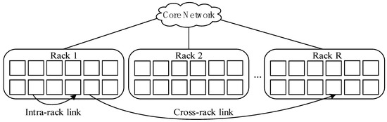
Figure 1.
Hierarchy in the data center.
The stored procedure of each file in an erasure-coded clustered storage system is as follows. Notice that we mark the encoded blocks and parity blocks as (n, k, t, Q).
- (1)
- Divide the data into k blocks;
- (2)
- Perform calculations on the k blocks to generate n (n > k) parity blocks, and store them separately on different server nodes;
- (3)
- When the user visits or node failure occurs, chose t (k ≤ t < n) effective blocks from the alive nodes, and download Q packets of data proportional from each block to decode for recovering the original data.
We always simplify erasure codes mark to (n, k). An (n, k) erasure code can tolerate at most an n − k block loss and at least k blocks are needed to reconstruct the original data. In addition, the maximum short separate (MDS) code can obtain the optimal storage efficiency k/n, which is commonly used in most storage systems. Some commonly used MDS codes include Reed-Solomn code (RS code), low density parity check code (LDPC code), array code, etc.
The mathematical symbols and definitions used in this paper are shown in Table 1.

Table 1.
Mathematical symbols and definitions used in this paper.
In fact, rack failure is very rare in an actual storage system [34], so our research in this paper will only analyze single rack failures.
2.3. Problem Statement
As is known, with erasure code it is easy to obtain the optimal storage efficiency, but it leads to high access latency. One important reason for this is that data blocks and parity blocks are randomly dispersed in different nodes of different racks. This distribution results in additional downloads from any node to get k data blocks (parity blocks) and the process produces a lot of bandwidth latency. Two extreme cases are discussed as followed:
- (1)
- To tolerate any n − k rack failure, it is necessary to place the k data blocks and the r parity blocks of one file in n different racks, meanwhile all these racks are not directly connected and may even be across multiple data centers. This causes a series of performance losses. To recover one failed block, k blocks are required to be downloaded. Although one block can be obtained from inside the same rack, the other k − 1 blocks need to be downloaded from another k − 1 racks, which causes high cross-rack bandwidth transmission and time delay.
- (2)
- All the data blocks and parity blocks are stored in a number of nodes of one rack. This is an assumption and does not generally exist in reality. Data reconstruction in this situation only needs intra-rack transmission, without cross-rack transmission, which reduces transmission delay and improves decoding performance. However, with this layout it is difficult to meet the requirements of rack-level fault tolerance, i.e., once the rack fails then relevant data are unrecoverable, which violates the ability of the erasure codes as a pivotal fault tolerant technology.
Comprehensively taking the above two cases into consideration, it is optimal to distribute blocks between the two extreme cases to ensure rack-level data reliability of a storage system, i.e., blocks of one file distribute not only in different nodes but also in different racks. Therefore, it is of necessity to optimize the layout of encoded data blocks to decrease the frequency and amount of data transfer due to the unavoidably cross-rack transmission. On one hand, cross-rack data transmission takes much more time than intra-rack transmission. That is to say intra-rack takes low transmission time due to the high-speed TOR switch. Commonly, the cross-rack capacity available per node in the worst case is only 1/5 to 1/20 of the intra-rack capacity [35,36,37]. On the other hand, the number of nodes and racks quickly increases with the expansion of the clustered system size, this requires more and more cross-rack transmission, which would give rise to further fierce competition and would easily lead to communication congestion and transmission delay.
3. Rack Aware Encoding Data Placement Schemes
3.1. Design Goals
Considering that cross-rack distribution not only brings more cross-rack transmission but also increases transmission delay when downloading blocks, and that blocks of one file stored in a single rack reduces the fault tolerance level, it is necessary to obtain a tradeoff between transmission efficiency and data reliability. The main goals of the data placement scheme designed in this paper are as follows:
- (1)
- Reduce the cross-rack data transmission. Less frequent data transmission and lower transmission volume lead to better data reconstruction performance.
- (2)
- Maintain data availability. Any of the data layout plans should guarantee rack-level fault tolerance.
3.2. Placement Strategy for Encoded Data Blocks
In an erasure-coded clustered storage system, the original data of size S is encoded into n fragments of size S/k each using an (n, k) MDS erasure code, and these fragments are distributed across n nodes (i.e., one encoded fragment per node) that are evenly located in r racks with n/r nodes in each. As blocks becomes more scattered, cross-rack transmission occurs more frequently and conversely cross-rack transmission becomes less. Therefore, centralized storage of partial blocks will reduce cross-rack data transmission.
Set the parameter c for the maximum number of blocks placed in a rack, and c > 1. It is implied that placing all blocks of a file needs racks (i.e., deploy n blocks in NR racks). Since one file allows at most n − k block loss to obtain rack-level fault tolerance, we can place n − k blocks of a file in at least one rack. Thus, c ≤ n − k and the storage system can tolerate a rack failed at best.
Our placement strategy is shown in Figure 2. With different values of c, select racks and deploy n encoded blocks in these NR racks with c blocks per rack.
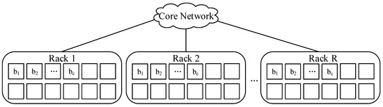
Figure 2.
A kind of placement across R racks.
Notice that in order to reduce intra-rack transmission, it is best to place the c blocks in adjacent nodes, as far as possible. According to our placement strategy, on the basis of ensuring rack-level and node-level failure tolerance, we give the data placement scheme: encode the original data of size S into n fragments; deploy them in NR racks with c blocks per rack, c ≤ n − k.
Take RS (9, 6) as an example, the original data of size S is encoded into 9 fragments, and n = 9, k = 6, c = 3. When c = 2, all data blocks are divided into five parts: {D1, D2}, {D3, D4}, {D5, D6}, {D7, D8}, {D9}, and each part is deployed into a separate rack, either R1, R2, R3, R4, or R5. Notice that blocks are placed in any node within each rack. This specific deployment is shown in Figure 3.
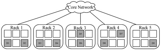
Figure 3.
A kind of placement across 5 racks (c = 2).
Figure 3 shows the placement scheme with c = 2. Under these circumstances, the minimum time of cross-rack transmission during data reconstruction is 2, and the amount of cross-rack transmitted data is 2S/3 at least, that is to say the minimum cross-rack repair bandwidth is 2S/3.
When c = 3, the data blocks are divided into three parts: {D1, D2, D3}, {D4, D5, D6}, {D7, D8, D9}, and each part is deployed into a separate rack, either R1, R2, or R3. Notice that blocks are placed in any node within each rack. This specific deployment is shown in Figure 4.
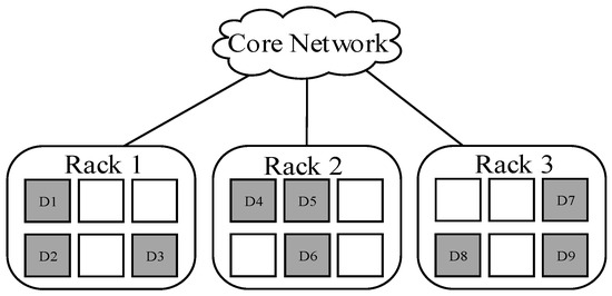
Figure 4.
A kind of placement across 3 racks (c = 3).
Figure 4 shows the placement scheme with c = 3. In this case, the minimum time of cross-rack transmissions during data reconstruction is 1, and the amount of cross-rack transmitted data is S/2 at least, which means the minimum cross-rack repair bandwidth is S/2.
3.3. Data Reliability
The data reliability of the data placement scheme proposed in this paper is analyzed based on a single rack fault. As shown in Figure 5, we discuss whether the data can be recovered when rack 1 fails.
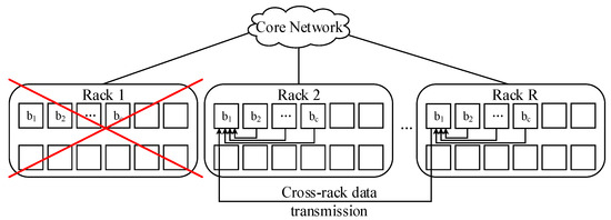
Figure 5.
Data transmission during reconstruction after single rack failure.
It is known that c blocks are placed in each rack. For the case of minimum cross-rack repair bandwidth, c = n − k, i.e., each rack has n − k data blocks of one file. When rack 1 fails, there are still k surviving blocks in the other NR − 1 racks, so the data is fully recoverable. Therefore, the proposed layout scheme can guarantee the data reliability in the case of single-rack failure.
3.4. Placement Algorithm for Encoded Data Blocks
Given the design and analysis in Section 3.2 and Section 3.3, the placement algorithm for encoded data blocks is shown in Algorithm 1.
| Algorithm 1 Algorithm for data placement |
| Input: Original data of size S, the number of blocks placed in one rack c (1 < c ≤ n − k), the optimal rack subset (OPR) |
| Output: Rack location/serial number, the number and size of blocks placed in each rack |
| 1. Initialization: Divide the original data (Size S) into k chunks |
| 2. Encode the k chunks and get r parity chunks |
| 3. Record the data chunks as Di, i = 1, …, n |
| 4. for j = 0, j < NR, j++ |
| 5. for i = 1, i ≤ c, i++ |
| 6. D(c * j + i)—>OPRj |
| 7. end |
First, according to the value of c, we get the number of racks NR that is needed to store a file. Second, we select NR racks from the rack collection. Finally, we deploy n blocks of the file into the chosen racks with c blocks per rack. The pseudocode of the algorithm is shown in Algorithm 1, which mainly implements two functions: (1) dividing and encoding the original file; and (2) selecting NR racks in which to deploy the n encoded blocks. NR racks need to be selected from R before placement. There many possible combinations of any NR racks from R.
To avoid a more centralized placement on fewer rack and cross-rack transmission, we propose an algorithm for load balancing as shown in Algorithm 2. Algorithm 2 compares several alternatives on the basis of available bandwidth from a rack to core network (BA(Rj)) and available storage size in Rj (SA(Rj)), and then finds the optimal rack subset with the maximum RA(APRi).
| Algorithm 2 An algorithm for load balancing |
| Input: The number of blocks placed in one rack c (1 < c ≤ n − k), collection of all racks R, NR |
| Output: The optimal rack subset (OPR) for placing one file |
| 1. Initialization: R = {R1, R2, …, Rm} |
| 2. Select any NR racks from R as a rack-subset |
| 3. Construct THE alternative rack set (APR) that contains all rack-subsets |
| 4. APRl is a rack-subset in APR |
| 5. for each ARPl in ARP do |
| 6. for each Rj in APRl do |
| 7. Get available bandwidth from Rj to core network (BA(Rj)) and available storage size in Rj (SA(Rj)) |
| 8. Calculate BA(APRl)—the sum of BA(Rj) when Rj IS in APRl |
| 9. Calculate SA(ARPl)—the sum of SA(Rj) when Rj IS in APRl |
| 10. RA(APRl) = BA(APRl)/ + SA(ARPl)/ |
| 11. Find the maximum RA(APRl) |
| 12. OPR is the APRl with the maximum RA(APRl) |
| 13. end |
3.5. Extensions
Our method mainly focuses on placement of encoded data blocks, whereas other improved encoding and decoding methods find the optimal coding scheme. There may be a combination of placement methods and coding schemes. For example, using the Locally Repairable Code (LRC) on the basis of the rack aware data block placement method might achieve better performance in terms of network traffic. Generally, the recovery has to deliver the requested data to the repair execution node over racks. Now the system can send the inter-rack blocks first and then decode partial blocks for a single node failure, and also send a decoded block through each cross-rack transmission, which evidently decreases not only each cross-rack but also the overall traffic volume. Further use of the rack aware data placement in other erasure codes and the corresponding load balancing algorithm are considered as our future work.
4. Evaluation and Discussion
4.1. Performance Analysis
The minimum cross-rack repair bandwidth of the two placements policies (the typical random deployment and the rack aware placement) is discussed as follows.
Rack aware placement policy: when the chosen rack for one file is the least this means the cross-rack bandwidth is the minimum, and at this point each rack stores c = r blocks. After encoding the original data of size S into n fragments of size S/k each using an (n, k) erasure code, NR = racks are needed to deploy them. When recovering data, choose a rack which has r blocks as the calculation node and download the other k − r blocks from the other alive racks. Thus, the cross-rack transmission time is , and the cross-rack data transmission volume is , which simplifies to .
Typical random deployment policy: under these circumstances, one block is placed in each rack, and the decoding node needs to download the other k − 1 blocks from another k − 1 racks when recovering data. This results in at least cross-rack transmission.
In contrast, the two deployment policies have different cross-rack consumption and our rack aware placement method achieves a better performance. The rack aware placement strategy has (i.e., fewer transmission times and less transmission volume than the typical random deployment policy. The decrease of cross-rack transmission times implicates alleviation of competition in the core network, and the lower cross-rack transmission volume illustrates reduction of cross-rack bandwidth consumption. Therefore, we conclude through the theoretical analysis that the rack aware placement policy can effectively reduce the cross-rack data transmission frequency and transmission volume.
4.2. Performance Testing
4.2.1. Reconstruction Performance
We evaluate the proposed scheme by simulations. The OptorSim simulator is used to evaluate the network resource occupancy rate, cross-rack transmission frequency, data reconstruction execution time, and encoding throughput. Encoding throughput is defined as the total amount of encoded data (in MB) divided by the total encoding time.
We set the test parameters as follows: the number of files (FN) are set to 100, 200, 300, 400, or 500, the file size is 10 MB, and RS (9, 6) is used as the encoding scheme. There are 20 nodes in our tested simulator, the transmission between nodes is regarded as cross-rack transmission, and different network bandwidth parameters are set for different connections between any two nodes.
As a result of the inequality 1 ≤ c ≤ n − k, we have c ∈ {2, 3}. We test the performance of three different layout schemes in this paper: (1) the layout scheme of typical method, i.e., single block per rack; (2) when c = 2, two blocks per rack; and (3) when c = 3, three blocks per rack. Based on the different values of FN, the data reconstruction under the three kinds of layout schemes is tested. The experimental results are shown in Figure 6.
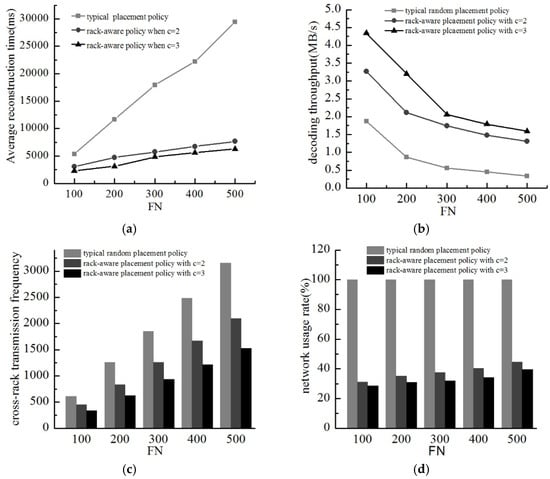
Figure 6.
Data reconstruction performance of three different placement methods. (a) Average reconstruction time; (b) Decoding throughput; (c) Cross-rack transmission frequency; (d) Network usage.
Figure 6a shows the average reconstruction time of the three different data layout schemes. The average reconstruction time increases with an increase in the number of files. With the same number of files, the data reconstruction time of the rack aware placement policy is less than the typical single block per rack layout scheme. Besides, when c = 3, the new policy uses less time than when c = 2.
Figure 6b shows the decoding throughput decreases with an increase in the number of files. Under the same conditions, the decoding throughput of the new scheme is higher than the typical layout scheme, and within the new scheme, the decoding throughput of c = 3 is higher than that of c = 2.
Figure 6c gives the cross-rack transmission frequency of the three different data layout schemes during the data reconstruction process. The cross-rack transmission frequency of different layout scheme has the same tendency with the number of files. Additionally, the rack aware placement policy costs less cross-rack transmission time than the typical scheme, and the new scheme has better performance with a larger c.
Figure 6d shows the network usage of three different data layout schemes in the process of data reconstruction. When FN changes from 100–500, the typical layout scheme always exhausts the entire network resources. In the new scheme, network occupancy rate increases with an increase in the number of documents but never more than 50%. The new scheme has lower network usage when c = 3 than c = 2.
Above all, the rack aware placement policy does a better job compared with the typical deployment policy. Meanwhile, a larger c in the new scheme gets better performance in the four analyzed ways (network usage, cross-rack transmission frequency, data reconstruction execution time, and encoding throughput). This demonstrates the fact that fewer racks for deploying encoded blocks makes fewer cross-rack traffic. Network usage reduces as much as 50%. Thus, the rack aware scheme effectively obtains the goal to simultaneously reduce the cross-rack transmission times and transmission volume. That is to say, the new scheme relieves the competition for the core network and improve data reconstruction efficiency with less decoding time.
4.2.2. Load Balancing Performance
There must also be a performance test for the load balancing algorithm. We performed some experiments with two load-balancing algorithms—random (without load balancing) and the proposed load-balancing algorithm. The test parameters are set as in the previous case, but the file size is changed to 100 MB. Additionally, we set a very limited available network bandwidth. The experimental results are shown in Figure 7 for each set of data in the previous diagram based on the multiple tests.
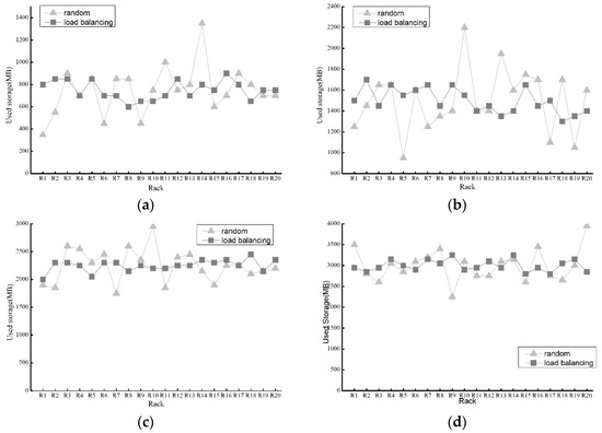
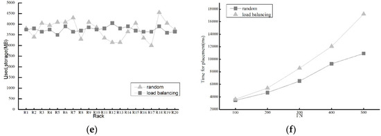
Figure 7.
Storage load of two kinds of load balancing methods. (a) Storage usage when FN = 100; (b) Storage usage when FN = 200; (c) Storage usage when FN = 300; (d) Storage usage when FN = 400; (e) Storage usage when FN = 500; (f) Average deploying time with variable FN.
Figure 7a–e shows the used storage of the two algorithms with FN ranging from 100 to 500. Although the random method can keep balance to a certain extent, our method has better advantages in load balancing of storage. Applying our load balancing algorithm, each rack has approximately storage usage unlike the random as FN gets larger. Therefore, it is evident that our load balancing algorithm achieves good performance in terms of storage load balancing.
In Figure 7f, with limited bandwidth, the deploying time using the random algorithm is very close to using our load balancing algorithm at the beginning. As FN increases, the time of the random algorithm increases very fast, while that of the load balancing algorithm grows slowly. One important reason is that the amount of time spent for waiting on limited network bandwidth, thereby our algorithm effectively avoids such network congestion. Thus, our method can partly balance network load partly.
To sum up, in our rack aware data placement method, the load balancing algorithm plays a vital role in load balancing of the network and storage.
4.2.3. Reconstruction Performance for Comparison
We also compare our placement method with the traditional Reed-Solomon-based reconstruction technique (Traditional RS) and CAR [4] in terms of average reconstruction time and cross-rack traffic. With the same parameters as those in Section 4.2.1, we evaluate their average reconstruction time and cross-rack traffic. The experimental results are shown in Figure 8.
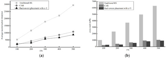
Figure 8.
Performance evaluations of Traditional RS, CAR and our Rack-aware placement with c=3. (a) Average reconstruction time; (b) Cross-rack transmission frequency.
Figure 8a shows that the rack aware data placement method and CAR observably reduce average reconstruction time. The reconstruction time of the rack aware data placement is very close to that of CAR. The same status of three method is also true for cross-rack traffic and our method greatly reduce cross-rack transmission.
In short, it is evident that our method does a good job in reconstruction time and cross-rack traffic reduction compared with traditional RS and CAR.
5. Conclusions and Future Work
Reducing network traffic is an important way to improve the efficiency of data reconstruction in erasure-coded clustered storage systems. Because of high cross-rack transmission consumption and low data reconstruction efficiency in the typical layout scheme, a rack-aware data placement strategy has been proposed. To take into account an encoded block layout that can effectively reduce the cross-rack transmission before decoding, encoded blocks are placed as uniformly random as possible. Through theoretical analysis and simulation experiments, the new method reduces cross-rack data transmission frequency and transmission volume as well as ensuring data availability without any additional storage. At the same time, our method also keeps storage and network balance with a load balancing algorithm which considers available bandwidth and available storage space.
In future work, there are two main areas of consideration: considering the future workloads to optimize the layout of data and undertaking further experimental investigations.
Author Contributions
D.S. designed the algorithms and wrote the paper. B.S., G.B. and Y.Z. made a careful revision of the article and proposed amendments.
Acknowledgments
This work was supported by the National Natural Science Foundation of China under Grant No. 61672416.
Conflicts of Interest
The authors declare no conflict of interest.
References
- Wang, Y.; Xu, F.; Pei, X. Research on Erasure Code-Based Fault-Tolerant Technology for Distributed Storage. Chin. J. Comput. 2017, 40, 236–255. [Google Scholar]
- Li, R.; Hu, Y.; Lee, P.P.C. Enabling Efficient and Reliable Transition from Replication to Erasure Coding for Clustered File Systems. In Proceedings of the 45th Annual IEEE/IFIP on Dependable Systems and Networks, Rio de Janeiro, Brazil, 22–25 June 2015; pp. 148–159. [Google Scholar]
- Hu, Y.; Lee, P.P.C.; Zhang, X. Double Regenerating Codes for Hierarchical Data Centers. In Proceedings of the IEEE International Symposium on Information Theory, Barcelona, Spain, 10–15 July 2016; pp. 245–249. [Google Scholar]
- Shen, Z.; Lee, P.P.C.; Shu, J.; Guo, W. Cross-Rack-Aware Single Failure Recovery for Clustered File Systems. IEEE Trans. Dependable Secure Comput. 2017, 99, 1. [Google Scholar] [CrossRef]
- Yin, C.; Wang, J.; Lv, H.; Cui, Z.; Cheng, L.; Li, T.; Liu, Y. BDCode: An erasure code algorithm for big data storage systems. J. Univ. Sci. Technol. China 2016, 46, 188–199. [Google Scholar]
- Li, R.; Lee, P.P.C.; Hu, Y. Degraded-First Scheduling for Mapreduce in Erasure-Coded Storage Clusters. In Proceedings of the 44th Annual IEEE/IFIP on Dependable Systems and Networks, Atlanta, GA, USA, 23–26 June 2014; pp. 419–430. [Google Scholar]
- Li, R.; Li, X.; Lee, P.P.C.; Huang, Q. Repair Pipelining for Erasure-Coded Storage. In Proceedings of the 2017 USENIX Annual Technical Conference (USENIX ATC’17), Santa Clara, CA, USA, 12–14 July 2017; pp. 567–579. [Google Scholar]
- Ahn, H.Y.; Lee, K.H.; Lee, Y.J. Dynamic erasure coding decision for modern block-oriented distributed storage systems. J. Supercomput. 2016, 72, 1312–1341. [Google Scholar] [CrossRef]
- Chowdhury, M.; Kandula, S.; Stoica, I. Leveraging endpoint flexibility in data-intensive clusters. ACM SIGCOMM Comput. Commun. Rev. 2013, 43, 231–242. [Google Scholar] [CrossRef]
- Albano, M.; Chessa, S. Replication vs erasure coding in data centric storage for wireless sensor networks. Comput. Netw. 2015, 77, 42–55. [Google Scholar] [CrossRef]
- Huang, X.; Li, H.; Zhang, Y.; Hou, H.; Zhou, T.; Guo, H.; Zhang, H. Study on Binary Regenerating Codes for Big Data Storage Systems. J. Comput. Res. Dev. 2013, 50, 54–63. [Google Scholar]
- Chen, L.; Hang, J.; Teng, P.; Wang, X. Random Binary Extensive Code (RBEC): An Efficient Code for Distributed Storage System. Chin. J. Comput. 2017, 40, 1980–1995. [Google Scholar]
- Ge, J.; Chen, Z.; Fang, Y. Erasure codes-based data placement fault-tolerant algorithm. Appl. Res. Comput. 2014, 31, 2688–2691. [Google Scholar]
- Wu, Y.; Dimakis, A.G.; Ramchandran, K. Deterministic Regenerating Codes for Distributed Storage. In Proceedings of the Allerton Conference on Communication, Control, and Computing 2007, Monticello, IL, USA, 26–28 September 2007. [Google Scholar]
- Wu, Y.; Dimakis, A.G. Reducing Repair Traffic for Erasure Coding-Based Storage via Interference Alignment. In Proceedings of the IEEE International Conference on Symposium on Information Theory, Seoul, South Korea, 28 June–3 July 2009; pp. 2276–2280. [Google Scholar]
- Cullina, D.; Dimakis, A.G.; Ho, T. Searching for Minimum Storage Regenerating Codes. In Proceedings of the Allerton Conference on Communication, Control, and Computing 2009, Monticello, IL, USA, 30 September–2 October 2009. [Google Scholar]
- Dimakis, A.G.; Godfrey, P.B.; Wu, Y.; Wainwright, M.J.; Ramchandran, K. Network Coding for Distributed Storage Systems. IEEE Trans. Inf. Theory 2010, 56, 4539–4551. [Google Scholar] [CrossRef]
- Dimakis, A.G.; Ramchandran, K.; Wu, Y.; Suh, C. A Survey on Network Codes for Distributed Storage. Proc. IEEE 2011, 99, 476–489. [Google Scholar] [CrossRef]
- Hou, H.; Lee, P.P.C.; Shum, K.W.; Hu, Y. Rack-Aware Regenerating Codes for Data Centers. arXiv 2018, arXiv:1802.04031. [Google Scholar]
- Ma, Y.; Nandagopal, T.; Puttaswamy, K.P.N.; Banerjee, S. An Ensemble of Replication and Erasure Codes for Cloud File Systems. In Proceedings of the 32nd IEEE International Conference on Computer Communications, Turin, Italy, 14–19 April 2013; pp. 1276–1284. [Google Scholar]
- Zheng, Z.; Meng, H.; Li, D.; Wang, Z. Research on dynamic replication redundancy storage strategy based on erasure code. Comput. Eng. Des. 2014, 35, 3085–3090. [Google Scholar]
- Li, X.; Dai, X.; Li, W.; Cui, Z. Improved HDFS scheme based on erasure code and dynamical-replication system. J. Comput. Appl. 2012, 32, 2150–2153. [Google Scholar] [CrossRef]
- Yang, D.; Wang, Y.; Liu, P. Fault-tolerant mechanism combined with replication and error correcting code for cloud file systems. J. Tsinghua Univ. 2014, 54, 137–144. [Google Scholar]
- Gribaudo, M.; Iacono, M.; Manini, D. Improving reliability and performances in large scale distributed applications with erasure codes and replication. Future Gener. Comput. Syst. 2016, 56, 773–782. [Google Scholar] [CrossRef]
- Silberstein, M.; Ganesh, L.; Wang, Y.; Alvisi, L.; Dahlin, M. Lazy Means Smart: Reducing Repair Bandwidth Costs in Erasure-Coded Distributed Storage. In Proceedings of the International Conference on Systems and Storage, Haifa, Israel, 30 June–2 July 2014; ACM: New York, NY, USA, 2014; pp. 1–7. [Google Scholar]
- Huang, C.; Simitci, H.; Xu, Y.; Ogus, A.; Calder, B.; Gopalan, P.; Li, J.; Yekhanin, S. Erasure Coding in Windows Azure Storage. In Proceedings of the USENIX Annual Technical Conference, Boston, MA, USA, 13–15 June 2012; pp. 15–26. [Google Scholar]
- Sathiamoorthy, M.; Asteris, M.; Papailiopoulos, D.; Dimakis, A.G.; Dimakis, R.; Dimakis, S. Xoring Elephants: Novel Erasure Codes for Big Data. In Proceedings of the VLDB Endowment, Trento, Italy, 26–30 August 2013; pp. 325–336. [Google Scholar]
- Rashmi, K.V.; Nakkiran, P.; Wang, J.; Shah, N.B.; Ramchandran, K. Having Your Cake and Eating It Too: Jointly Optimal Erasure Codes for I/O, Storage, and Network-bandwidth. In Proceedings of the 13th USENIX Conference on File and Storage Technologies, Santa Clara, CA, USA, 16–19 February 2015; pp. 81–94. [Google Scholar]
- Rashmi, K.V.; Shah, N.B.; Gu, D.; Kuang, H.; Borthakur, D.; Ramchandran, K. A Hitchhiker’s Guide to Fast and Efficient Data Reconstruction in Erasure-Coded Data Centers. In Proceedings of the 2014 ACM conference on SIGCOMM, Chicago, IL, USA, 17–22 August 2014; pp. 331–342. [Google Scholar]
- Muralidhar, S.; Lloyd, W.; Roy, S.; Hill, C.; Lin, E.; Liu, W.; Pan, S.; Shankar, S.; Tang, L.; Kumar, S. F4: Facebook’s Warm Blob Storage System. In Proceedings of the 11th USENIX conference on Operating Systems Design and Implementation, Broomfield, CO, USA, 6–8 October 2014; pp. 383–398. [Google Scholar]
- Zhu, L.; Wang, R.; Yang, H. Multi-path Data Distribution Mechanism Based on RPL for Energy Consumption and Time Delay. Information 2017, 8, 124. [Google Scholar] [CrossRef]
- Ferdaus, M.H.; Murshed, M.; Calheiros, R.N.; Buyyab, R. An algorithm for network and data-aware placement of multi-tier applications in cloud data centers. J. Netw. Comput. Appl. 2017, 98, 65–83. [Google Scholar] [CrossRef]
- Mitra, S.; Panta, R.; Ra, M.R.; Bagchi, S. Partial-Parallel-Repair (PPR): A Distributed Technique for Repairing Erasure Coded Storage. In Proceedings of the Eleventh European Conference on Computer Systems, London, UK, 18–21 April 2016; ACM: New York, NY, USA, 2016. [Google Scholar]
- Ford, D.; Labelle, F.; Popovici, F.I.; Stokely, M.; Truong, V.; Barroso, L.; Grimes, C.; Quinlan, S. Availability in Globally Distributed Storage Systems. In Proceedings of the 9th USENIX Symposium on Operating Systems Design and Implementation, Vancouver, BC, Canada, 4–6 October 2010; pp. 1–7. [Google Scholar]
- Gastón, B.; Pujol, J.; Villanueva, M. A Realistic Distributed Storage System that Minimizes Data Storage and Repair Bandwidth. In Proceedings of the Data Compression Conference, Snowbird, UT, USA, 20–22 April 2013; p. 491. [Google Scholar]
- Ahmad, F.; Chakradhar, S.T.; Raghunathan, A.; Vijaykumar, T.N. ShuffleWatcher: Shuffle-Aware Scheduling in Multi-Tenant MapReduce Clusters. In Proceedings of the USENIX Annual Technical Conference 2014, Philadelphia, PA, USA, 19–20 June 2014; pp. 1–12. [Google Scholar]
- Li, J.; Yang, S.; Wang, X.; Li, B. Tree-Structured Data Regeneration in Distributed Storage Systems with Regenerating Codes. In Proceedings of the IEEE INFOCOM, San Diego, CA, USA, 15–19 March 2010; pp. 1–9. [Google Scholar]
© 2018 by the authors. Licensee MDPI, Basel, Switzerland. This article is an open access article distributed under the terms and conditions of the Creative Commons Attribution (CC BY) license (http://creativecommons.org/licenses/by/4.0/).