Abstract
Pneumatic linear peristaltic actuators present several potential advantages over conventional ones such as low cost, virtually unlimited stroke, and an easy implementation of curved motion profiles. However, the body of this type of actuators also suffers from high mechanical stress, leading to a decrease in the hose wall thickness, which leads to increased leakages between chambers. One way to potentially minimize this problem is to impose the force instead of the displacement between rollers. This paper describes the model and experimental characteristics of a new prototype of a linear pneumatic peristaltic actuator where either the force or the displacement between rollers can be imposed. Namely, experimental friction characteristics and the leakage between chambers are determined in the configuration where the force between rollers is imposed. Lastly, a third-order linear model is experimentally identified. Therefore, this study establishes the basis for future research focused on the service life and leakage obtained whenever the force between rollers is imposed.
1. Introduction
Pneumatic systems have always been attractive for industrial environments due to their low cost, high power to weight ratio, and high velocity. Nevertheless, pneumatic actuation solutions are often discarded as they present some disadvantageous characteristics.
One of such characteristics is the complexity associated with the fine motion control of conventional pneumatic actuators. Several concurrent factors cause this complexity, namely the high compliance of pneumatic solutions, the nonlinear behavior of servo valves, and the nonlinear and uncertain behavior of friction forces in rod and piston seals.
The above-described nonlinear behavior leads to the need of complex, model-dependent, and highly active control laws to cope with the underlying uncertainty [1,2,3]. As a consequence, accurate motion control can be achieved, but the price to pay is motion smoothness.
When compared to servo electromechanical alternatives, the energy efficiency of pneumatic systems is claimed to be low [4,5,6]. For instance, in [6], an assessment of the energetic efficiency of a typical pneumatic solution is made. That study shows that even accounting for an ideal compressor and motor, and disregarding friction effects on the actuator, the pneumatic solution efficiency was below 28%. Nevertheless, it should be underlined that there is still some disagreement in the literature as to which is the best solution (pneumatic or electric) for a given application. For example, in [7], some applications are presented where pneumatic solutions perform better than their electrical counterparts, if the right criteria for the design of the servopneumatic device are chosen.
A novel idea that has recently been presented in [8] is the use of a deformable piston structure covered by a flexible membrane: the so-called tension piston. Significant energy improvements are claimed in [8], as the configuration allows pneumatic energy to be converted into mechanical energy using two different ways: pressure on the piston rigid areas and a pneumatic-induced tension on the piston flexible membrane. This configuration presents some potential advantages over conventional techniques. Since a flexible membrane is used for sealing, it has no leakages and exhibits low friction forces, making it potentially more appealing for servo control. In addition, in [8], it is shown that the tension piston can develop higher forces when compared to a conventional piston at the same pressure. Although the authors of [8] sustain that this leads to substantially higher power and energy efficiency, the conventional actuator used for comparison in [8] uses conventional seals. This means that the datum cylinder presents high friction forces that apparently were not accounted for in some of the comparisons made in [8]. Some drawbacks are as follows: (i) the configuration potentially leads to lower endurance, as it involves a flexible membrane, (ii) it presents a nonlinear force dependence with the piston position, and (iii) it requires a higher actuator length for the same stroke when compared to conventional actuators. Flexible materials are also used in pneumatic muscles [9,10], which are an alternative to conventional pneumatic cylinders whenever a high power-to-weight ratio is a primary requisite.
In [11,12], the authors of this study also used flexible membranes to devise a pneumatic linear peristaltic actuator (PLPA). It is made up of a hose compressed by two rollers that act as a piston. Several advantages can be identified in comparison with conventional actuators: it is a potentially low weight and cost actuator, it has a virtually unlimited stroke, and it can easily perform curved motion profiles. Potential applications are machines used for pick and place tasks found in many industry sectors such as for instance the packaging industry.
In addition, as presented in [11,12], the friction characteristics of a PLPA are more beneficial than its conventional counterparts, making the task of devising control laws significantly less complex. In fact, the simple use of a PID-type controller led to zero steady-state error in [12], whilst the use of similar controllers with conventional low friction actuators can lead to limit cycles [12].
One of the drawbacks of a PLPA lies in the fact that the body of the actuator is subject to high mechanical stress, given the need to compress the hose between the rollers to achieve low leakages between chambers. The main causes of failure of such actuators were determined in [13] by experimentally characterizing some of the mechanical properties of three different types of hoses. Those hoses were used in experimental durability tests to determine the failure causes and to determine the influence of different parameters in the longevity of the actuator. As for the main results, it was found that conventional gardening hoses covered a distance of around two orders of magnitude lower than the typical distance covered by pneumatic cylinders. Consequently, further research is required to devise new types of hoses materials and shapes. Another interesting conclusion of [13] is that the thickness of the hose walls can be significantly reduced during operation. In [11,12,13], the distance between rollers is fixed so that the inter-chamber leakage increases due to this effect.
The present paper builds upon previous studies [11,12,13] by presenting a new PLPA prototype where the force between rollers is imposed, so that the thickness reduction previously described becomes compensated. Furthermore, the new experimental setup is fully characterized in terms of inter-chamber leakages and friction. A linear model of the system is experimentally identified and motion control results with a PID type controller are presented.
2. Experimental Setup
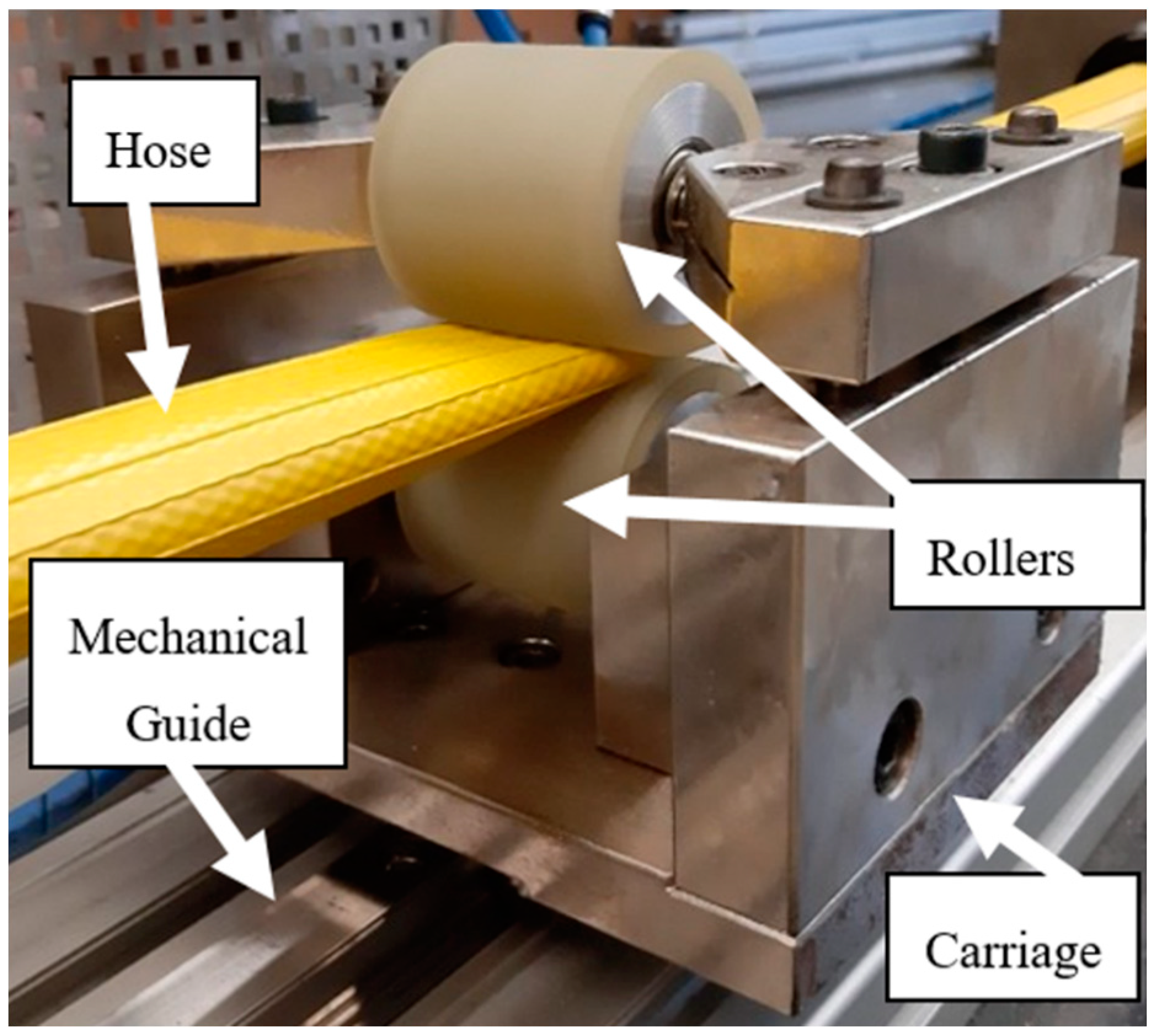
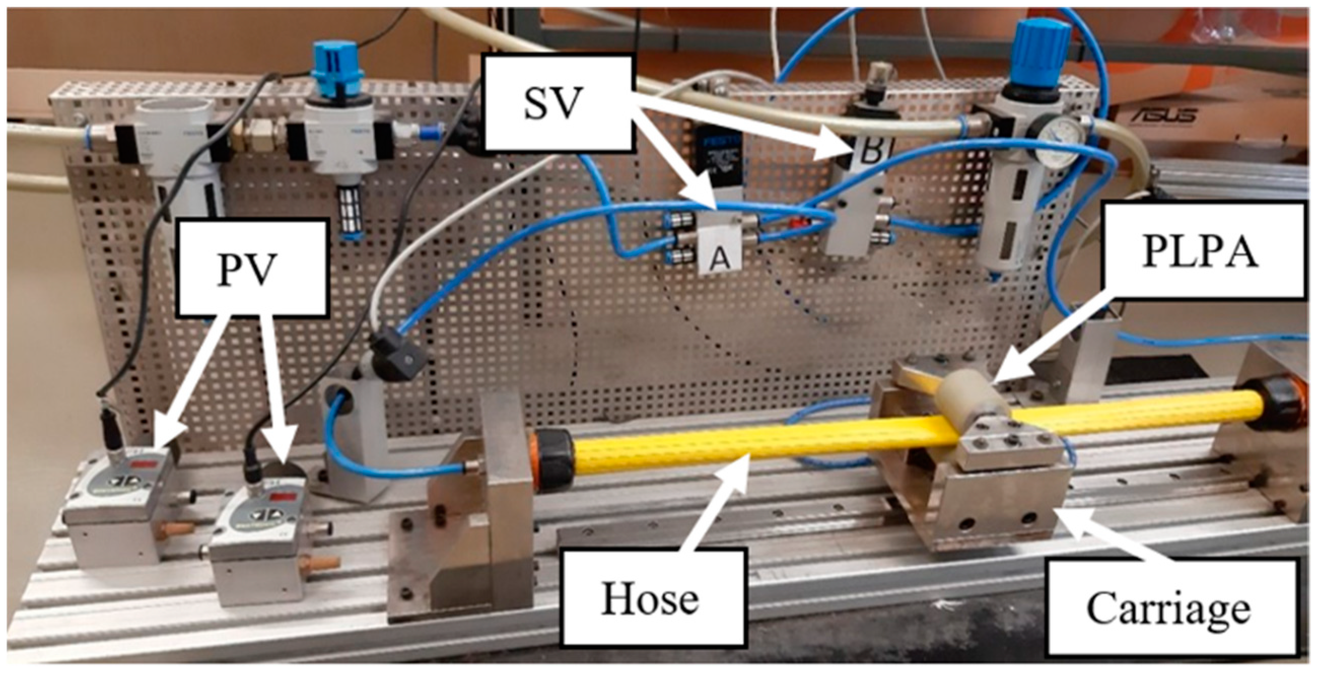
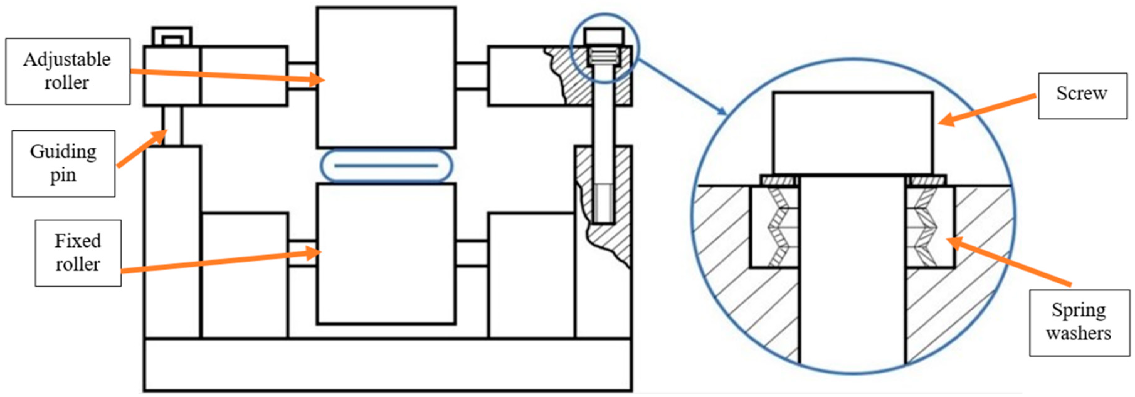
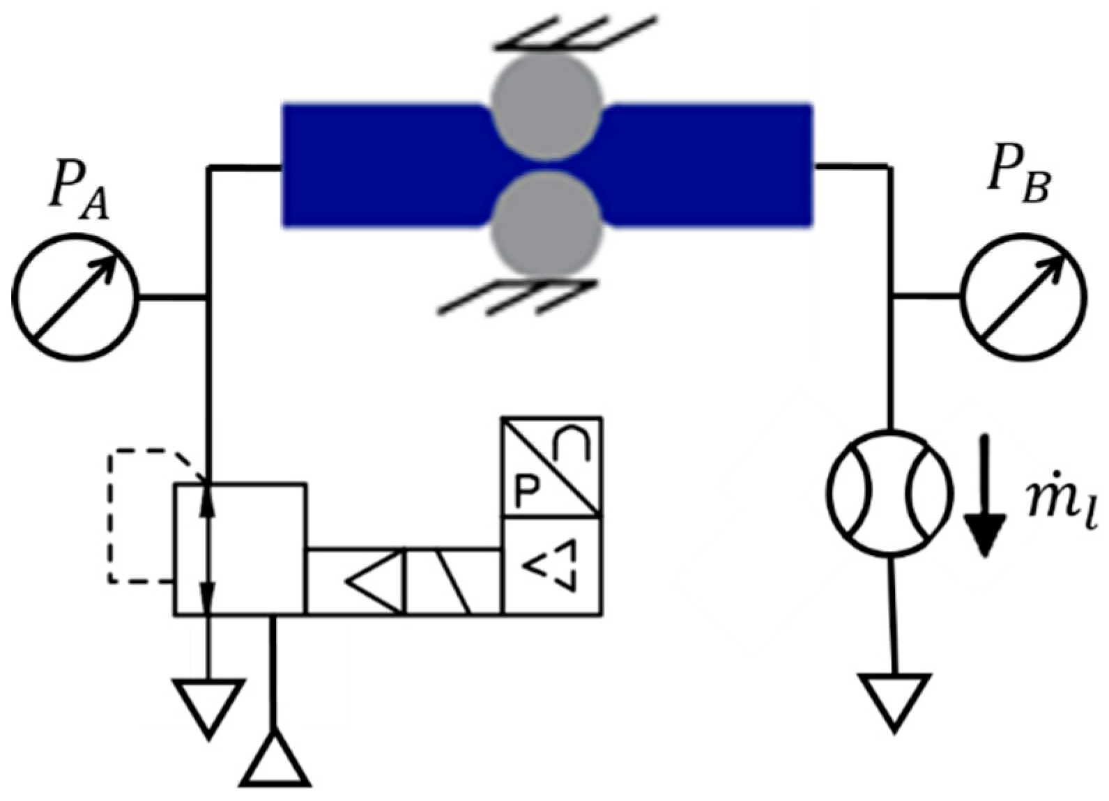
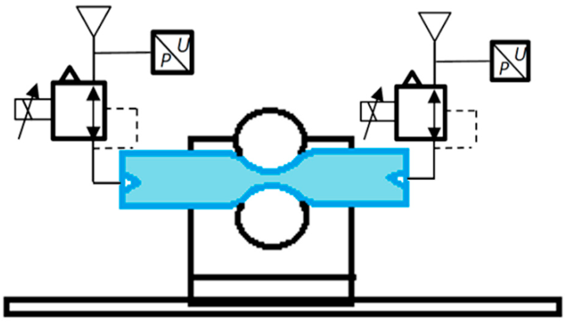
2.1. Overall Description
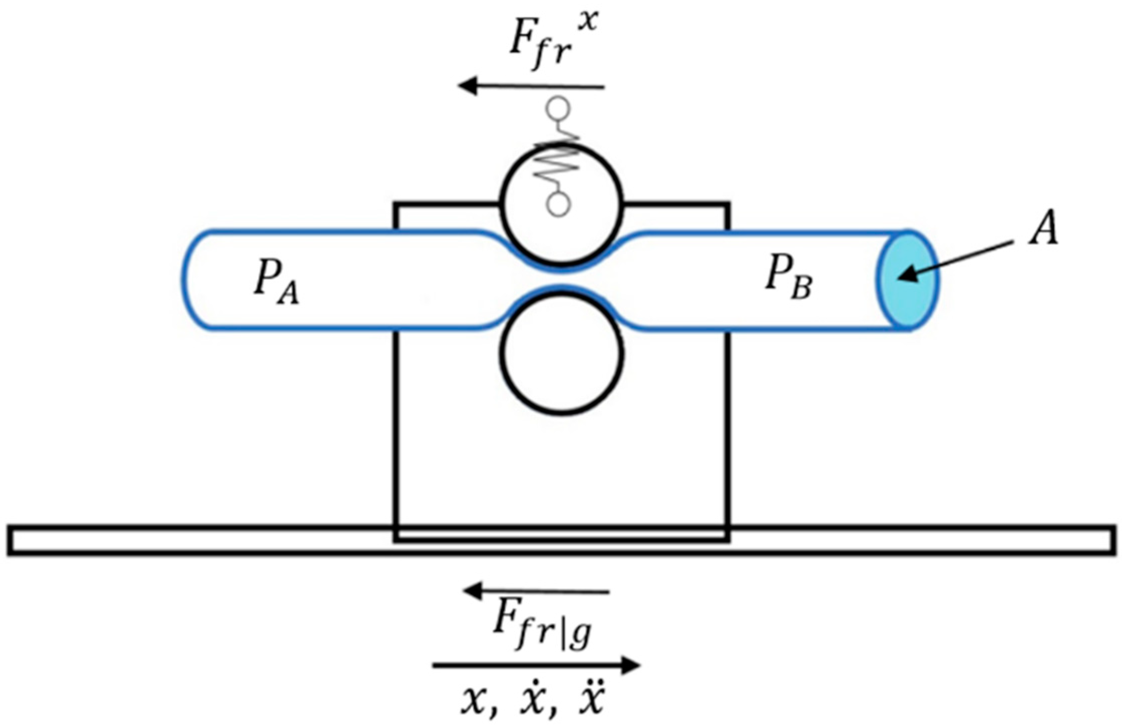
The linear peristaltic actuator considered in this work is depicted in Figure 1: compressed air is fed to one end of a hose, which is divided into two chambers by two rollers pressed against it. The pressure difference between chambers caused by compressed air creates a force () acting on the rollers. This force contains a vertical component () which is absorbed by the roller supports and a horizontal component () that drives the rollers. A mechanical guide connected to the rollers absorbs the forces and torques acting on the system. In the motion direction, friction is exclusively due to the ball bearings (). Sliding friction arises in the transversal direction () due to the hose cross-section change [12]. However, since this direction is mostly orthogonal to the motion direction, it is expected that this sliding friction has an insignificant impact on the rollers’ motion. Figure 2 presents a diagram of the forces acting on the system.
Figure 1.
Pneumatic linear peristaltic actuator.
Figure 2.
Forces acting in the pneumatic linear peristaltic actuator (PLPA): (a) lateral view and (b) top view.
The complete experimental setup used in this work is shown in Figure 3 and includes a PLPA mounted on a carriage, running over a Bosch Rexroth guidance system (IMS series). Based on the results obtained in [13] regarding the longevity of the PLPA, several modifications to the original setup were made in an attempt to increase its service life: first, the two aluminum rollers on the PLPA have a urethane coating to reduce the stress in the hose. In this setup, the bottom roller is fixed to the carriage and the top one’s height is adjustable with the help of two screws on each side. If a set of four spring washers on each of these screws is used, the force between the rollers can be imposed. A drawing of the carriage with the spring washers is shown in Figure 4. In addition, the hose chosen for this study was FLEXIGOM AIR, manufactured by Productos Mesa (Santo Domingo de la Calzada, Spain), which was the most durable hose tested in [13]. This hose, designed for use with compressed air at a 30 bar maximum working pressure, comprises a flexible nitrile rubber sleeve reinforced with a high tenacity polyester fabric and an abrasion-resistant external coating. In addition, the setup includes two FESTO servo valves (SV) and two proportional pressure-reducing valves (PV), which allow flow/pressure control of the compressed air in each chamber, respectively. These valves are connected to the PLPA in different ways, according to the test to be carried out.
Figure 3.
Experimental setup.
Figure 4.
Carriage schematic.
The pressure inside each chamber is measured with two pressure transducers (0–10 bar range) with an accuracy of 0.2% of the full-scale value. The position of the carriage is measured with a position encoder having a 5 μm resolution, ±0.75 μm interpolation accuracy, and ±0.25 μm repeatability. All equipment are connected to a data acquisition and control system including a PC with data acquisition boards and all the necessary signal conditioning hardware.
2.2. System Model
Applying Newton’s second law to the moving elements (please see Figure 2 and Figure 5) leads to:
where represents the moving mass, , , and are its position, velocity, and acceleration, respectively, and is the friction between the carriage and the monorail guide.
Figure 5.
Mechanical model nomenclature.
As detailed in [11], the pneumatic force in the horizontal direction is:
where represents the pressure acting inside the PLPA chambers A and B, respectively, represents the hose cross-section area, is the sliding friction in the transversal direction, and is a factor relating the hose flattening velocity in the transversal direction () to the moving mass velocity in the horizontal direction (). The total friction force acting on the PLPA () is:
On the other hand, the friction force can be divided into viscous and static friction, as presented in [14]:
In this equation, is the viscous friction coefficient and is the nonlinear static friction force.
Under the typical condition that the pressure inside each one of the PLPA chambers is higher than 0.2 bar, the hose’s cross-section can be considered constant [9]. Consequently, the roller motion caused by the pressure difference is the only responsible for the volume change inside each chamber. Under these circumstances and considering that temperature fluctuations over the equilibrium temperature are negligible, the pressure dynamics of chambers A and B are given by [15]:
where represents each chamber’s volume, is the ratio of specific heats for air, is the ambient temperature and , represent the mass flow of air entering and leaving each chamber, respectively. In order to determine the mass flow of air , a balance should be performed between (i) the flow retrieved or delivered by the servo or pressure-reducing valves [16,17,18] and (ii) the leakage flow . However, in the present work, the leakage between chambers is negligible (please see Section 3.1).
The working port of each servo valve is connected to each of the PLPA chambers.
According to the ISO 6358 standard [19], the flow in a restriction can be determined by
with
where , are the pressure and temperature upstream of restriction i, is the downstream pressure, is the sonic conductance of the restriction, is the density in reference conditions [16], and the experimental critical pressure ratio. By applying Equations (6) and (7) to both restrictions of the servo valve [14], the model for the mass flow of each working port can be obtained (please see the details in [16]):
As can be seen, the model defined in Equations (1) to (8) is nonlinear. By following a similar procedure to the one presented in [14], the following third-order linearized model can be written:
where are the equilibrium constants, is the harmonic mean of the pressure time constants of the PLPA, is the constant of air as a perfect gas, and are the flow gain values for each of the servo-valve working ports. It should be noted that in equilibrium conditions, . Since the controller considered in Section 4 is linear, the identification of the system linearized model will be performed in the next section.
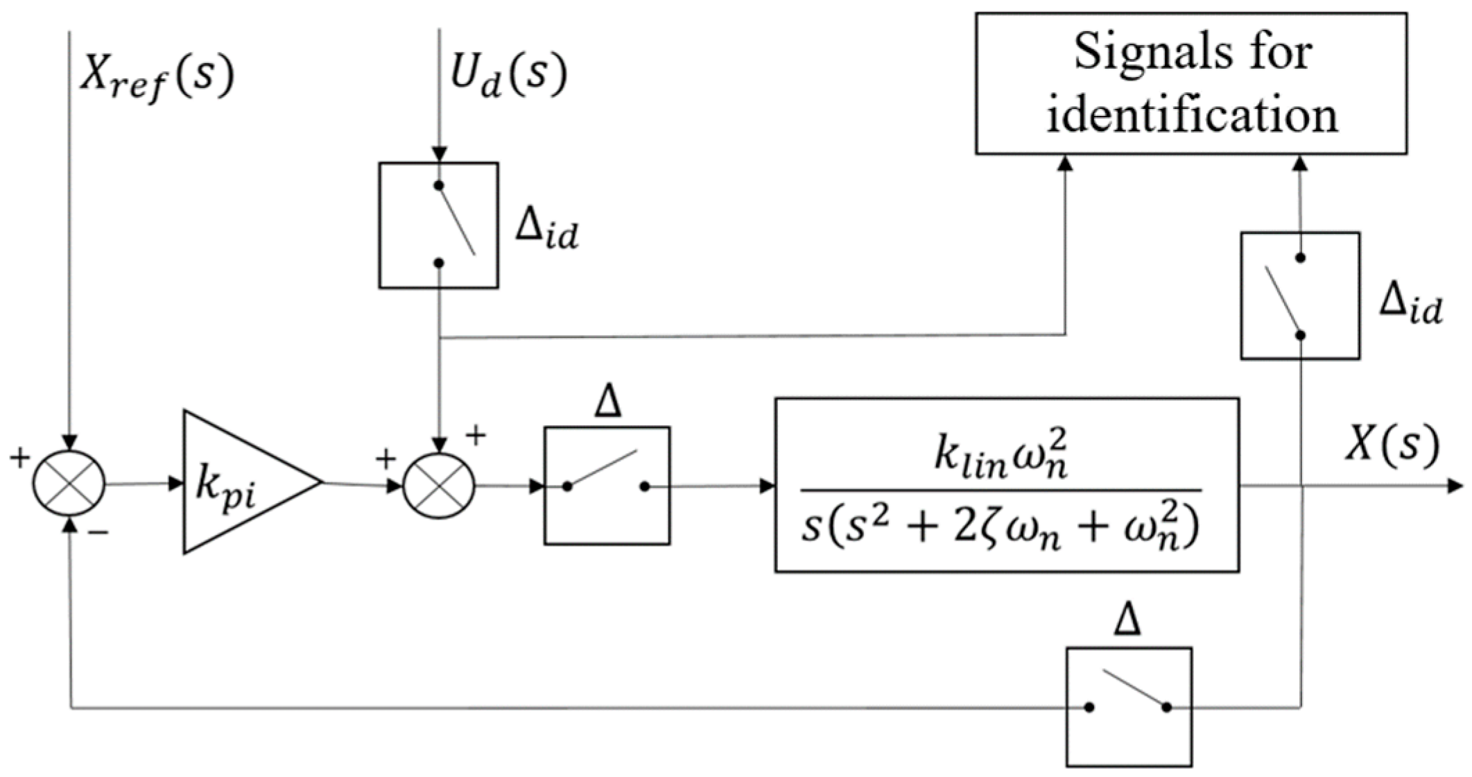
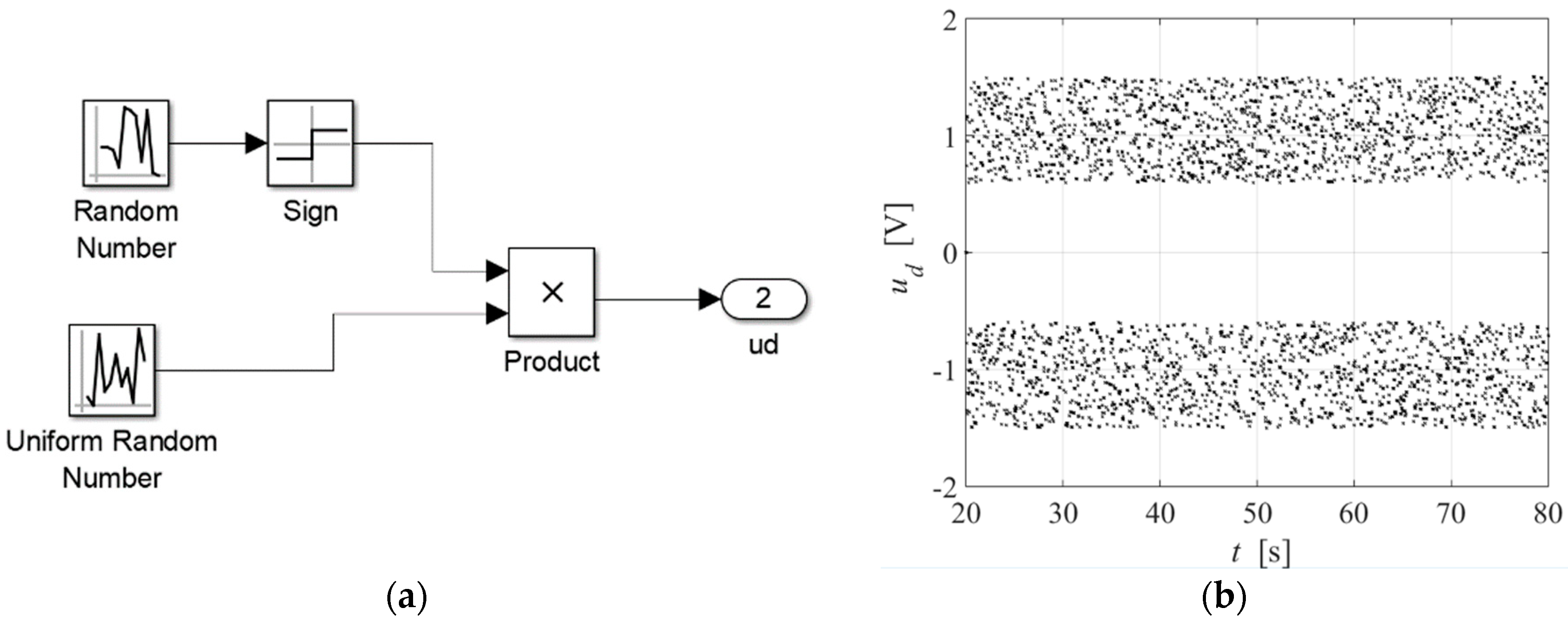
2.3. System Identification
Since some controller designs require a linear model of the system, the experimental identification of the system was performed. Using Equation (9), the third-order linear model can also be described by the following transfer function, where s represents the Laplace variable:
where
The parameters in Equation (10) were determined based on experimental data by using Matlab®’s System Identification Toolbox. The data acquisition and control were run with a sampling time () substantially lower than the sampling time used for identification (. This ensures that from an identification’s point of view, the system behaves as being essentially continuous.
Since this is a Type 1 system, the PLPA could hit the stroke ends during the identification procedure. To circumvent this, a proportional controller was used to attract the PLPA to the middle of the stroke. Persistent excitation is ensured by a disturbance signal added to the control action, as presented in Figure 6.
Figure 6.
Schematic of the identification.
Using this approach, two transfer functions exist: one between and , and another between and . However, only the latter contains the system dynamic information, since the signal is constant. The transfer function considered for identification was thus:
The disturbance signal is presented in Figure 7 and its parameters are shown in Table 1. The system parameters identified with this procedure are shown in Table 2.
Figure 7.
Disturbance signal for identification: (a) signal implementation; (b) signal output.
Table 1.
Identification signal parameters.
Table 2.
Identified system parameters.
3. Experimental Characterization
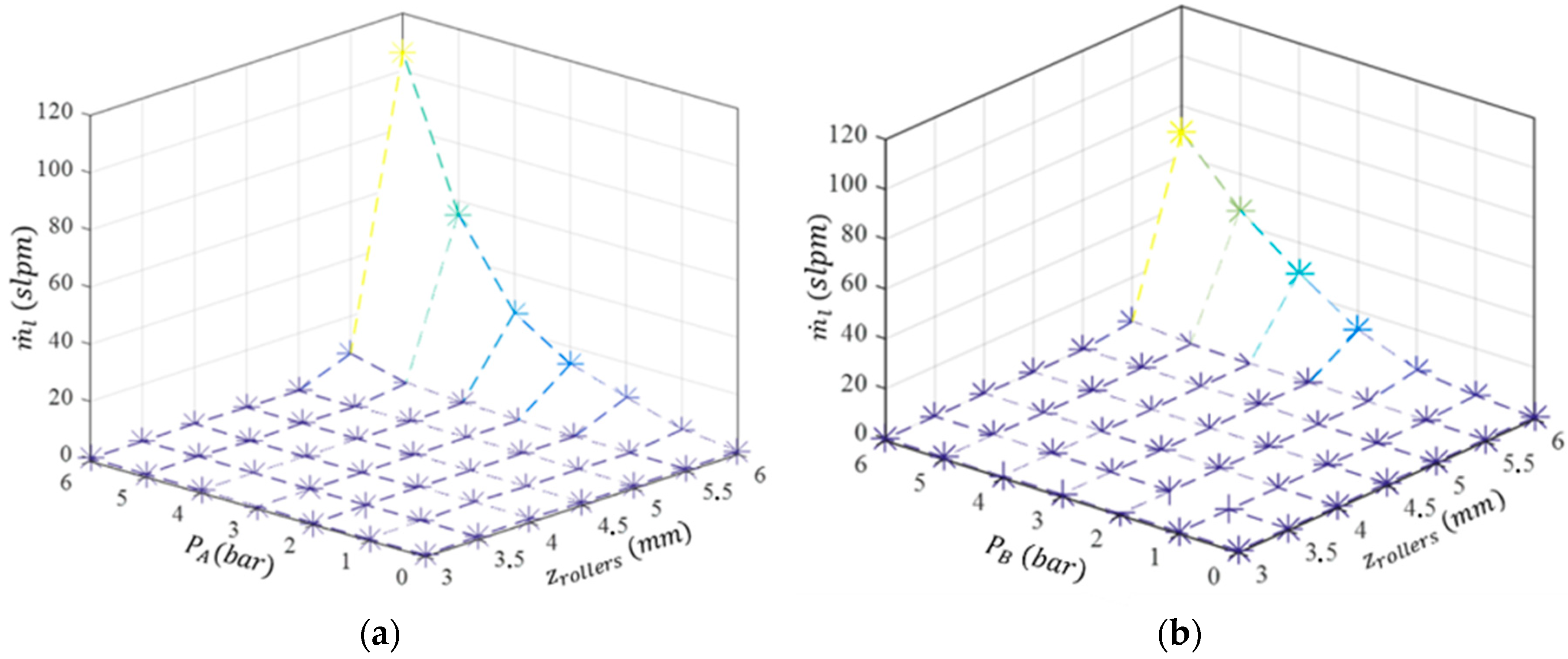
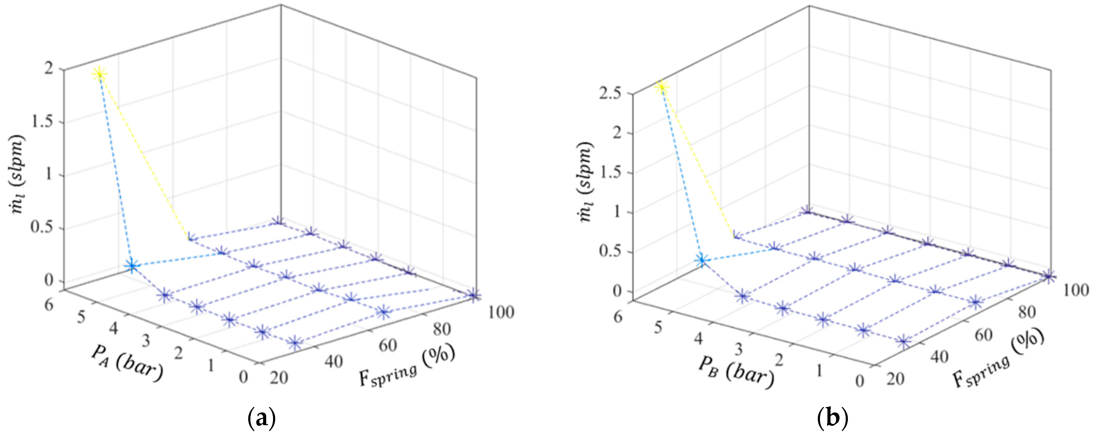
3.1. Leakage Measurements
In order to measure the leakage flow between chambers and through the pneumatic fittings, , the scheme shown in Figure 8 was used.
Figure 8.
Experimental setup for leakage measurements.
The carriage was mechanically blocked and while one chamber was pressurized, the other was left open. Leakage measurements were performed in chambers A and B for different distance and force adjustments between rollers. For experiments with a fixed distance adjustment (), was determined for distance values from 3 to 6 mm using a 0.5-mm step. For experiments with force adjustment, spring force values () of 33%, 66%, and 100% of the maximum spring force were tested. In both kinds of experiments, the pressure was increased from 0 to 6 bar with a 1-bar step. The leakage measurement results for distance and force adjustments are presented in Figure 9 and Figure 10, respectively.
Figure 9.
Leakage measurements with roller distance adjustment: (a) chamber A; (b) chamber B.
Figure 10.
Leakage measurements with force adjustment: (a) chamber A; (b) chamber B.
Regarding Figure 10, it can be seen that up to 5 bar, as long as the spring force is greater than 33% of , the leakage is essentially zero. In addition, if is bigger than 66% of , there is not essentially any leakage, regardless of the input pressure. Since it is expected that an imposed force between rollers might contribute to extend the service time of the actuator, the results presented in the following sections will be based on that adjustment.
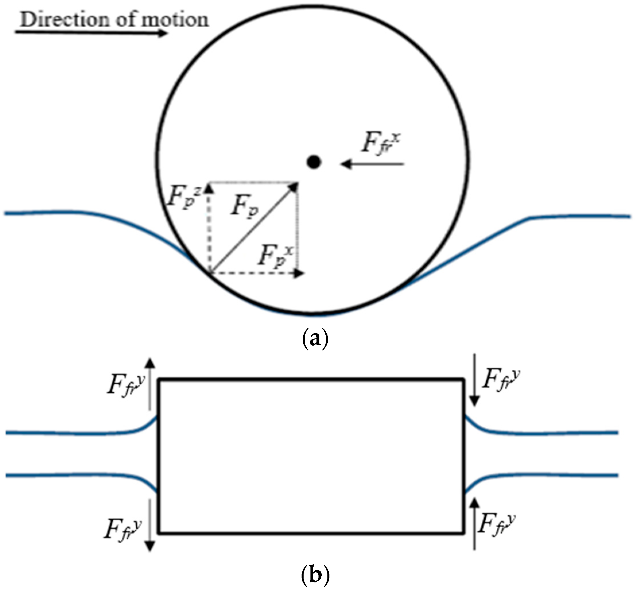
3.2. Friction Measurements
In this section, the system friction along the motion direction (PLPA and the mechanical guide) is experimentally characterized. Static and dynamic experiments were conducted. The first ones determine the necessary breakaway force to initiate motion while the second ones, made at constant velocity, determine viscous friction. When the PLPA is stationary or it moves at constant velocity, the acceleration in Equation (1) is zero. Then, the friction forces acting on the setup () can be determined by combining Equations (1) and (3):
The next sections provide a detailed description of the conducted friction experiments and the results obtained.
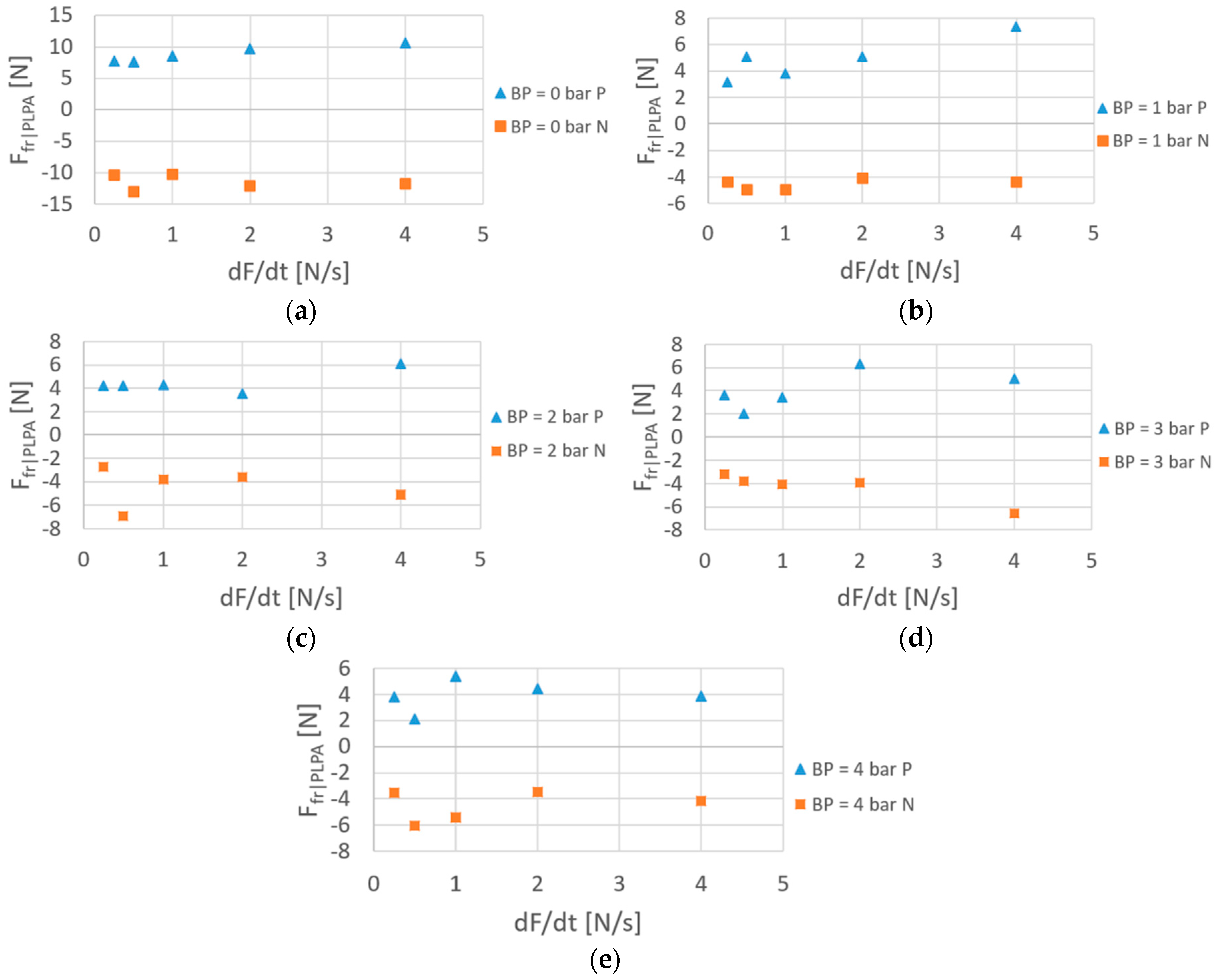
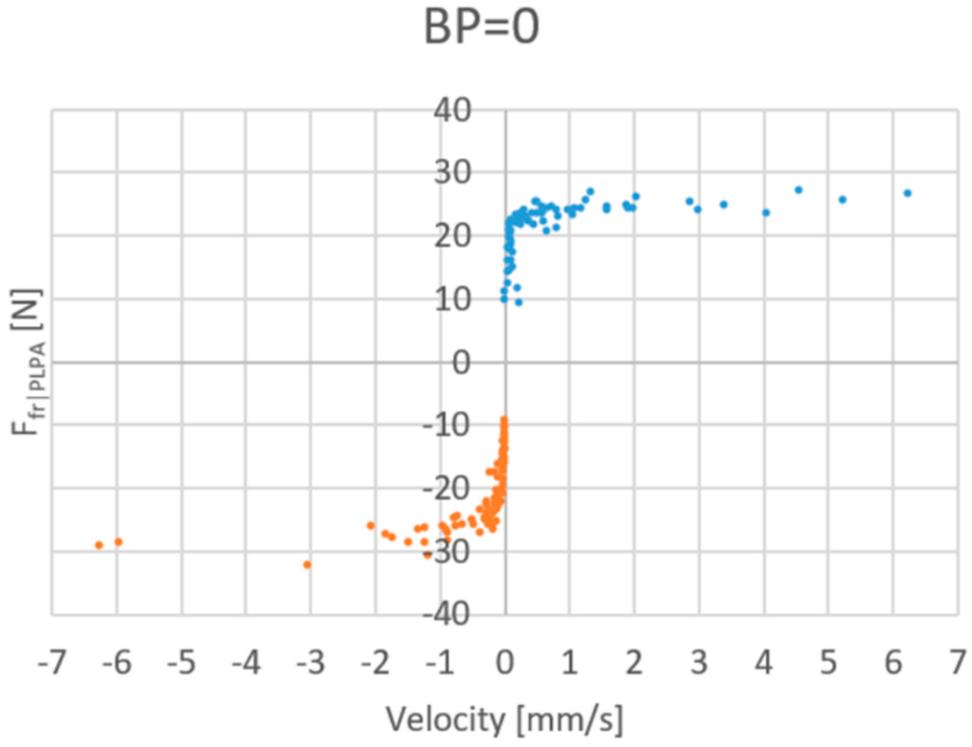
3.2.1. Static Friction
In the static friction experiments, the pressure in one chamber was kept constant while in the other chamber, it was increased until motion was detected. This was performed using the pressure-reducing valves as shown in Figure 11. Figure 12 shows the results obtained for negative (N) or positive direction motions (P), different backpressure values (0, 1, 2, 3, 4 bar), and force time gradients (0.25, 0.5, 1, 2, 4 N/s) obtained by changing the pressure inside the chambers with time.
Figure 11.
Experimental setup for the static friction force assessment of the PLPA.
Figure 12.
Static : influence of the force gradient and backpressure.
Regarding Figure 12, when there is no backpressure, static friction presents around double the value it has in the cases when there is backpressure. For instance, for the 2 N/s rate, the static friction force is 10 N for 0 bar backpressure, while it is 5 N for 1 bar backpressure. This is an interesting result that had already been found in [12] for positive direction motions. A possible justification for this is the fact that when there is no backpressure, only the active chamber is performing work to push the rollers apart; when there is backpressure, both chambers are pushing the rollers apart and, by doing so, the contact area inside the hose tends to be reduced. Consequently, so does the PLPA’s static friction. In addition, as also concluded in [12], there was not any significant difference on the results caused by the force gradient.
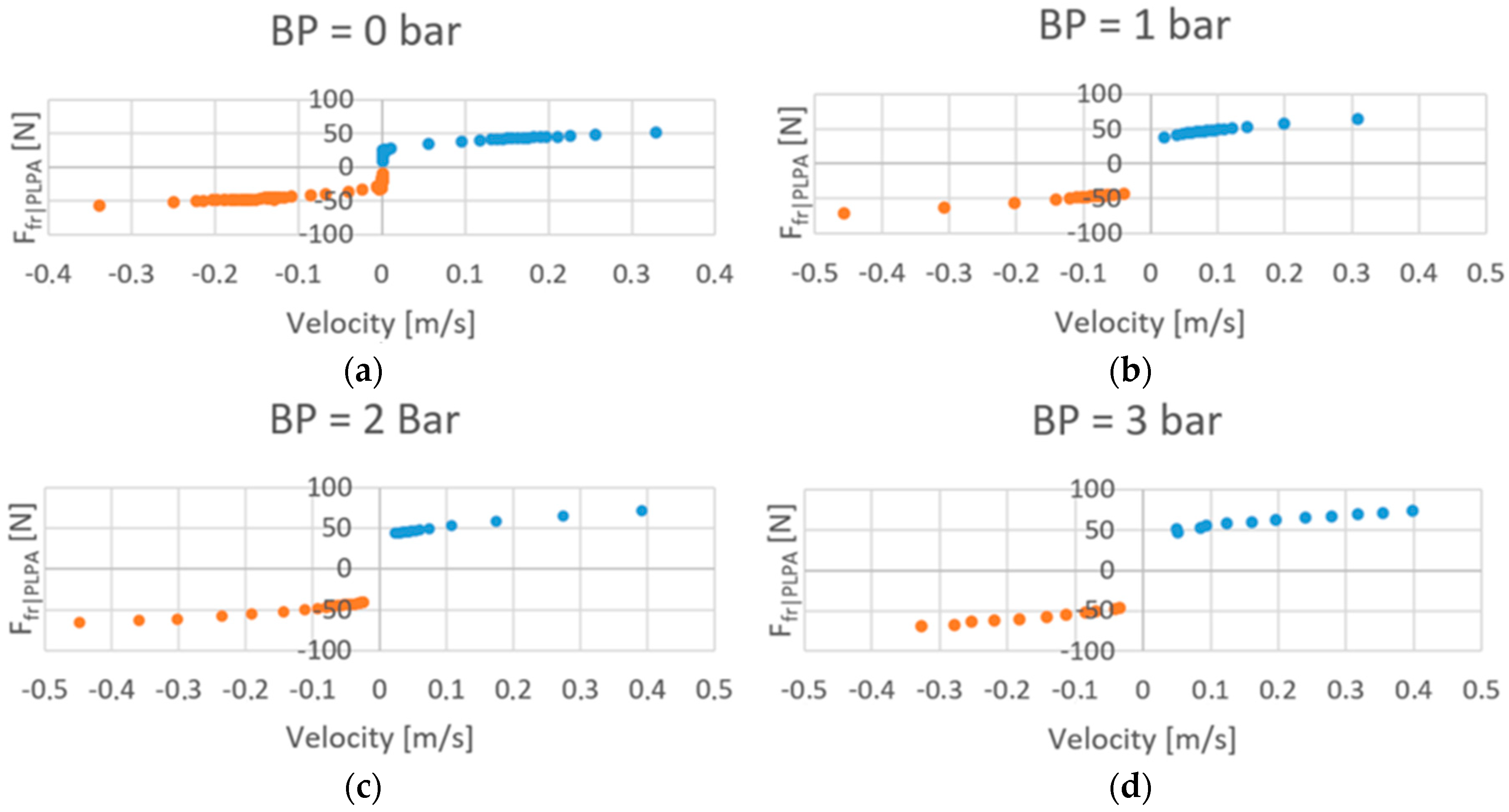
3.2.2. Viscous Friction
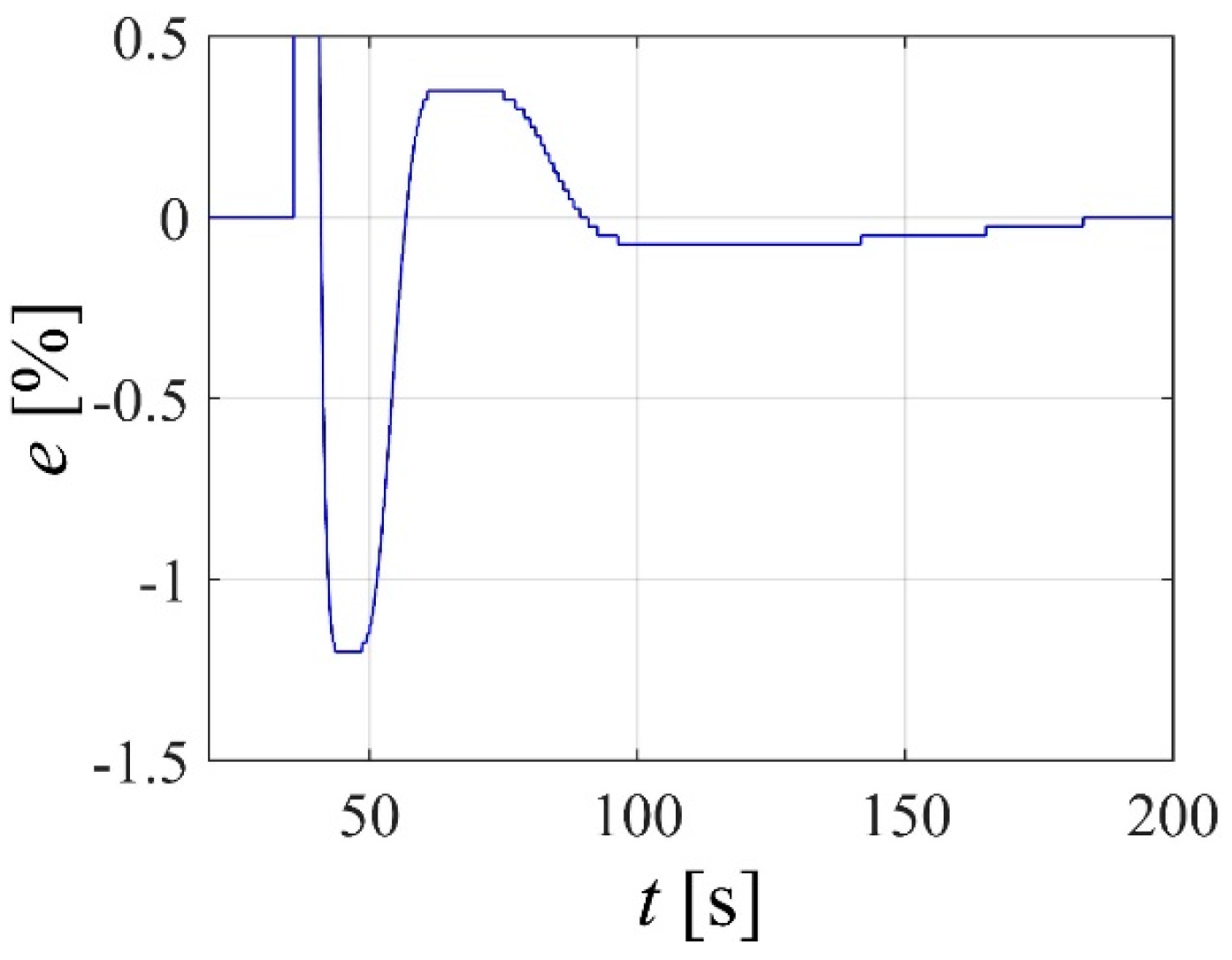
The experiments to determine the viscous friction of the PLPA were performed by imposing a constant velocity to the actuator using the servo valve connected to one chamber and connecting the other chamber to the atmosphere. The backpressure was increased from 0 to 3 bar with a 1-bar step [12]. Given the limited stroke of the actuator, constant velocities only up to ca. 0.5 m/s could be attained.
The viscous friction results are presented in Figure 13, where it can be seen that the viscous friction component of is essentially symmetrical. Interestingly, and contrary to what happens in [12], little dependency on backpressure can be verified: friction values are slightly lower when there is no backpressure, but essentially no difference can be found in the 1 to 3 bar backpressure range. This important result might be justified by the fact that while in [12] the position between rollers was imposed, in this study, the force between rollers is imposed.
Figure 13.
Viscous force at different backpressure levels.
To determine the friction characteristic behavior near zero velocity, the viscous force experiments were made at very low velocities with no backpressure. Figure 14 presents the results obtained for velocities from –7 to +7 mm/s. A very steep friction drop under ±1 mm/s is noticed, but no Stribeck effect nor could any discontinuity be found.
Figure 14.
Viscous force with BP = 0 bar, around zero velocity.
4. PID Type Control
In order to provide preliminary results of the potential results obtainable with this type of actuators, a PID-type controller was developed and tuned according to Ziegler–Nichols tuning rules. Then, these parameters where experimentally fine-tuned. Figure 15 presents the error response obtained, in percentage of the 20 mm amplitude step applied.
Figure 15.
Closed-loop step results.
Although the controller is incapable of providing a fast dynamics (taking about 4 s to reach a 2% error band), there is a low overshoot (around 1.2%), and zero steady-state error is achieved. These results show that contrary to what happens with a typical pneumatic actuator, zero steady-state error might be obtained with a simple PID-type controller. However, they also show that more complex controllers must be developed in order to increase the speed of response of the system, namely by incorporating acceleration or its estimates in the control law.
5. Conclusions
This paper has presented a new experimental setup of a linear peristaltic actuator as well as its experimental characterization. The setup developed can impose either force or distance between rollers. The nonlinear model of the system was developed, and a linearized model was experimentally identified. The friction and leakage characteristics of the actuator were experimentally determined. It was shown that the leakages are negligible with the common pressure levels used in industrial pneumatic systems. An interesting result is the fact that contrary to what was shown in the literature in previous studies, the friction force is essentially independent of the backpressure used. This effect is justified by the fact that in the proposed approach, the force between rollers is imposed, whilst in previous studies, the distance between rollers was forced. Generically, lower backpressures are desirable since they lead to lower energy consumption. However, since zero backpressure leads to an increase of the static friction force, the existence of a small backpressure might be desirable for control purposes in order to reduce the static friction. Future studies will study in detail this phenomenon, namely to determine if there is an optimal backpressure for control purposes. In addition, future work will focus on the development of different hoses geometries and materials that might increase the service life.
Author Contributions
Conceptualization, J.F.C. and F.G.d.A.; methodology, J.F.C. and F.G.d.A.;software, J.B.P., J.F.C.; validation, J.F.C., J.B.P. and F.G.d.A.; investigation, J.F.C., J.B.P., F.G.d.A. and M.F.; resources, J.F.C., J.B.P., F.G.d.A. and M.F.; writing—original draft preparation, J.F.C.; writing—review and editing, J.F.C., J.B.P. and F.G.d.A.; All authors have read and agreed to the published version of the manuscript.
Funding
This work was financially supported through contract LAETA—UID/SEM/50022/2013 by “Fundação para a Ciência e Tecnologia”, which the authors gratefully acknowledge.
Conflicts of Interest
The authors declare no conflict of interest.
References
- Carneiro, J.F.; Almeida, F.G. Accurate motion control of a servopneumatic system using integral sliding mode control. Int. J. Adv. Manuf. Technol. 2014, 77, 1533–1548. [Google Scholar] [CrossRef]
- Carneiro, J.F.; Almeida, F.G. Micro tracking and positioning using off-the-shelf servopneumatics. Robot. Comput. Integr. Manuf. 2014, 30, 244–255. [Google Scholar] [CrossRef]
- Carneiro, J.F.; Almeida, F.G. A macro-micro motion servopneumatic device. Proc. Inst. Mech. Eng. Part I J. Syst. Control Eng. 2012, 226, 775–786. [Google Scholar] [CrossRef]
- Merkelbach, S.; Murrenhoff, I.H.; Fey, I.M.; Eßer, B. Pneumatic or electromechanical drives—A comparison regarding their exergy efficiency. In Proceedings of the 10th International Fluid Power Conference, Dresden, Germany, 8–10 March 2016. [Google Scholar]
- Gauchel, W.; Haag, S. Servopneumatic Clamping System for the Assembly of Battery Cells in the Area of Electromobility. In Proceedings of the 10th International Fluid Power Conference, Dresden, Germany, 8–10 March 2016. [Google Scholar]
- Pinto, J.B. Desenvolvimento de Controlador de Movimento para Cilindro Pneumático de Baixo Atrito. In Departamento de Engenharia Mecânica; Faculdade de Engenharia da Universidade do Porto: Porto, Portugal, 2017. [Google Scholar]
- Rakova, E.; Hepke, J.; Weber, J. EXonomy analysis for the Inter-domain comparison of electromechanical and pneumatic drives. In Proceedings of the 10th International Fluid Power Conference, Dresden, Germany, 8–10 March 2016. [Google Scholar]
- Li, S.; Vogt, D.M.; Bartlett, N.W.; Rus, D.; Wood, R.J. Tension Pistons: Amplifying Piston Force Using Fluid-Induced Tension in Flexible Materials. Adv. Funct. Mater. 2019, 29, 1901419. [Google Scholar] [CrossRef]
- Mirvakili, S.M.; Hunter, I.W. Artificial Muscles: Mechanisms, Applications, and Challenges. Adv. Mater. 2018, 30, 1704407. [Google Scholar] [CrossRef] [PubMed]
- Pillsbury, T.E.; Wereley, N.M.; Guan, Q. Comparison of contractile and extensile pneumatic artificial muscles. Smart Mater. Struct. 2017, 26, 095034. [Google Scholar] [CrossRef]
- Falcão Carneiro, J.; Gomes de Almeida, F. Experimental characteristics of a linear peristaltic actuator. In Proceedings of the IFK 2018, 11th International Fluid Power Conference, Aachen, Germany, 19–21 March 2018. [Google Scholar]
- Falcão Carneiro, J.; Gomes de Almeida, F. Friction characteristics and servo control of a linear peristaltic actuator. Int. J. Adv. Manuf. Technol. 2018, 96, 23. [Google Scholar]
- Carneiro, J.F.; de Almeida, F.G.; Pinto, J.B. Endurance tests of a linear peristaltic actuator. Int. J. Adv. Manuf. Technol. 2019, 100, 2103–2114. [Google Scholar] [CrossRef]
- Carneiro, J.F.; Almeida, F.G. Undesired oscillations in pneumatic systems. In Nonlinear Science and Complexity; Machado, J.A.T., Luo, A.C.J., Barbosa, R.S., Silva, M.F., Figueiredo, L.B., Eds.; Springer: London, UK, 2011; pp. 229–243. [Google Scholar]
- Carneiro, J.F.; Almeida, F.G. Reduced order thermodynamic models for servopneumatic actuator chambers. Proc. Inst. Mech. Eng. Part I J. Syst. Control Eng. 2006, 220, 301–314. [Google Scholar] [CrossRef]
- Carneiro, J.F.; Almeida, F.G. Pneumatic servo valve models based on artificial neural networks. Proc. Inst. Mech. Eng. Part I J. Syst. Control Eng. 2011, 225, 393–411. [Google Scholar]
- Carneiro, J.F.; Almeida, F.G. A Neural Network Based Nonlinear Model of a Servopneumatic System. Asme J. Dyn. Syst. Meas. Control 2012, 134, 024502. [Google Scholar] [CrossRef]
- Varga, Z.; Honkola, P.-K. Mathematical model of pneumatic proportional valve. J. Appl. Sci. Thermodyn. Fluid Mech. 2012, 1, 1. [Google Scholar]
- ISO 6358 Standard, Pneumatic Fluid Power—Components Using Compressible Fluids—Determination of Flow-Rate Characteristics; International Organization for Standardization: Geneva, Switzerland, 1989; p. 14.
© 2020 by the authors. Licensee MDPI, Basel, Switzerland. This article is an open access article distributed under the terms and conditions of the Creative Commons Attribution (CC BY) license (http://creativecommons.org/licenses/by/4.0/).