Abstract
Axial hydraulic thrust is an important factor that affects safety and stability of pump turbine operation. Research and analysis of axial hydraulic thrust is of a great significance for guiding the safe and stable operation of a pumped storage power station. Since the runner shape of the pump turbine is flat and its radial dimension is large, an increase of leakage can happen easily. In order to reduce the leakage and improve the efficiency of the unit, a labyrinth ring seal is usually used in the upper crown and lower ring of the runner because the inner clearance of the seal has a great influence on the axial thrust. In order to study the influence of the change of labyrinth seal position on axial hydraulic thrust, a fluid domain model with a pressure balance pipe, upper crown clearance, and lower ring clearance is established for a pump turbine of a power station. The distribution position of labyrinth ring in the upper crown clearance is changed. The CFD numerical simulations are carried out under both 100% working load and 75% working load of turbine conditions, considering the flow in clearance areas. The research results of this paper have found that the axial hydraulic thrust of the 100% load condition is consistent with the change of the gap position compared with the 75% load condition. The amplitude of the change of the water thrust under the 100% load condition is greater. As the sealing position of the labyrinth ring in the upper crown gap moves away from the central axis, the resultant vertical and upward water thrust increases, and the operating efficiency of the unit first increases and then decreases. As the position of the labyrinth ring seal in the upper ring clearance moves away from the central axis, the resultant vertical and upward water thrust increases, and the operating efficiency of the unit first increases and then decreases. Defining the radial dimension ratio δ between the front clearance area and the total area of labyrinth ring, the closer δ is to 0.5, the unit efficiency is higher; the smaller that δ is, then the high pressure area in the upper crown clearance is smaller, and the hydraulic thrust force increases vertically. Considering a variety of factors, the clearance seal position has the optimal value. In the practical application of the project, the condition of excessive upward hydraulic thrust leading to the lifting of the unit can be avoided, and the phenomenon of excessive downward hydraulic thrust leading to the excessive load-bearing of the frame is evitable.
1. Introduction
Pumped-storage power plants play a role in peak and frequency regulation for the power grid. At the same time, their flexible adjustment capabilities can compensate for the randomness, volatility, and unpredictability of new energy sources (such as photovoltaics, wind power, etc.), and ensure the safe and economic operation of the power grid [1]. However, the characteristics of pumped-storage units consist of high water head and high-rotation speed in both directions under complex working conditions. As the mechanism of unit stability is not yet fully understood, operation accidents occur from time to time. In construction of power station, an excessive axial hydraulic thrust during operation can result in high temperature of the thrust pad, wear of the tile surface, tile burning, and load limiting operation. When the axial hydraulic thrust changes, if an upward force on the thrust bearing is received, unit lifting will happen; if a downward load on the thrust bearing is too big, a burning damage may occur. In addition, from the perspective of the transmission path of the axial force, the axial hydraulic thrust is transmitted to the load-bearing frame foundation of the plant structure through the thrust bearing. Its pulsating characteristics make it one of the main vertical dynamic loads in the vibration analysis of the hydropower plant structure. With the continuous development of large units, the study of axial hydraulic thrust becomes more and more important. While continuously improving the bearing capacity of the thrust bearing, it is very practical to research and study the characteristics of an axial hydraulic thrust thoroughly and, hence, try to reduce the axial hydraulic thrust.
In general, in order to prevent lifting accidents of pumped storage units, it is necessary to ensure that the axial force on the rotating parts is downward [2], that is, the direction of the hydraulic thrust acting on the runner is downward. When the hydraulic thrust increases, the friction power consumed by the thrust bearing also increases [3]. The component force of the water flow acting on the axial direction of the turbine runner mainly includes the axial force on the inner and outer surfaces of the runner blades, the upper crown, and the lower ring. At present, the research methods of axial hydraulic thrust mainly include three kinds of theoretical formula, experimental measurement, and numerical simulation [4]. Corresponding measures are usually taken in the design of the runner to reduce the pressure acting on the outer surface of the upper crown or lower ring of the runner in order to reduce the axial hydraulic thrust, such as setting up a sealing device, a pressure reducing plate, a pressure pressure-balance pipe, a discharge hole, and so on [5,6]. However, if the measures taken to reduce the axial hydraulic thrust are inappropriate, the direction of the axial water thrust may turn upward. If this exceeds the weight of the rotor, it may cause the unit lifting during operation, which directly affects the safe operation of the unit.
For hydraulic machinery, the flow in runner clearance has a great impact on the efficiency and flow pattern of the unit [7,8], Therefore, many scholars have carried out research and analysis in this area, which is also the theme of this paper.
Literature [9,10] reviews on the theoretical calculation method and on the CFD numerical simulation method of the leakage characteristics of the labyrinth seal were carried out, which provided a reference basis for the design and layout of the labyrinth ring. A numerical simulation of clearance flow was done; then, flow analysis of the turbine is compared with the actual operation of the real machine, and it is verified that the simulation method is accurate and effective for the model within the clearance [11]. It is found that the crown clearance has a certain effect on the hump area of the pump working condition of the water pump turbine [12]. Reference [13] conducted a full flow simulation calculation on a Francis turbine with pressure-balance pipe and sealing clearance, and analyzed the relationship between the pressure-balance pipe and the leakage of the runner seal clearance. In reference [14], the self-excited vibration of a Francis turbine caused by the clearance seal is studied, and the pressure distribution law of runner and draft tube area under the influence of the sealing clearance is obtained, which provides a reference for improving the stability of the unit; in reference [15], the influence of lower ring clearance flow on energy characteristics and flow pattern of the Francis turbine was studied; by minimizing the clearance value of the lower ring, it was found that the size of the lower ring clearance had different effects on different working conditions (mainly small flow units).
Many research studies have also been carried out for the correlation analysis of the axial hydraulic thrust from the flow simulation models in the clearance areas.
A new method for calculating the axial hydraulic thrust of a Francis turbine in simulation was proposed. It was found that the axial hydraulic thrust is greatly affected by the suction head within the clearance area of the unit [16].
The model calculation of the water pump turbine shows that the working conditions of the reversible unit are complex and changeable. The analysis found that the dominant force of the hydraulic thrust on the runner depends on the operating conditions, which makes the analysis of the hydraulic thrust even more complicated [17]. The analysis of axial force of a pump turbine under working conditions considering the flow of clearance and pressure-balance pipe was carried out, and the effect of the pressure-balance pipe on balancing the axial force is mainly discussed [18].
In engineering, it is common to set the balance plate and balance hole to balance the axial hydraulic thrust [19,20]. The pump turbine structure studied in this paper is complicated, so the pressure equalization pipeline is used to balance the axial hydraulic thrust.
Research and analysis on the axial hydraulic thrust of water pump turbines are few. Therefore, the CFD simulation for a unit considering the influence of pressure balance pipe and clearance on the axial hydraulic thrust was comprehensively carried out; the effects of different clearance models on the axial thrust and efficiency of the unit are compared in order to provide guidance in engineering.
2. Component Analysis of Axial Hydraulic Thrust
Three main components of the axial hydraulic thrust received by the runner are mainly monitored. The three parts are shown in Figure 1 (the direction of the specified force vertically upward is defined as positive):
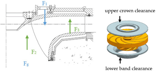
Figure 1.
Diagram of axial hydraulic trust.
F1—the axial hydraulic thrust exerted by the crown clearance on the surface of the runner, and the direction is downward (Figure 1);
F2—the axial hydraulic thrust on the runner’s inner cavity and the surface of the blades, and the direction of the turbine working condition is upward (Figure 1);
F3—the axial hydraulic thrust acting on the surface of the runner by the lower ring clearance, and the direction is upward (Figure 1);
FΣ—the resultant force of the axial hydraulic thrust on the runner, which is the resultant force of the three forces F1, F2, and F3.
Fg—the gravity of the rotating part.
The influence on the axial hydraulic thrust of many factors, which include the equalizing pressure ability of pressure-balance pipe and the upper crown and lower ring clearance flow, were comprehensively considered within the calculation domain. Since the axial hydraulic thrust acting on the runner is mainly the water pressure generated by the upper crown clearance and the lower ring clearance on the runner, plus the difference of the pressure on the runner itself, the effect of clearance flow in the analysis of axial force is important.
3. Numerical Calculation
3.1. Mathematical Model
The CFD numerical model was used to simulate the internal flow of the prototype pump-turbine and to analyze the results. In the simulation, the influence of density fluctuations was neglected, but the change of average density was included, and the turbulence governing equation was averaged over time. The tensor representation of the continuous equation and the momentum equation is as follows:
Among them, except for the average of the pulsation value over time, the upper scores of the other averages over time have been removed. is the density and P is the pressure. The index range of i and j is (1, 2, 3), in which represents the velocity components in the x, y, and z directions, is the dynamic viscosity, and is the generalized source term of the momentum conservation equation. A new unknown variable appears in the equation, which is defined as Reynolds stress:
In order to close the equation, the Reynolds stress needs to be processed. Considering the similarities between Reynolds stress and viscous stress, the eddy viscosity model provides a relatively simple method for solving Reynolds stress. According to the eddy viscosity hypothesis proposed by Boussinesq, turbulent kinetic energy is introduced:
To establish the relationship between Reynolds stress and average velocity gradient:
Among them, is the eddy viscosity (or turbulent viscosity); is the Kronecker symbol. Different related equations can be used to link the time-averaged parameters of turbulence, among which the two-equation model is the most widely used. Commonly used turbulence models mainly include the model, model, and corresponding improved models. The turbulence model used in this study is the model.
3.2. Calculation Model and Meshing
Based on the actual structure of a pump-turbine of a pumped storage power station, a watershed modeling has been carried out, in which the number of runner blades Z = 9, the number of stay vanes and guide vanes is 20, and the rotation speed is 300 rpm. The calculated fluid domain is shown in the Figure 2. The calculated fluid domain includes volute, stay vanes, movable guide vane, runner (including upper crown and lower ring clearance), draft tube, and pressure-balance pipe.
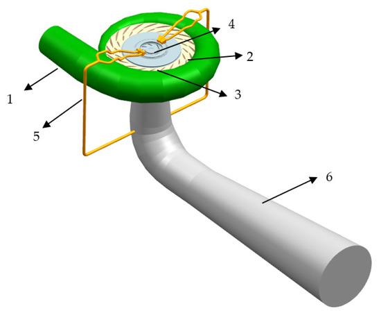
Figure 2.
Flow passage model of pump-turbine. 1. volute, 2. stay vanes, 3. guide vanes, 4. runner (including clearance), 5. pressure-balance pipe, and 6. draft tube.
In order to study the influence of the change of the seal position on the axial hydraulic thrust of the turbine under the operating conditions of the unit, the position of the labyrinth ring in the upper crown clearance seal was adjusted. The center lines of the upper crown and lower seal labyrinth rings of the original unit are basically on the same axis. In the research of this article, the position of the labyrinth ring of the upper clearance seal is shifted by 300 mm and 600 mm away from the central axis, as shown in Figure 3, which are marked as UC + 300 and UC + 600, respectively. The original sealing position model is denoted as UC + 0.
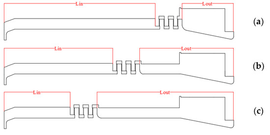
Figure 3.
Seal locations of different models. (a) UC + 0. (b) UC + 300. (c) UC + 600.
The runner shape of pump turbine is flat, and the radial dimension of the clearance area is larger than the axial dimension. Therefore, the radial length ratio of the clearance area before and after the labyrinth ring is defined, and the calculation results are discussed and analyzed. Lin is defined as the radial length of the area before the fluid in the upper crown clearance flows through the labyrinth ring, and Lout is defined as the radial length of the area after the fluid in the upper crown clearance flows out of the labyrinth ring (Figure 3). The radial length ratio δ is defined as the ratio of the radial length of the clearance area in front of the labyrinth ring to the total radial length of the clearance area, that is, δ = Lin/(Lin + Lout). The values of different models are shown in Table 1. According to the data in the table, when the δ value of the original clearance model is 0.75, the area before entering the labyrinth ring accounts for a larger proportion of the total area; when δ value of the clearance model is 0.54, which is 300 mm away from the central axis, the radial length of the front and rear areas of the labyrinth ring in the upper crown clearance is the closest; and when δ value of the model is 0.33, which is 600 mm away from the central axis, the area after leaving the labyrinth ring is relatively large. The axial hydraulic thrust of the turbine runner was calculated, compared, and analyzed with the consideration of the distribution of three kinds of clearance labyrinth rings under 100% and 75% load conditions of a pumped storage power station, and this is what provides a reference for the design of the clearance seal labyrinth ring location.

Table 1.
Comparison of parameters of different models.
The characteristics of each flow component, the ICEM, and Mesh modules in ANSYS were used to divide the mesh of each component, and a combination of structured and unstructured grids were used. In the clearance flow calculation, the processing of the clearance grid was more critical. The clearance was divided into blocks. In ICEM, a structured grid was used to divide the 5° clearance, and the grid quality was above 0.3.
The influence of the change of sealing position in the upper crown clearance was studied, so the mesh of the upper crown clearance was divided by three ways, and the mesh generated from other parts remained unchanged. Taking 75% load condition of UG + 300 model as an example, the mesh sensitivity was studied. The and were calculated under different grid quantities. As shown in Table 2, it can be seen that the variation of Case 2 and Case 3 is less than 0.5%. Computing resources, computing accuracy, and grid quality were comprehensively considered. The final choice of the upper crown clearance mesh model was Case 2.
Table 2.
Mesh sensitivity study.
In Table 2, .
3.3. Calculation Conditions and Boundary Conditions
The simulations were mainly under the operating conditions of a certain pumped storage unit with 100% and 75% load. The specific operating conditions are shown in Table 3.
Table 3.
Details of different conditions.
The fluid flows in from the volute and flows out of the draft tube. The boundary conditions are: the volute inlet is given as the total pressure inlet, and the draft tube outlet is given as the static pressure outlet. At the whole flow passage of the pump turbine, there are two dynamic and static interfaces of the runner—movable guide vane and the runner -draft tube; the two interface surfaces are set as Transient Rotor Stator. The specific values are based on the upstream and downstream of the reservoir given by the experimental results. The water level is given in combination with the pipeline loss obtained in one-dimensional calculation. Firstly, the steady calculation is performed, and the result is used as the initial condition of the unsteady calculation. The time step is 1/200 of the rotation period of the runner, and the maximum number of iterations at each time step is set to 20. The mode is set to the higher order solution term, and the convergence residual is set to 1 × 10⁻⁴.
4. Analysis of Calculation Results
Research and analysis on the change of the clearance seal position in the steady state of the turbine is carried out. Taking the 75% load condition as an example, the unit parameters obtained from the calculated prototype model are compared with the value Q11 and M11 obtained by interpolation of the model test curve. The comparison results are as follows (Table 4).
Table 4.
Comparison of calculated and test value.
In the above formulas, is unit speed; is unit discharge; is unit torque; is actual rotation speed (rpm); is nominal diameter of runner; is water head; is actual discharge (m3/s); is actual torque (Nm).
The boundary conditions of the inlet and outlet and the opening value of the movable guide vane in the calculation condition are given from the data of the real machine test, so the calculated water head is consistent with the test data. The unit speed is obtained by using Formula (6), and the unit parameters and corresponding to the test opening are obtained by interpolating the model test data of the unit according to the opening value of the calculation condition. According to the calculated flow and torque, the unit parameters and are calculated by using Equations (7) and (8). The comparison between the calculated and experimental values is shown in the table, and the error is kept within 2%, which proves that the CFD simulation adopted in this paper is reliable and effective.
4.1. External Characteristic Analysis
The formula for calculating the efficiency of the turbine condition is:
is rotation speed (rad/s).
The results of the numerical simulation of the different clearance sealing position models are analyzed, and the working efficiency of the turbine for the working conditions of different sealing positions under two loads is obtained by Formula (9) above, as shown in Figure 4. In comparison, when the position of the labyrinth ring in the crown clearance moves away from the central axis, the efficiency first increases and then decreases, and the hydraulic efficiency calculated by the original clearance distribution position model is the lowest, combined with the radial length ratio δ in Table 1. When the value changes, i.e., δ is closer to 1, and the radial size of the clearance before and after the labyrinth ring is closer, the operating efficiency of the turbine of the unit is higher. This effect becomes more significant with the increase of load and flow. As it can be seen from the vortex intensity distribution diagram of 100% load condition in Figure 5, there are vortices in front of the labyrinth ring at the entrance of the clearance at the three positions, and the size of the vortex area corresponds to the efficiency of the unit. When the seal position is offset by 300 mm, the vorticity in the area from the entrance of the crown clearance to the labyrinth ring is the smallest, and the energy dissipation generated is at the least. When the labyrinth ring position is at the design position and the offset is 600 mm, the sizes of the crown clearance and the vortex area increase, and the vortex is the cause of the change of the efficiency. Based on the analysis of the working conditions of the two load turbines, when the δ value, that is, the ratio of the radial length between the front and rear clearance areas of the labyrinth ring, the closer to 1, then the efficiency of the turbine working condition is higher. In conclusion, the distribution position of the clearance labyrinth ring will affect the flow in the clearance, thereby affecting the operating efficiency of the unit.
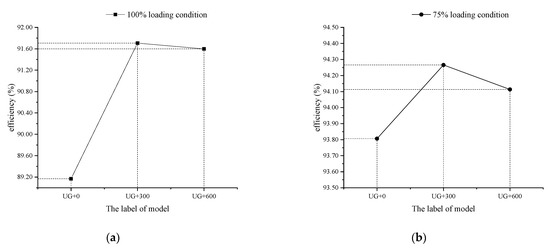
Figure 4.
Comparison of efficiency. (a) 100% loading condition. (b) 75% loading condition.
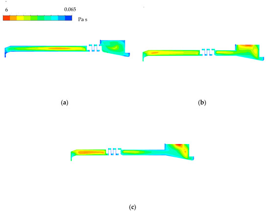
Figure 5.
Eddy viscosity distribution diagrams of upper crown clearance. (a) UC + 0. (b) UC + 300. (c) UC + 600.
Usually, the position of labyrinth ring in the clearance between the upper crown and the lower ring of pump turbine is on the same axis, and the offset is minor. This research has found that the arrangement position of labyrinth ring in the clearance between the upper crown has the optimal value for the efficiency. For the consideration of the safety and stability of the unit operation, the axial thrust has great an influence in the operation of pump turbine. Later, we will focus on the influence of the offset of the seal position in the clearance on the axial hydraulic thrust.
4.2. Analysis of Force Characteristics
It can be seen from Figure 6 that as the sealing position of the crown clearance changes away from the central axis, the resultant hydraulic thrust increases, and the trend of the change is consistent under different load conditions. From the specific analysis of the component force, the change of the resultant force of the hydraulic thrust is mainly affected by the change of the component force F1. The change of the component force F1 by the change of the position of the crown clearance seal is shown in Figure 7. When the position is far from the central axis, the vertical downward hydraulic thrust generated from the crown clearance on the runner is reduced, so the resultant force increases vertically upward.
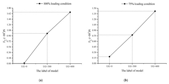
Figure 6.
Comparison of resultant force. (a) 100% loading condition. (b) 75% loading condition.
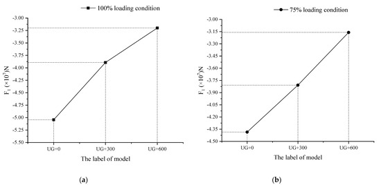
Figure 7.
Comparison of F1. (a) 100% loading condition. (b) 75% loading condition.
Taking the 100% load condition as an example, the pressure distribution inside the crown clearance is analyzed, as shown in Figure 8. It can be seen from the figure that when the fluid flows into the clearance from the runner, the pressure is higher, and the pressure decreases after passing through the labyrinth ring, i.e., the change of the position of the labyrinth ring in the crown clearance causes the internal pressure to be divided distinctively into high- and low-pressure areas. When the labyrinth ring moves away from the central axis, the value of L decreases, i.e., the high-pressure area decreases, and the crown clearance produces downward axial water on the runner, so the thrust is reduced. The major influence on the resultant axial hydraulic thrust is actually the change of F1.
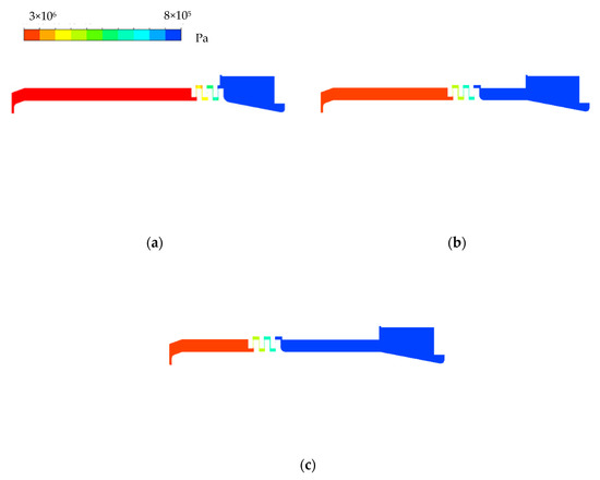
Figure 8.
Pressure distribution diagrams of upper crown clearance. (a) UC + 0. (b) UC + 300. (c) UC + 600.
The radial pressure distribution along line 1 in the upper crown clearance is shown in Figure 9. It can be seen that the distribution of the radial pressure is consistent with the pressure distribution diagram. The side of inflow in the upper crown clearance is a high-pressure area. When the fluid flows through the seal ring, the pressure decreases, and as the crown clearance seal position moves away from the central axis, the range of the high-pressure zone in the crown clearance decreases, so the downward axial hydraulic thrust generated by the crown clearance on the runner is reduced, and thus, so is the increment of the resultant force. As the sealing position in the upper crown clearance moves away from the central axis, the maximum pressure inside the high pressure zone also decreases, and this has little effect on the minimum pressure on the low pressure side.
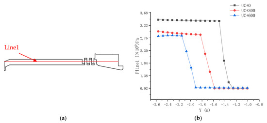
Figure 9.
Radial pressure distribution diagrams of upper crown clearance. (a) The position distribution of line 1. (b) The radial pressure distribution along line 1.
5. Conclusions
In this paper, the influence of the change of the clearance seal position of the upper crown and the lower ring of the runner on the axial hydraulic thrust is considered, and the simulation calculation of a pump-turbine prototype is carried out. The calculation results show that the change of the upper crown clearance seal position has a significant impact on the efficiency of the pump-turbine turbine and the axial hydraulic thrust on the runner.
With the change of the upper crown clearance seal position away from the central axis, the unit efficiency first increases and then decreases under both 100% load and 75% load, and the axial hydraulic thrust force on the runner increases vertically, which can reduce the load of bearing and frame. For the pump turbine studied in this paper, considering the gravity of its rotating part, the risk of unit lifting can be controlled under the condition of both 100% load and 75% load.
It is found that the change of the upper crown clearance seal position has an impact on the efficiency of the unit. The definition of the radial length ratio δ of the labyrinth ring in the upper crown clearance is introduced. When δ is close to 0.5 under 100% load and 75% load conditions, that is, when the clearance is 300 mm away from the central axis, the hydraulic efficiency of the pump turbine is at the best, increasing by about 1%. Additionally, the research and analysis of the internal flow field show, when the radial length of the front and rear clearance area of the labyrinth ring is the closest, then the internal vortex strength the lowest, and the efficiency is the highest.
The change of labyrinth ring position in the upper crown clearance will also affect the axial thrust of the unit. The pressure distribution in the upper crown clearance is analyzed. It is found that the change of the labyrinth ring position causes the changes of the high- and low-pressure areas in the upper crown clearance. When the labyrinth ring position moves away from the central axis, the high-pressure area, in which the fluid flows into the upper crown clearance but not into the labyrinth ring, decreases, while the low-pressure area where the fluid flows out of the labyrinth ring increases. The results show that the downward axial hydraulic thrust on the runner decreases, and the upward axial hydraulic thrust on the runner increases.
To sum up, in engineering, the change of the labyrinth ring position in the upper crown clearance has an impact on the efficiency and axial hydraulic thrust of the unit. When the excessive load-bearing or unit lifting happen, the sealing clearance position can be reasonably adjusted according to the actual working conditions by a CFD numerical simulation, and the negative impact of axial hydraulic thrust is reduced.
Author Contributions
Conceptualization, H.S.; methodology, H.S. and Y.L.; investigation, H.S. and J.N.; writing—original draft preparation, H.S.; writing—review and editing, Z.W; supervision, Z.W.; project administration, X.J. and Y.L. All authors have read and agreed to the published version of the manuscript.
Funding
This work was supported by National Natural Science Foundation of China (No.: 51876099).
Informed Consent Statement
Not applicable.
Data Availability Statement
Not applicable.
Acknowledgments
Thanks for the test data provided by relevant units and the support of National Natural Science Foundation of China (no.51876099).
Conflicts of Interest
The authors declare no conflict of interest.
References
- Mei, Z. Pumped Storage Power Generation Technology; Machinery Industry Press: Beijing, China, 2000. [Google Scholar]
- Jung, A.; Yan, J.; Giese, M. Development of a reliable very high-head pump turbine considering challenging hydrodynamics. In IOP Conference Series: Earth and Environmental Science; IOP Publishing: Bristol, UK, 2012. [Google Scholar]
- Dai, Y.; Wang, H.; Zhang, K.; Zheng, L.; You, G.; Kong, L.; Zhu, X.; Lou, Y. Research on axial hydraulic thrust of francis pump-turbine’s runner. J. Hydroelectr. Eng. 2005, 24, 105–113. [Google Scholar]
- Zhou, X.; Wu, H.; Su, K. Overview and discussion on hydraulic axial thrust in Francis turbine research. J. Hydraul. Eng. 2019, 50, 1242–1252. [Google Scholar]
- Li, W.; Wang, W.; Gao, H.; Gong, R.; Qian, Z. Numerical Simulation Research on the Axial hydraulic thrust of the Runner of Baihetan Hydropower Station. China Rural Water Conserv. Hydropower 2014, 12, 161–164. [Google Scholar]
- Faria, M.T.C.; Paulino, O.G.; Fernando, H.D.O.; Barbosa, B.H.; Martinez, C.B. Influence of Mechanical Draft Tube Fish Barrier on the Hydraulic Thrust of Small Francis Turbines. J. Hydraul. Eng. 2010, 136, 924–928. [Google Scholar] [CrossRef]
- Nishimura, H.; Sugiyama, K.; Tsujimoto, Y.; Koyama, H. Theoretical Estimates of Rotordynamic Fluid Forces on a Front Shroud of Francis Turbine Caused by Leakage Flow. Int. J. Fluid Mach. Syst. 2018, 11, 344–356. [Google Scholar] [CrossRef]
- Liu, Y.; Tan, L.; Wang, B. A review of tip clearance in propeller pump and turbine. Energies 2018, 11, 2202. [Google Scholar] [CrossRef]
- Zhu, G.; Liu, W. Analysis of Calculational Methods on Leakage for Labyrinth Seals. Lubr. Eng. 2006, 04, 123–126. [Google Scholar]
- Song, Z.; Zeng, Y.; Liu, X.; Yu, Z.; Qiu, S. Study on Leakage Characteristics of Eccentric Labyrinth Seal Based on CFD Tools. Mach. Tool Hydraul. 2018, 46, 150–153, 179. [Google Scholar]
- Han, X.; Liu, W.; Wei, X. Numerical Analyze of Clearance Flow of Tubular Turbine. Large Electr. Mach. Hydraul. Turbine 2009, 4, 52–54. [Google Scholar]
- Huang, S. Numerical Research on Influence of Upper Crown Clearance on Flow Characteristics of Pump-turbine Pump Working Condition; Xi’an University of Technology: Xi’an, China, 2019. [Google Scholar]
- Liang, W.; Dong, Y.; Zhao, D.; Wei, M. The influences of relief pipes of Francis hydraulic turbine on the flow field of the sealing clearance and its environs. J. Hydroelectr. Eng. 2008, 2, 135–140. [Google Scholar]
- Ma, W.; Liang, W.; Nan, H.; Zhao, D.; Li, J.; Dong, Y. The influence of sealing clearance value of Francis runner on the unit stability. J. Hydroelectr. Eng. 2010, 29, 219–223. [Google Scholar]
- Wu, Z.; Liang, W.; Dong, W.; Gao, G.; Chen, D. Influence of seal clearance of runner on internal fluid field in Francis turbine. Trans. Chin. Soc. Agric. Eng. 2020, 36, 23–29, 337. [Google Scholar]
- Ji, X.; Li, X.; Su, W.; Lai, X.; Zhao, T. On the hydraulic axial thrust of Francis hydro-turbine. J. Mech. Sci. Technol. 2016, 30, 2029–2035. [Google Scholar] [CrossRef]
- Li, W.; Shi, W.; Jiang, X.; Zhou, L.; Jiang, Z. Numerical calculation and experimental study of axial force on multistage centrifugal pump. Trans. Chin. Soc. Agric. Eng. 2012, 28, 52–59. [Google Scholar]
- Lin, W.; Mao, Z.; Li, X.; Xu, B.; Tao, R.; Wang, Z. Analysis and Improvement of the Axial Force on Pump Turbine in Pump Mode. Trans. Chin. Soc. Agric. Mach. 2020, 51, 132–137. [Google Scholar]
- Li, J.; Zhang, Y.; Liu, K.; Xian, H.; Yu, X. Numerical simulation of hydraulic force on the impeller of reversible pump turbines in generating mode. J. Hydrodyn. 2017, 29, 603–609. [Google Scholar] [CrossRef]
- Zhang, L.; Jin, J.; Xiao, Z.; Li, Y. Numerical Investigation of the Effect of Balancing-Hole on the Axial Force of a Partial Emission Pump. In ASME Joint US-European Fluids Engineering Division Summer Meeting Collocated with the ASME International Conference on Nanochannels; American Society of Mechanical Engineers: New York, NY, USA, 2014. [Google Scholar]


Publisher’s Note: MDPI stays neutral with regard to jurisdictional claims in published maps and institutional affiliations. |
© 2021 by the authors. Licensee MDPI, Basel, Switzerland. This article is an open access article distributed under the terms and conditions of the Creative Commons Attribution (CC BY) license (https://creativecommons.org/licenses/by/4.0/).