Abstract
This numerical study compares the wave field generated by the spectral wave action balance code, SNL-SWAN, to the linear-wave boundary-element method (BEM) code, WAMIT. The objective of this study is to assess the performance of SNL-SWAN for modeling wave field effects produced by individual wave energy converters (WECs) and wave farms comprising multiple WECs by comparing results from SNL-SWAN with those produced by the BEM code WAMIT. BEM codes better model the physics of wave-body interactions and thus simulate a more accurate near-field wave field than spectral codes. In SNL-SWAN, the wave field’s energy extraction is modeled parametrically based on the WEC’s power curve. The comparison between SNL-SWAN and WAMIT is made over a range of incident wave conditions, including short-, medium-, and long-wavelength waves with various amounts of directional spreading, and for three WEC archetypes: a point absorber (PA), a pitching flap (PF) terminator, and a hinged raft (HR) attenuator. Individual WECs and wave farms of five WECs in various configuration were studied with qualitative comparisons made of wave height and spectra at specific locations, and quantitative comparisons of the wave fields over circular arcs around the WECs as a function of radial distance. Results from this numerical study demonstrate that in the near-field, the difference between SNL-SWAN and WAMIT is relatively large (between 20% and 50%), but in the far-field from the array the differences are minimal (between 1% and 5%). The resultant wave field generated by the two different numerical approaches is highly dependent on parameters such as: directional wave spreading, wave reflection or scattering, and the WEC’s power curve.
1. Introduction
As wave energy converter (WEC) technology matures from deployments of individual WECs for testing and demonstration, to wave farms consisting of multiple WECs for utility-scale power generation, it will be increasingly necessary to understand and quantify the effect of these WECs on the surrounding wave field. Deployment of WECs in wave farms has the potential to affect both the near-field and far-field and may have an impact on the nearshore environment and processes. In order for wave energy projects to be permitted, and thus for wave energy to be a viable part of our renewable energy portfolio, we must have numerical tools capable of modeling the effects of wave farms on their surrounding environment. Numerical tools are especially important due to the lack of data available from open ocean deployments of wave farms; until data are available, we must rely on simulations.
In the literature, there are many different numerical approaches for modeling WEC devices and wave farms. Each numerical approach has its benefits and limitations, and thus, the best method is highly dependent on the intended application. Folley (2016) provides a comprehensive review of techniques for modeling individual WECs and wave farms []. In his book, Folley splits the numerical approaches into the following categories: frequency-domain models, time-domain models, and spectral-domain models. Frequency-domain models include linear potential flow methods such as the boundary element method (BEM) codes WAMIT [] and NEMOH []. Time-domain models include numerical methods based on the Cummins’ impulse response formulation, which allows for the inclusion of nonlinearities; these methods are often referred to as wave-to-wire models []. Spectral-domain models include numerical methods based on the spectral action balance equation, such as the codes SWAN and TOMAWAC [,]. The rate of change of the action density is governed by the action density balance equation. This equation includes wave kinematics, variations in depth and currents, sources, and sinks but is not phase resolving.
To estimate wave field effects due to the presence of a wave farm in an open ocean environment, the most common approach is to apply spectral-domain models. In spectral-domain models, the spectral action balance equation includes an energy sink term to model the WEC’s energy extraction as an obstacle in the computational domain. Many researchers have used this approach to estimate a wave farm’s potential impact on the wave field and on the nearshore environment. Millar et al. (2007) modeled a planned wave farm at the WaveHub site off the north Coast of Cornwall in the UK using a SWAN obstacle with varying amounts of transmission []. Smith et al. 2012 furthered the WaveHub study by modifying the SWAN code to include a frequency- and direction-dependent WEC obstacle based on the WEC’s power performance []. Silverthorne and Folley (2011) added a similar frequency- and direction-dependent obstacle in the spectral code TOMAWAC and modeled a 40 WEC wave farm using this approach []. Researchers at Oregon State University performed a series of 1, 3, and 5 WEC array wave tank experiments and then modeled the resulting wave field in a modification of the spectral-domain code SWAN, and in the BEM code WAMIT [,,]. Rusu and Onea (2016) used a computational framework coupling SWAN with a circulation model (navy standard surf model) to study the influence of a wave farm’s distance from shore off the Portuguese coast on the nearshore wave propagation and coastal circulation []. Greenwood et al. (2016) compared the performance of spectral and Boussinesq methods in MIKE for modeling small arrays of oscillating surge WECs []. Venugopal et al. (2017) modeled arrays of attenuators and oscillating surge WECs in MIKE 21 Spectral Wave using reflection, absorption coefficients derived from the boundary element method (BEM) code WAMIT [].
Researchers at Sandia National Laboratories have developed SNL-SWAN, a modified version of the open source SWAN code to include a WEC Module to extract energy from the model domain based on the WEC’s power performance []. Sensitivity analyses have been performed using the SNL-SWAN code to model the nearshore effects of wave farms by varying the the WEC type, spacing, and number of WECs []. SNL-SWAN has also been used to drive circulation models to understand the effects changes in the nearshore wave environment may have on circulation patterns []. While results from the SNL-SWAN code have been compared to experimental data, the resolution of experimental data from point measurements does not allow for the complete assessment of SNL-SWAN’s performance throughout the near- and far-field [].
This paper extends previous work modeling wave field effects produced by individual WECs and multiple WEC wave farms with spectral-domain models by comparing the performance of SNL-SWAN with the linear-wave, BEM code WAMIT. The objective of this work is to identify the conditions where SNL-SWAN and WAMIT agree and differ in order to better understand the limitations of this numerical approach to model the wave field. The work presented in this paper is an extension of the single WEC pitching flap results presented in McNatt et al. (2017), by expanding the analysis to include two addition WEC types (point absorber and hinged raft), and multiple device WEC arrays []. The effort is based on the fact that phase-resolving BEM codes better model the physics of wave-body interactions and thus simulate a more accurate wave field than spectral wave models. Comparing SNL-SWAN to WAMIT, as opposed to using experiments, has the advantages that BEM codes are faster and less expensive to run, results are precise and repeatable, arbitrarily large areas and resolutions can be assessed, and comparison can be made throughout the computational domain (not just at measurement locations). The comparison between SNL-SWAN and WAMIT is made over a range of incident wave conditions (short-, medium-, and long-wavelength waves), with various amounts of directional spreading, and for three WEC archetypes: a point absorber (PA), a pitching flap (PF) terminator, and a hinged raft (HR) attenuator.
2. Numerical Methods
2.1. Spectral-Domain
The spectral-domain code used for the numerical analysis presented in this paper is SNL-SWAN, a modification of the open-source SWAN (Simulating WAves Nearshore) code, developed by TU Delft [,]. In spectral codes like SWAN, waves are propagated to each grid point in the domain via the action density balance equation, and the waves are represented by wave spectra. The SNL-SWAN code includes the addition of a WEC Module which improves how SWAN accounts for power performance of WECs and the effects on the wave field. SNL-SWAN works differently than baseline SWAN in that it determines the frequency-dependent transmission coefficient, , for the WEC obstacle based on the device’s power performance data, and the incident wave climate within the model. Directional-dependence is possible but was not investigated at this stage, since finding quality information on WEC performance relative to wave direction was challenging. WEC power performance data can be input as a relative capture width (RCW) curve, which can be obtained through experimental data or other numerical models. The transmission coefficient, , determined by SNL-SWAN is used to extract energy as a function of the incident wave frequency, , from the WEC obstacle location in the spectral wave action balance equation []. The formula used to convert the relative capture width (RCW) curve to a coefficient is defined in Equation (1).
where is the power absorbed by the WEC, and is the incident wave power. More information on the RCW curve is provided in Section 3.1.
2.2. Frequency-Domain
The frequency-domain code BEM code used for the numerical analysis presented is the commercial code WAMIT []. WAMIT is a BEM code developed by MIT that solves the linear-wave boundary-value problem. BEM codes are based on linear wave theory, which is based on the assumptions that the fluid is inviscid and the flow is irrotational, and wave heights and body motions are small relative to the incident wave length. This allows for the fluid to be represented by a velocity potential, , and for the wave amplitude, body forces, and body motions to be solved in the frequency domain. WAMIT solves for velocity potential using Green’s functions, ensuring that body-surface boundary conditions and the free-surface and bottom boundary conditions are met. Under the assumptions of linearity, the boundary-value problem can be separated into the incident, diffracted, and radiated waves. This allows the free surface wave elevation to be reconstructed through linear superposition of the incident, diffracted, and radiated waves at each frequency. In WAMIT, the WEC’s power absorption is calculated by assuming a linear damping proportional to the velocity in the power take-off (PTO) degree of freedom (DOF).
2.3. Comparison
The codes used in this study represent fundamentally different numerical approaches. SNL-SWAN implements WEC wave field effects parametrically based on their energy absorption characteristics and models the WEC as an energy sink, while WAMIT computes the wave field of the WEC under the assumptions of linear wave theory. A comparison between the two codes and an overview of their application to modeling the WEC impact on the wave field is summarized in Table 1.

Table 1.
Comparison of SNL-SWAN and WAMIT for computation of the wave energy converter (WEC) wave field.
This comparison is intended to highlight the fact that these numerical approaches serve different purposes. SNL-SWAN is primarily used to propagate wave spectra over realistic bathymetry in order to assess nearshore effects; it is not intended to model near-WEC wave field. By contrast, WAMIT is primarily used to compute WEC body forces, motions, power absorption, and the near-WEC wave field, and it is not intended to model the WEC wave field over a large area with varied bathymetry. Because WAMIT models wave–structure interaction, whereas SNL-SWAN implements it parametrically, we expect the output of SNL-SWAN and WAMIT to differ the most in the near-WEC wave field. In the far-field, where wave–structure interaction due to radiation is diminished, and directional spreading dissipates wave energy, we expect SNL-SWAN and WAMIT to have the most similarity. The purpose of this study is to identify the range of applicability of the SNL-SWAN code for model wave field effects, as compared to that of WAMIT.
3. WEC Types
For the numerical study between SNL-SWAN and WAMIT, three WEC archetypes were selected: a pitching flap (PF) terminator, a point absorber (PA), and a hinged raft (HR) attenuator, shown in Figure 1. These WECs were selected to represent the breadth of existing WEC technologies due to their varying size, power performance, and modes of motion. A pitching flap was selected to represent terminator type WECs similar to the WaveRoller. The PF is a bottom-mounted WEC with a flap that rotates in pitch relative to seabed, and it is used to generate power. A half-submerged sphere was chosen to represent point absorber-type WECs similar to the Power Buoy. The PA absorbs power in heave motion relative to the seabed. A hinged raft similar was selected to represent attenuator-type WECs similar to the Pelamis. The HR consists of two hulls with a single hinge used for generating power through the relative pitch motion. An overview of the WEC’s dimensions and modes of motion is summarized in Table 2. For each WEC, Table 2 lists the active degrees of freedom (DOF), the power take-off (PTO) DOF, the dimensions of the device, the water depth in which the device is located, and an image of the WEC.
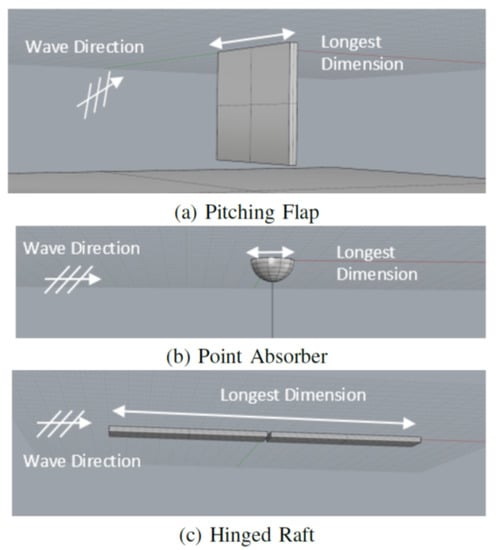
Figure 1.
Image of the of the selected WEC types: pitching flap (PF), point absorber (PA), hinged raft (HR).

Table 2.
Overview of the selected WEC types: PF, PA, HR.
3.1. Power Performance
Each WEC’s power performance was evaluated with wave spectra for s; see Section 4 for additional details. The damping value for each WEC was tuned to maximize its power absorption for the JONSWAP and Bretschneider spectra at s and m. For the array tests, the s spectrum was removed, and the s spectrum was added as a more realistic sea state. The hinged raft and the point absorber absorb more power in the s spectra than the others. Figure 2 shows the power performance of each WEC as a function of frequency overlaid with the nondimensionalized spectral sea states. This dimensionless characterization of a WEC’s power performance, a function of wave frequency, is referred to as the relative capture width (RCW) curve. The RCW is defined as a ratio of the power absorbed by the WEC, to the incident power available to the WEC; see definition in Equation (2).
where is the radial wave frequency, w is the device width, is the PTO damping, is the WEC’s motion response, is the water density, g is gravitational constant, and is the wave group velocity (a function of and water depth, h). The diamond markers in Figure 2 are the RCW values that were provided to SNL-SWAN at 101 discrete wave frequencies. While a WEC’s RCW can be greater than 1 due to the WEC’s antennae effect, where a device absorbs more power than what is available over its diameter, SNL-SWAN requires the RCW to be capped at 1 (corresponding to 100% energy absorption) because the code cannot extract more energy than is available incident to the WEC obstacle width.
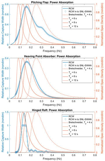
Figure 2.
Normalized wave spectra with WEC relative capture width curves: (top) pitching flap; (middle) point absorber; (bottom) hinged raft.
3.2. Characteristic Dimensions
The dimensions of each WEC archetype are listed in Table 2. In the context of this numerical analysis, the characteristic width, w, refers to the width of the WEC perpendicular to the incident wave direction. This corresponds to the dimension used to calculate the relative capture width (RCW), and the WEC obstacle length in SNL-SWAN, see Table 2 and Equation (2). The characteristic diameter, d, is defined as the diameter of the hemisphere with the equivalent submerged volume, where V is the submerged volume of the WEC, as shown in Equation (3).
The characteristic diameter is used in the Results section to nondimensionalize length values and to define the size of the area over which quantitative measures of the wave field are taken. The basis for its definition is that the impact of the WEC on the wave field should be roughly proportional to the volume of the fluid that it displaces.
4. Wave Conditions
The selected wave cases have periods of s, which represent short- (25 and 56 m), medium- (100 m), and long-wavelength (212 m) waves, respectively. The medium and long wave periods were chosen because they are representative of sea states at potential WEC deployment sites in the U.S. []. The short wave cases were chosen due to their high potential for wave scattering. The ratio of the device size to the wave length is often called the diffraction coefficient []. The smaller the value of the diffraction coefficient, i.e., the shorter the wave, the larger the impact of the device on the wave field due to scattering.
An overview of the wave cases run in this numerical study is provided in Table 3 for the single WEC and WEC array cases. The selected wave conditions differ between single WEC cases and WEC array cases. The revised wave conditions are based on findings from the single WEC numerical analysis which led to modification of the sea states, and reduction in the number of cases for the WEC array analysis. For example, the 4 s was used to evaluate the single WEC results; however, when running the WEC array cases, 6 s wave was run because it was more representative of real seas. Similarly, JONSWAP spectra were only run for the single WEC cases, because the results from the JONSWAP and Bretschneider results showed minimal differences.

Table 3.
Summary of wave conditions run for individual WEC and WEC array cases.
Irregular Waves
An overview of the irregular sea states run in this numerical study is provided in Table 3 for the single WEC and WEC array cases. For each of the specified wave periods, s, two sets of wave spectra were defined, a JONSWAP (JS) and a Bretschinder (BS). The wave spectra used for the irregular sea states run in this numerical study are provided in Figure 3 and shown in nondimensional form with the RCW in Figure 2. While an extensive analysis of a wide set of irregular wave conditions was run, only a subset of the irregular wave simulations will be included in this paper. These results provide an overview of the findings from the extensive numerical analysis by highlighting a subset the cases that are representative of the overall numerical analysis.
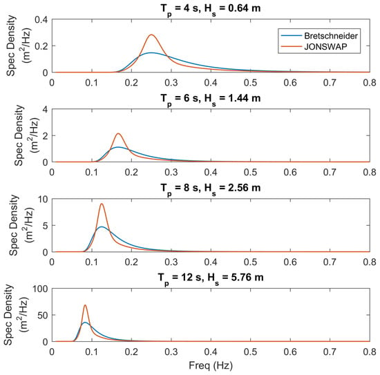
Figure 3.
Bretschneider and JONSWAP wave spectra used for irregular wave cases.
5. Comparison Metrics
5.1. Wave Field Disturbance
At each location in the wave field, , the disturbance caused by the body on the wave field can be described by the wave field disturbance coefficient defined in Equation (4).
where is the significant wave height at any field point in the domain, is the incident significant wave height. The origin is defined as the location of the WEC for single WEC cases, and as the middle of the array for the array cases. is nondimensional; it represents the amount that the wave field is altered by the presence of the body. For example, a value of means that the wave height at that location is 20% higher than it would be with no body present, and a value of means that the wave height is 20% lower. In SNL-SWAN literature, a similar quantitative measure is used called the transmission coefficient, which is the ratio of the wave height in the lee of the device to the incident wave height, . Refer to Figure 4 for an example of (blue line), and (red dashed) line as transects. Where is the WAMIT wave field coefficient, is the SNL-SWAN wave field coefficient.
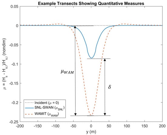
Figure 4.
Example transects showing the quantitative metrics.
5.2. Wave Field Difference
The difference at a given point, , between the SNL-SWAN and WAMIT wave fields is defined in Equation (5).
where is the WAMIT wave field coefficient and is the SNL-SWAN wave field coefficient. The difference will be positive if WAMIT predicts a higher wave field disturbance than SNL-SWAN and negative if it predicts a lower. Since is normalized by , is a percentage difference; e.g., a value of means that the WAMIT wave field is 20% higher than that of SNL-SWAN. Refer to Figure 4 for an example of .
5.3. Normalized, Mean-square, and Root-Mean-Square Difference
Over a given region of points, the difference can be quantified using the well-known root-mean-square (RMS) difference or , as defined in Equation (6).
The root-mean-square calculation can also be applied to the WAMIT wave field alone to get a measure of the disturbance of the device on the wave field, which we shall call the RMS wave field disturbance, defined in Equation (7).
The ratio of the to creates another useful measure, the normalized RMS difference, defined in Equation (8).
This value normalizes the RMS difference and can be viewed as a percentage difference (i.e., means there is a 20% difference). The lower the value of , the better the result. The meaning of the value is given in Table 4.

Table 4.
Meaning of the values of the normalized root-mean-square difference, .
5.4. RMS Difference Region
In this study, we want to know how well SNL-SWAN compares with WAMIT over various regions. We do not expect the wave field to match particularly well near the WEC(s), but SNL-SWAN should model the wave field accurately in the far-field. Therefore, the SNL-SWAN and WAMIT wave fields are compared over a range of circles centered on the WEC or WEC array at various radial distances. In this way, we can compare the wave fields both in the near-field (region near the WEC(s)) and in the far-field to observe trends in the fit as a function of distance.
5.5. Results Description
Detailed plots of the simulation results are shown in Section 6 for the single WEC cases and Section 7 for the WEC array cases. Each section provides results presented as a series of figures; a description of the information provided in each of these figures is provided below.
5.5.1. Wave Field Plots
- (a)
- SNL-SWAN wave field: This is the wave field produced by SNL-SWAN. Incident waves travel in the positive x direction, as indicated by the arrow. The plot is of the wave field disturbance coefficient, , which is equal to significant wave height at a field point normalized by incident significant wave height. The wave field coefficient represents the change in wave height due to the presence of the WEC: A value of 0 means the wave field is undisturbed, which is represented by green in the plot; a positive value means wave heights are higher than they would otherwise be (hot colors); and a negative value means there is a wave shadow (cool colors). It should be noted that because SNL-SWAN only removes energy from the wave field, the wave field coefficient values are always negative. The WEC or array are centered at . Profiles of the WECs are drawn on the plots.
- (b)
- WAMIT wave field: this is the wave field produced by WAMIT. Similar to the SNL-SWAN wave field, it is a plot of the wave disturbance field coefficient, and the WEC or array is centered at (0,0). However, since WAMIT models wave scattering (reflection) and radiation (wave produced by the motion of the device) as well as wave energy absorption, the plots show increases as well as decreases in the wave height.
- (c)
- Difference wave field: This is a plot of the difference between the WAMIT wave field and the SNL-SWAN wave field in terms of their wave field coefficient, . A value of 0 means there is no difference between the two wave fields (represented by the pink color). A positive value means that the WAMIT wave height is greater than the SNL-SWAN wave height at that point (represented by a light color). A negative value means that the WAMIT wave height is lower than the SNL-SWAN wave height at that point (represented by a dark color). In this plot, there are two blue circles centered around the WEC(s), referred to as the difference region. It is over these circles that quantitative values are given. The radii of these circles are:
- Single WEC: r = 5, 10 d;
- WEC Array: r = 30, 100 d;
where d is the characteristic diameter of the WEC (see Table 1). The radii of 5 and 10 d were used during the initial single WEC analysis, and larger regions are considered for the WEC array analysis.
5.5.2. RMS Difference/Disturbance Plots
The values shown in these plots are the normalized RMS difference () over circles at the two radii, and the RMS wave field disturbance () over those same circles. This plot shows the normalized RMS difference on the left axis corresponding to the solid blue line and the RMS disturbance on the right, which corresponds to the dashed red line. The x-axis is radial distance from the center of the circle nondimensionalized by the characteristic diameter. The RMS values are taken over circles of increasing radius.
5.5.3. Spectra Plots
The spectra plots show omnidirectional spectra at fout locations in the wave field. These locations vary between the single WEC cases and the array cases, corresponding to the following (x,y) coordinates in m:
- Single WEC: (−100,0), (50,0), (500,0), (500,100);
- WEC Array: (−20d,0), (20d,0), (100d,0), (86.6d,50d).
This plots show the incident spectrum as a dashed line, the SNL-SWAN spectrum as a blue lined, and the WAMIT spectra as a red line. The locations of the output spectra are indicated by the numbered points in the wave field plots.
6. Single WEC Cases
This section describes key characteristics of the results for the single WEC comparison. The results presented in this paper include the single WEC simulation cases listed in Table 5. These single WEC cases were selected to highlight examples where there is both good agreement between SNL-SWAN and WAMIT and where there is poor agreement. Analysis of the simulation results for of each of these single WEC cases is provided in the following sections.

Table 5.
Individual WEC results with the normalized root-mean-square (RMS) difference, , and RMS wave field disturbance, . The spread (or wave spreading, parameter is of the form, , where higher s values indicate a narrower directional spectrum.
6.1. Short Waves
As discussed in the theory section, SNL-SWAN only models energy extraction and therefore does not model wave reflection, radiation, and scattering by the WEC, which are captured by WAMIT. As a result, the short wave period, s, case listed in Table 5 and shown in Figure 5, Figure 6 and Figure 7 has very large discrepancies in both the quantitative and qualitative metrics. These differences are especially apparent in Figure 5, where WAMIT produces a scattered wave in front of the WEC, an effect that SNL-SWAN cannot produce with pure energy extraction. The difference between WAMIT and SNL-SWAN in the lee is also nontrivial, as demonstrated by and 5 d downwave and at 10d. However, Figure 7 demonstrates that while the wave field may not have fully captured the WEC-wave effects, the difference in spectral energy content between the two codes is minimal by 500 m downwave.
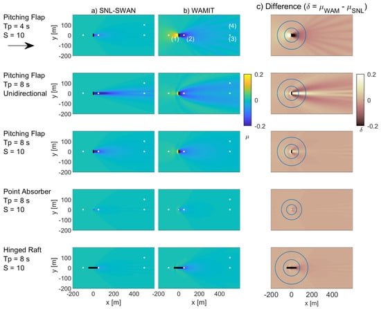
Figure 5.
Single WEC Wave Field: (a) SNL-SWAN wave field, (b) WAMIT wave field, (c) difference wave field .
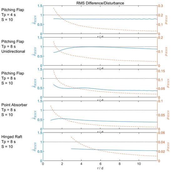
Figure 6.
Single WEC RMS difference/disturbance: Normalized RMS difference, RMS disturbance, and plot of values over concentric circles as a function of radial distance.
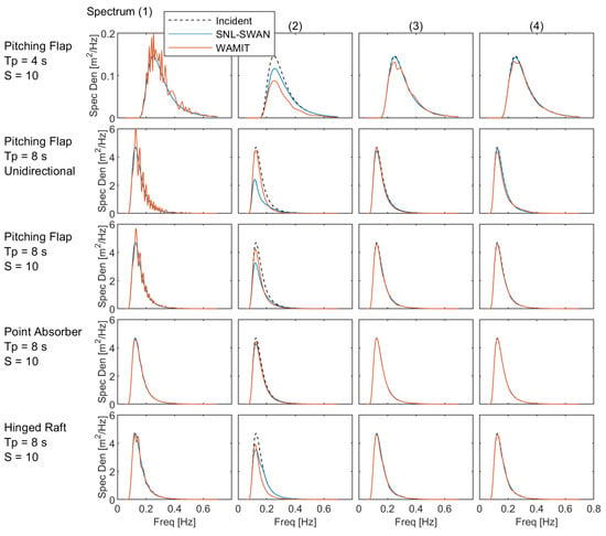
Figure 7.
Single WEC Spectra: Plots of the omnidirectional wave spectra at the four points marked in the WAMIT wave field.
6.2. Unidirectional Waves
Similar to the numerical analysis of the short wave case, unidirectional waves are not well modeled in SNL-SWAN. As discussed in the theory section, SNL-SWAN models energy extraction from the WEC and propagates the spectral wave energy from one grid point to the next. Without directional spreading, the wave field in SNL-SWAN in unable to recover in the lee of the WEC obstacle. As a result, cases with planar, unidirectional waves are poorly modeled in SNL-SWAN. By comparison, cases with larger amounts of directional spreading are more realistically modeled. This is demonstrated by the unidirectional wave case for the PF listed in Table 5. The numerical discrepancies from simulations in SNL-SWAN and WAMIT are shown in Figure 5, Figure 6 and Figure 7. These differences are especially apparent in Figure 5, where the wave shadow in the lee of the WEC obstacle in SNL-SWAN continues beyond the numerical domain. By contrast, the wave shadow produced by WAMIT dissipates relatively quickly and is not exclusively located in the lee of the WEC. The difference in quantitative metrics between WAMIT and SNL-SWAN are nontrivial, as demonstrated by and 5 d downwave and at 10d. However, Figure 7 demonstrates that while the wave field may not have fully captured the WEC-wave effects, the difference in spectral energy content between the two codes is minimal by 500 m downwave.
6.3. Open Ocean Waves
Both the short wave and the unidrectional wave cases demonstrated instances where there are large discrepancies between the SNL-SWAN and WAMIT wave fields. However, as discussed in the theory section, these results are expected because SNL-SWAN does not model the near-field physics of WEC–wave interactions. SNL-SWAN’s intended application is to model wave propagation to the nearshore environment in real ocean sea states and unidirectional seas are not representative of open ocean wave conditions. In this section, results from SNL-SWAN are compared to those from WAMIT for each of the WEC types when subject to wave conditions representative of the open ocean environment. Open ocean sites where WEC deployments are planned typically have waves with s and directional spreading. The selected wave case is for a BS spectra, with s, and directional spreading of , as listed in Table 5.
6.3.1. Pitching Flap
For the pitching flap case, there is good agreement between the SNL-SWAN and WAMIT results, both quantitatively and qualitatively. The difference in quantitative metrics between WAMIT and SNL-SWAN are nontrivial, as demonstrated by and 5 d downwave and at 10d. This demonstrates that for this real sea case, SNL-SWAN does a relatively good job capturing the near-field wave environment 5 and 10 d from the WEC. Furthermore, Figure 7 demonstrates that the spectral energy content nearly fully recovers by 50 m downwave. By 500 m downwave, the difference between the wave spectral energy between the two codes is minimal.
6.3.2. Point Absorber
For the point absorber case, there is good agreement between the SNL-SWAN and WAMIT results, both quantitatively and qualitatively. The difference in quantitative metrics between WAMIT and SNL-SWAN are minimal, as demonstrated by and 5 d downwave and at 10 d. This demonstrates that for this real sea case, SNL-SWAN does a good job capturing the near-field wave environment 5 and 10 d from the WEC. Furthermore, Figure 7 demonstrates that the spectral energy content is recovered by 50 m downwave. By 500 m downwave, the difference between the spectral energy between the two codes is indistinguishable.
6.3.3. Hinged Raft Flap
For the hinged raft case, there is good agreement between the SNL-SWAN and WAMIT results, both quantitatively and qualitatively. The difference in quantitative metrics between WAMIT and SNL-SWAN is nontrivial, as demonstrated by and 5 d downwave and at 10 d. This demonstrates that for this real sea case, SNL-SWAN does a relatively good job capturing the near-field wave environment 5 and 10 d from the WEC. Furthermore, Figure 7 demonstrates that the spectral energy content and wave height nearly fully recovers by 50 m downwave. By 500 m downwave, the difference between the spectral energy between the two codes is minimal.
7. WEC Arrays
This section describes key characteristics of the results for the WEC array comparisons. The results presented in this paper include the WEC array simulations listed in Table 6. These WEC array cases were selected to extend the results from the single WEC cases presented in the previous section. In this section, results from simulations comparing SNL-SWAN’s results to those from WAMIT are compared for each of the WEC types when subject to a real sea wave case. The selected wave case is for BS spectra, with s, and directional spreading of , as listed in Table 6. This sea state differs slightly from the single WEC analysis, only in that there is a smaller amount of directional spreading ( for single WEC case). The directional spreading was increased for the WEC array cases because results from the single WEC cases demonstrated that increasing the amount of directional spreading improves SNL-SWAN’s performance. Analysis of the simulation results for of each of these WEC array cases is provided in the following sections.

Table 6.
WEC array results with the normalized RMS difference, , and RMS wave field disturbance, .
7.1. Open Ocean Waves
The selected open ocean wave case is a BS spectrum, with s, and directional spreading of , as listed in Table 5. The results discussed in this section correspond to the PF and PA array cases with 10 d spacing. The PF and PA cases are shown in Figure 8, Figure 9 and Figure 10.
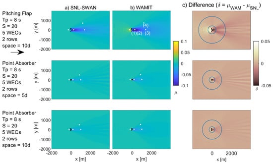
Figure 8.
WEC array wave field: (a) SNL-SWAN wave field, (b) WAMIT wave field, (c) difference wave field .
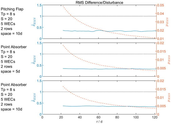
Figure 9.
WEC Array RMS difference/disturbance: normalized RMS difference, RMS disturbance, and plot of values over concentric circles as a function of radial distance.
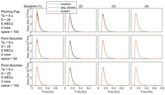
Figure 10.
WEC array spectra: plots of the omnidirectional wave spectra at the four points marked in the WAMIT wave field.
For the pitching flap case shown in Figure 8, Figure 9 and Figure 10, there is good agreement between the SNL-SWAN and WAMIT results, both quantitatively and qualitatively. The difference in quantitative metrics between WAMIT and SNL-SWAN is minimal, as demonstrated by and 30 d downwave and at 100 d. This demonstrates that for this real sea case, SNL-SWAN does a good job capturing the wave environment 30d from the WEC. This is further shown in Figure 10, where the spectral energy content is recovered by 30 d downwave.
For the point absorber case shown in Figure 8, Figure 9 and Figure 10, there is good agreement between the SNL-SWAN and WAMIT results, both quantitatively and qualitatively. The difference in quantitative metrics between WAMIT and SNL-SWAN is minimal, with and 30 d downwave and at 100 d. This demonstrates that for this real sea case, SNL-SWAN does a good job capturing the wave environment 30d from the WEC. This is further shown in Figure 10, where the difference in spectral energy content between the two codes is minimal by 30 d downwave.
7.2. Array Spacing
The section discusses results corresponding to the PA array cases with 5 d and 10 d spacing. The same real sea wave case is used, a BS spectrum, with s, and directional spreading of , listed in Table 5. For the point absorber case with 5d array spacing shown in Figure 8, Figure 9 and Figure 10, there is good agreement between the SNL-SWAN and WAMIT results, both quantitatively and qualitatively. There is not much of a qualitative difference between the wave field effects for the 5 and 10 d PA cases. The difference in quantitative metrics between WAMIT and SNL-SWAN is relatively small for the 5 d case, with and 30 d downwave and at 100 d. This demonstrates that for this real sea case, SNL-SWAN does a good job capturing the wave environment 30 d from the WEC with both 5 and 10 d spacing for the PA.
8. Conclusions
This results presented in this paper compared single WEC and WEC array wave fields produced by SNL-SWAN to those produced by the linear wave BEM code, WAMIT. Three WEC archetypes were considered: a pitching flap (PF), point absorber (PA), and hinged raft (HR). These WECs were selected to represent the breadth of existing WEC archetypes due to their varying size, power performance, and modes of motion. One objective of this work is to provide general guidance on modeling of WECs in spectral wave models, such as SNL-SWAN, independent of design archetypes. Wave conditions included wave periods representing short (4 s and 6 s), medium (8 s), and long (12 s) waves, in various spectral and directional spreading conditions. Comparisons were made qualitatively with detailed plots of the wave fields, and quantitatively by considering the root-mean-square difference between the wave fields normalized by the root-mean-square disturbance predicted in the WAMIT wave field. The study was carried out by first considering the single WEC comparison and then the WEC array cases. Conclusions are presented based on results observed from the single WEC cases and the WEC array cases, then overall conclusions are given.
8.1. Single WEC
The best agreement between SNL-SWAN and WAMIT occurred for higher directional spreading, and where the devices were tuned to absorb the most power. The worst comparisons occurred for lower directional spreading and longer waves relative to the device size. The directional spreading and power-absorption results were expected. Although, the longest waves showed the poorest fit, the overall WEC wave field disturbance was the smallest, and so inaccuracies may have less of an impact. Furthermore, the difference generally decreases further from the device, and nearly all cases show the difference in spectral energy content between the two codes is minimal by 500 m downwave.
8.2. WEC Array
Results showed that for the WEC array, in its best case, SNL-SWAN predicted the wave field over a circular arc at a radius 30 d with a difference of 20%, for an array of 5 point absorbers in two rows spaced at 10 d in an 8 s Bretschneider spectrum with a spreading, s = 20. In general, better agreement between SNL-SWAN and WAMIT occurred for longer waves relative to the device size; worse agreement occurred for shorter waves. Additionally, the WEC arrays cases had better agreement than the single WEC cases. For WEC arrays, the fit between SNL-SWAN and WAMIT differs the most in the near-field, and the overall impact of the array on the wave field decreased significantly with distance. This suggests that evaluating the performance of SNL-SWAN at a radial distance of roughly r = 30d is sufficient. The difference generally decreases further from the array, and nearly all cases show the difference in spectral energy content between the two codes is minimal by 30 d downwave.
Future work includes expanding upon this analysis to model larger WEC arrays and assessing the feasibility and importance of coupling of BEM models in the near-field, with a larger scale far-field SNL-SWAN model over varying depths.
8.3. Guidance
Based on the results of this numerical study, the authors recommend the following guidance when using SNL-SWAN (or other spectral-domain codes) to model wave field effects due to WECs:
- For arrays, SNL-SWAN shows differences of between 20% and 60% as compared to WAMIT, where the difference is normalized by the impact of the array on the wave field, which are between 1% and 5% at a distance of 30 characteristic diameters from the WECs;
- Directional wave spreading in the incident wave spectrum is important for SNL-SWAN accuracy; unidirectional waves are not modeled well;
- SNL-SWAN does not model wave reflection or scattering, which is a mechanism (in addition to power absorption) for the creation of a wave shadow. This causes larger errors in shorter waves. Preliminary results show the errors could be decreased by including reflections in SNL-SWAN;
- Truncating power absorption, because of RCW values greater than 1, worsens wave field modeling accuracy.
Author Contributions
Individual author contributions provided based on the CRediT taxonomy: Conceptualization, J.C.M., A.P., and K.R.; Methodology, J.C.M., A.P., and K.R.; Software, J.C.M., A.P., and K.R.; Validation, J.C.M., and A.P.; Formal Analysis, J.C.M. and A.P.; Investigation, J.C.M. and A.P.; Resources, J.C.M., A.P., and K.R.; Data Curation, J.C.M. and A.P.; Writing—Original Draft, J.C.M., A.P., and K.R.; Writing—Review and Editing, J.C.M., A.P., and K.R.; Visualization, J.C.M.; Supervision, K.R.; Project Administration, K.R.; Funding Acquisition, K.R. All authors have read and agreed to the published version of the manuscript.
Funding
Funding for this work was provided by the U.S. Department of Energy, Office of Energy Efficiency and Renewable Energy, Water Power Technologies Office. Sandia National Laboratories is a multimission laboratory managed and operated by National Technology & Engineering Solutions of Sandia, LLC, a wholly owned subsidiary of Honeywell International Inc., for the U.S. Department of Energy’s National Nuclear Security Administration under contract DE-NA0003525. This paper describes objective technical results and analysis. Any subjective views or opinions that might be expressed in the paper do not necessarily represent the views of the U.S. Department of Energy or the United States Government.
Acknowledgments
The authors would like to acknowledge the following people for their contributions to this work: Jesse Roberts, Chris Chartrand, and Sterling Olson at Sandia National Laboratories.
Conflicts of Interest
The authors declare no conflict of interest. The funders had no role in the design of the study; in the collection, analyses, or interpretation of data; in the writing of the manuscript, or in the decision to publish the results.
References
- Folley, M. Numerical Modelling of Wave Energy Converters: State-of-the-Art Techniques for Single Devices and Arrays, 1st ed.; Elsevier: Amsterdam, The Netherlands, 2016. [Google Scholar]
- Lee, C.-H.; Newman, J.N. WAMIT 2017. WAMIT Software. Available online: http://www.wamit.com/ (accessed on 1 December 2019).
- Babarit, A. NEMOH 2017. NEMOH Software. Available online: https://lheea.ec-nantes.fr/logiciels-et-brevets/nemoh-presentation-192863.kjsp?RH=1489859622433 (accessed on 1 December 2019).
- Cummins, W.E. The Impulse Response Function and Ship Motions. 1962. Available online: https://books.google.com/books?id=GLLANwAACAAJ (accessed on 1 December 2019).
- TELEMAC. TOMAWAC 2017. TOMAWAC Software. Available online: http://www.opentelemac.org/index.php/modules-list/20-tomawac/ (accessed on 1 December 2019).
- TU Delft. SWAN 2019. SWAN (Simulating WAves Nearshore) Code. Available online: http://swanmodel.sourceforge.net/ (accessed on 1 December 2019).
- Millar, D.; Smith, H.; Reeve, D. Modelling analysis of the sensitivity of shoreline change to a wave farm. Ocean. Eng. 2007, 34, 884–901. [Google Scholar] [CrossRef]
- Smith, H.C.; Pearce, C.; Millar, D.L. Further analysis of change in nearshore wave climate due to an offshore wave farm: An enhanced case study for the Wave Hub site. Renew. Energy 2011, 40, 51–64. [Google Scholar] [CrossRef]
- Silverthorne, K.E.; Folley, M. A New Numerical Representation of Wave Energy Converters in a Spectral Wave Model. In Proceedings of the 9th European Wave and Tidal Energy Conference, Southampton, UK, 5–9 September 2011. [Google Scholar]
- Haller, M.C.; Porter, A.; Lenee-Bluhm, P.; Rhinefrank, K.; Hammagren, E.; Özkan Haller, T.; Newborn, D. Laboratory Observation of Waves in the Vicinity of WEC-Arrays. In Proceedings of the 9th European Wave and Tidal Energy Conference, Southampton, UK, 5–9 September 2011. [Google Scholar]
- Porter, A. Laboratory Observations and Numerical Modeling of the Effects of an Array of Wave Energy Converters. Master’s Thesis, Oregon State University, Corvallis, OR, USA, 2012. [Google Scholar]
- McNatt, J.C. Wave Field Patterns Generated by Wave Energy Converters. Master’s Thesis, Oregon State University, Corvallis, OR, USA, 2012. [Google Scholar]
- Rusu, E.; Onea, F. Study on the influence of the distance to shore for a wave energy farm operating in the central part of the Portuguese nearshore. Energy Convers. Manag. 2016, 114, 209–223. [Google Scholar] [CrossRef]
- Greenwood, C.; Christie, D.; Venugopal, V.; Morrison, J.; Vogler, A. Modelling performance of a small array of Wave Energy Converters: Comparison of Spectral and Boussinesq models. Energy 2016, 113, 258–266. [Google Scholar] [CrossRef]
- Venugopal, V.; Nemalidinne, R.; Vögler, A. Numerical modelling of wave energy resources and assessment of wave energy extraction by large scale wave farms. Ocean. Coast. Manag. 2017, 147, 37–48. [Google Scholar] [CrossRef]
- SNL-SWAN, 2019. SNL-SWAN (Sandia National Laboratories Simulating WAves Nearshore) Software. Available online: https://github.com/SNL-WaterPower/SNL-SWAN (accessed on 1 December 2019).
- Chang, G.; Ruehl, K.; Jones, C.A.; Roberts, J.; Chartrand, C. Numerical modeling of the effects of wave energy converter characteristics on nearshore wave conditions. Renew. Energy 2015, 89, 636–648. [Google Scholar] [CrossRef]
- Roberts, J.; Jones, C. Marine Renewable Energy Sediment Stability Evaluation Framework. In Proceedings of the 11th European Wave and Tidal Energy Conference, Nantes, France, 6–11 September 2015. [Google Scholar]
- Ruehl, K.; Porter, A.; Posner, A.; Roberts, J. Development of SNL-SWAN, a Validated Wave Energy Converter Array Modeling Tool. In Proceedings of the 10th European Wave and Tidal Energy Conference, Aalborg, Denmark, 2–5 December 2013. [Google Scholar]
- McNatt, J.C.; Porter, A.; Ruehl, K.; Roberts, J. Verification of the SNL-SWAN Spectral WEC-wave Model with Phase-resolved Linear Wave Fields. In Proceedings of the 12th European Wave and Tidal Energy Conference, Cork, Ireland, 27 August–1 September 2017. [Google Scholar]
- Dallman, A.R.; Neary, V.S. Characterization of U.S. Wave Energy Converter (WEC) Test Sites: A Catalogue of Met-Ocean Data; SAND2014-18206; Sandia National Laboratories: Albuquerque, NM, USA, 2014. [CrossRef]
- Chakrabarti, S.K. Hydrodynamics of Offshore Structures; Google-Books-ID: RNGW9CucxQsC; WIT Press: New Forest, UK, 1987. [Google Scholar]
© 2020 by the authors. Licensee MDPI, Basel, Switzerland. This article is an open access article distributed under the terms and conditions of the Creative Commons Attribution (CC BY) license (http://creativecommons.org/licenses/by/4.0/).