
Design and Testing of an Autonomous Navigation Unmanned Surface Vehicle for Buoy Inspection


Abstract
1. Introduction
2. USV Hardware Composition and Navigation
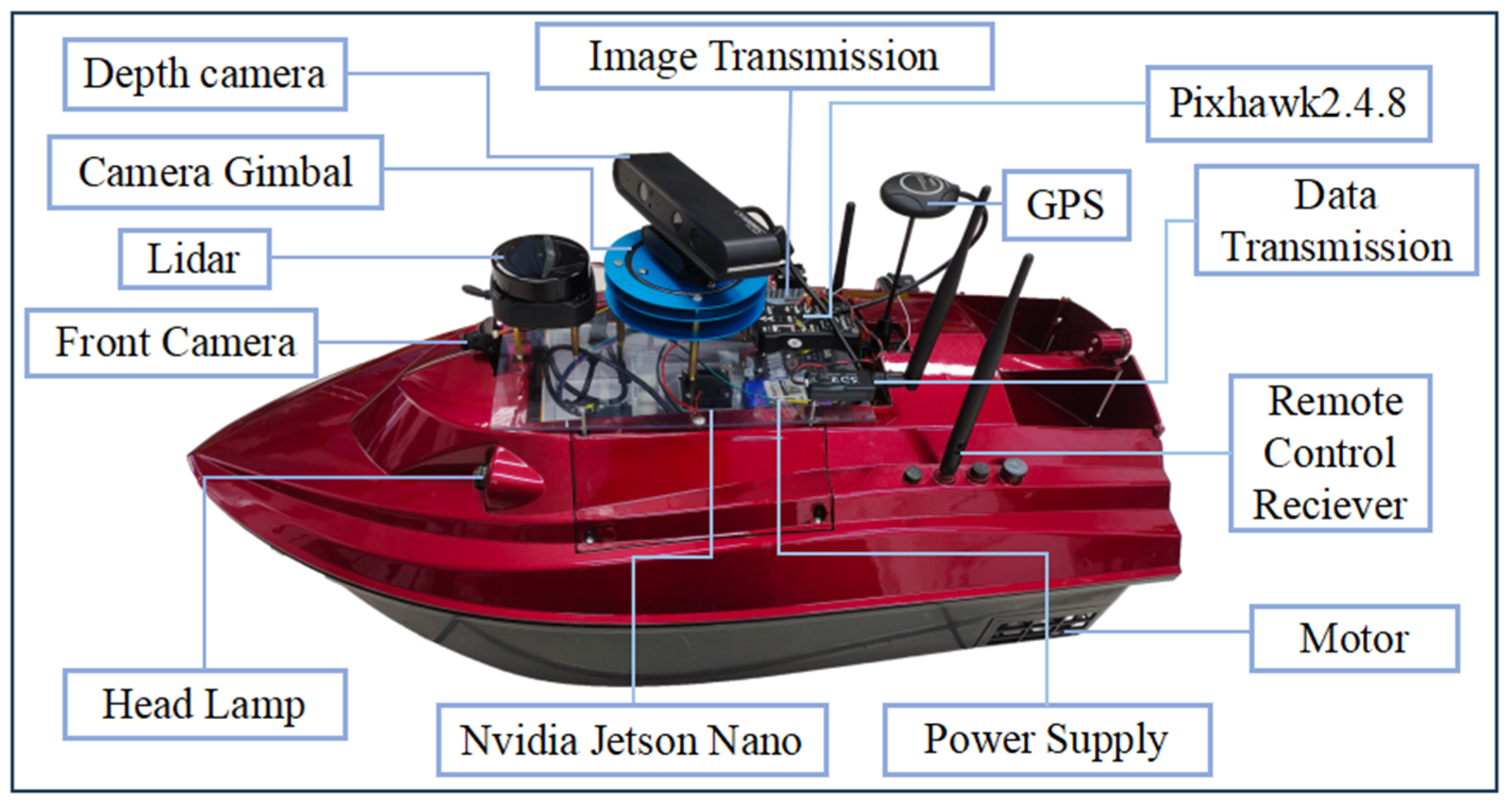
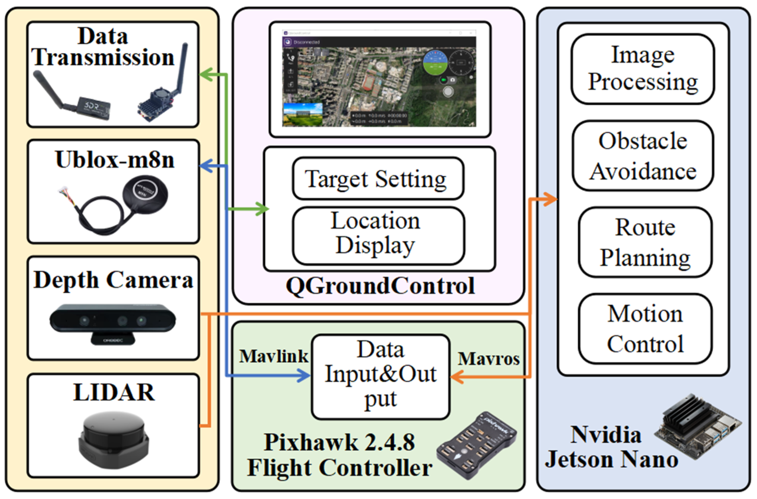
2.1. USV Hardware Composition
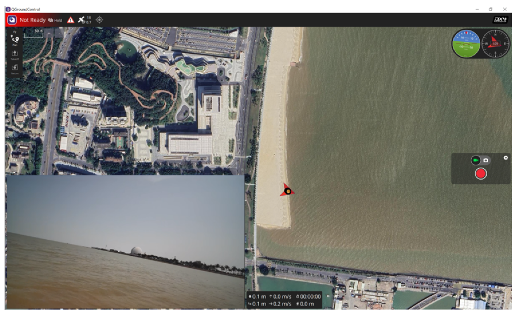
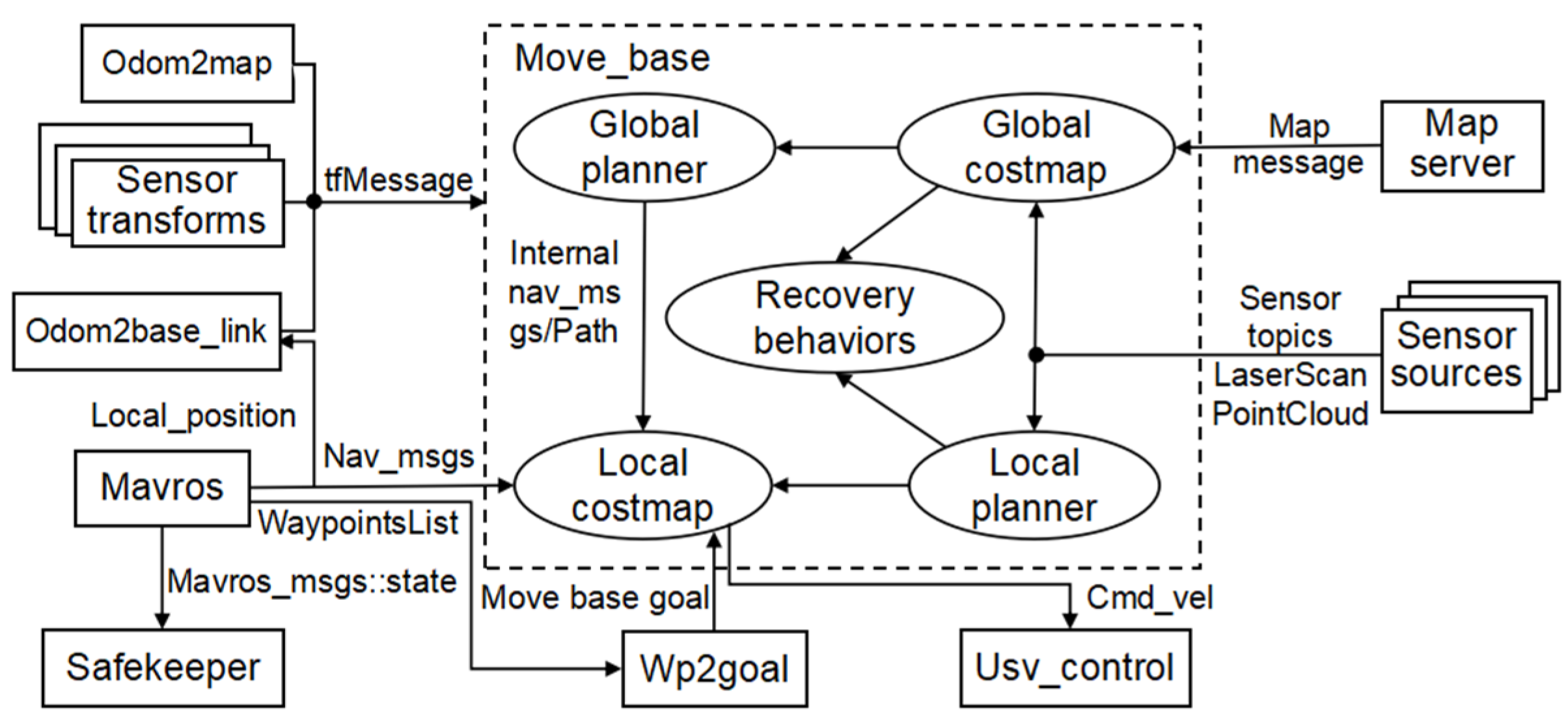
2.2. Implementation of USV Navigation Based on ROS
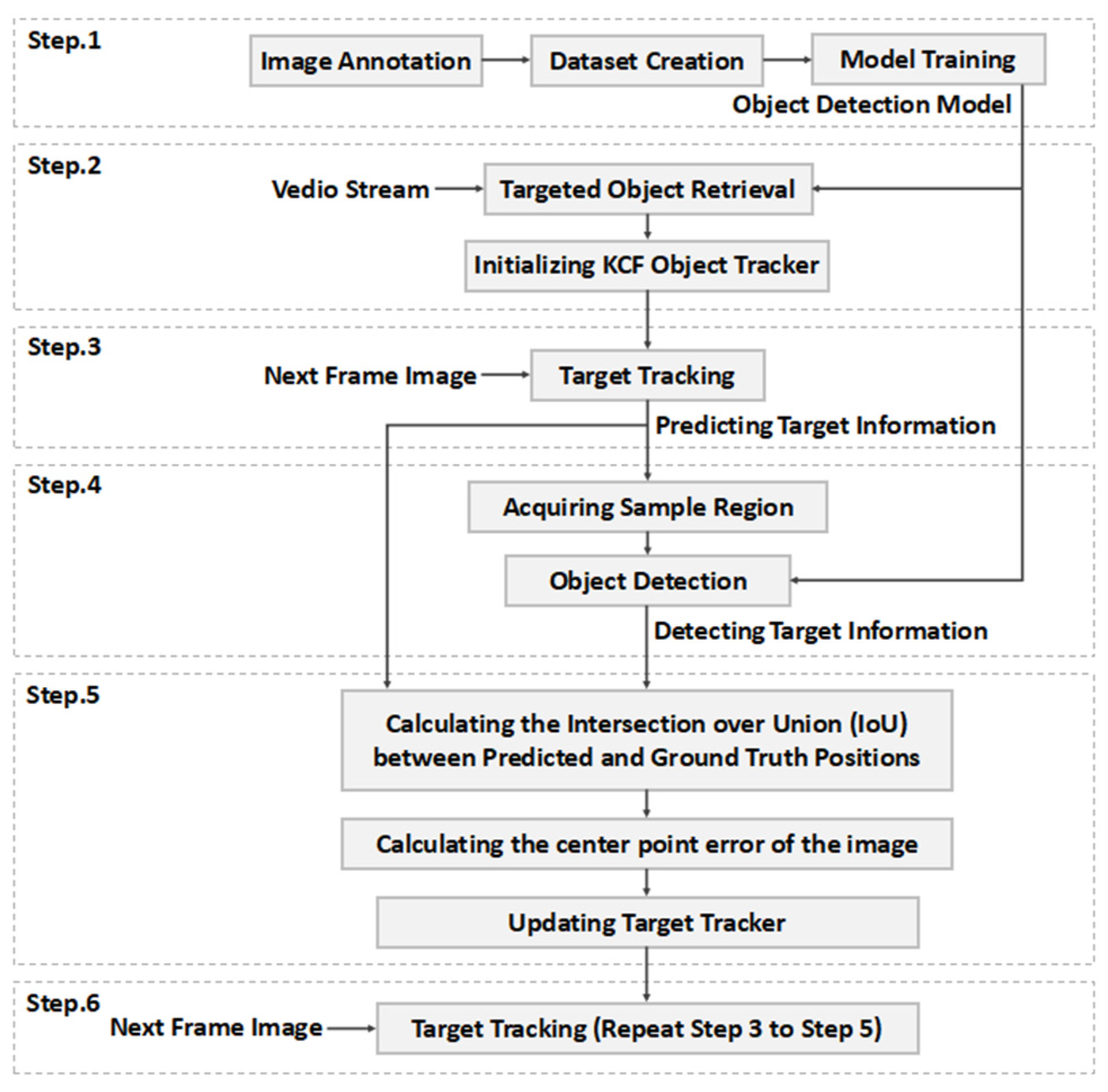
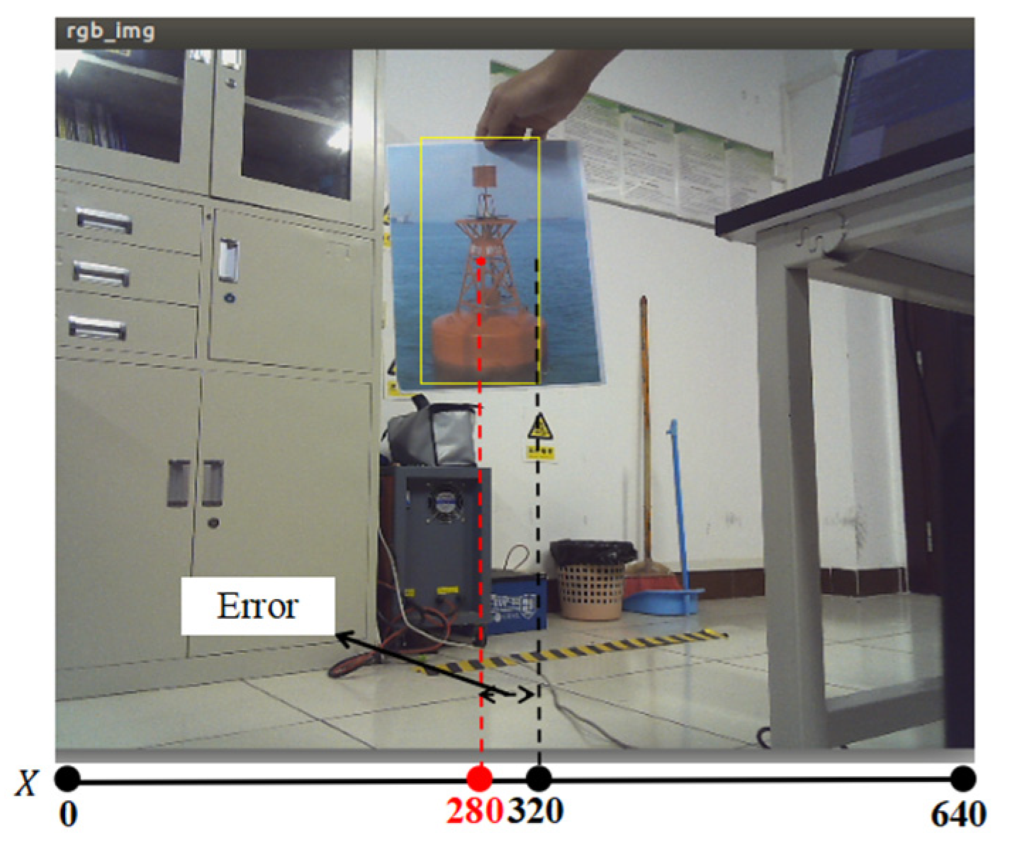
2.3. Image Tracking System Based on the KCF Object Tracking Algorithm
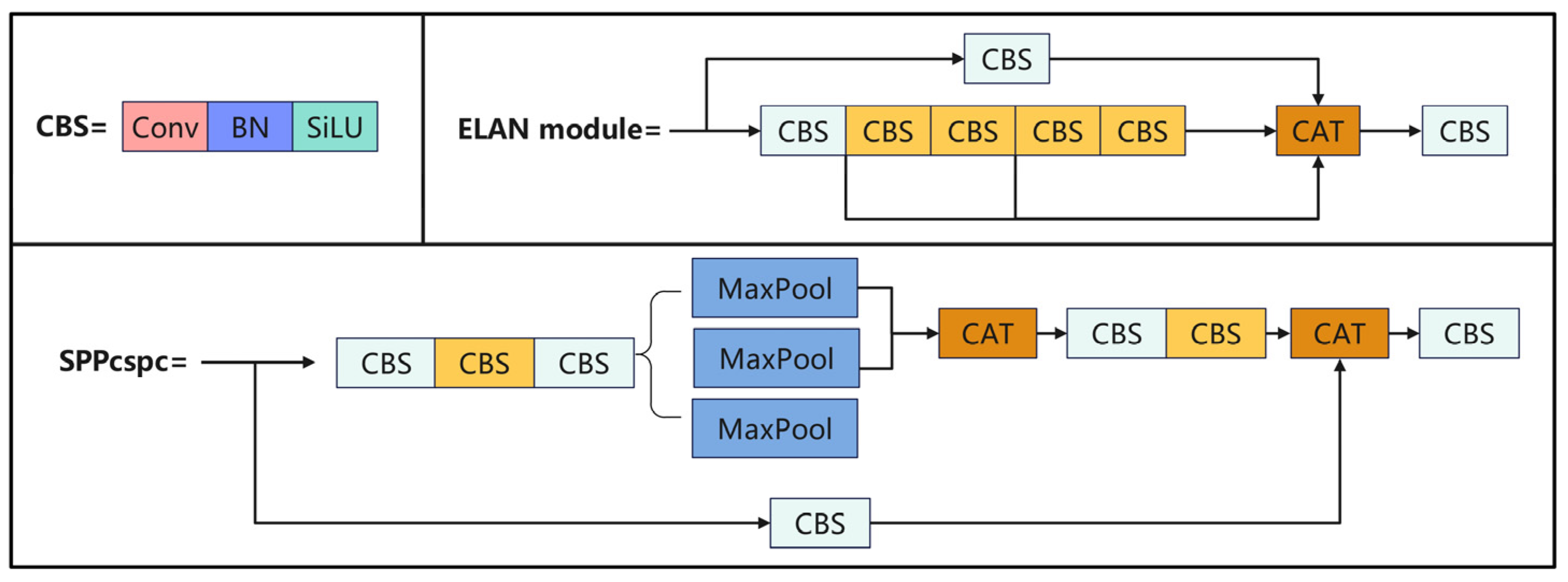
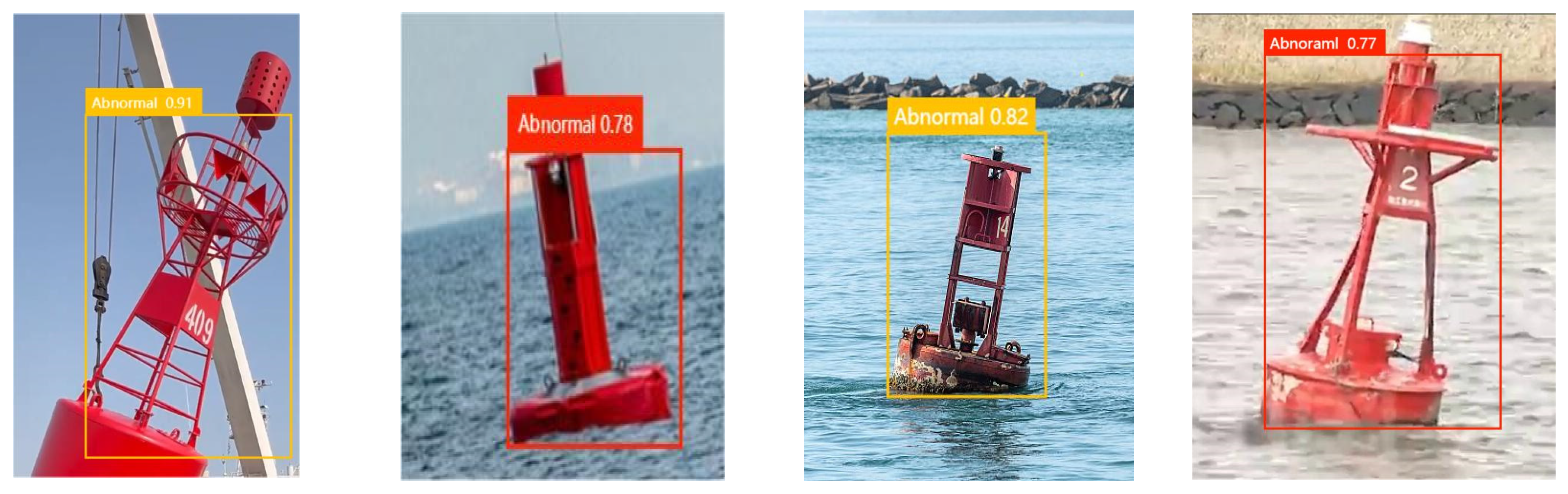
3. Buoy Target Detection Algorithm Based on YOLOv7
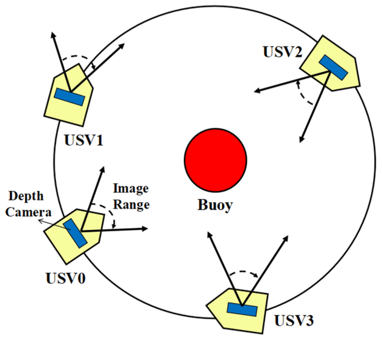
4. USV Circumnavigation Control Algorithms for Buoy Inspection
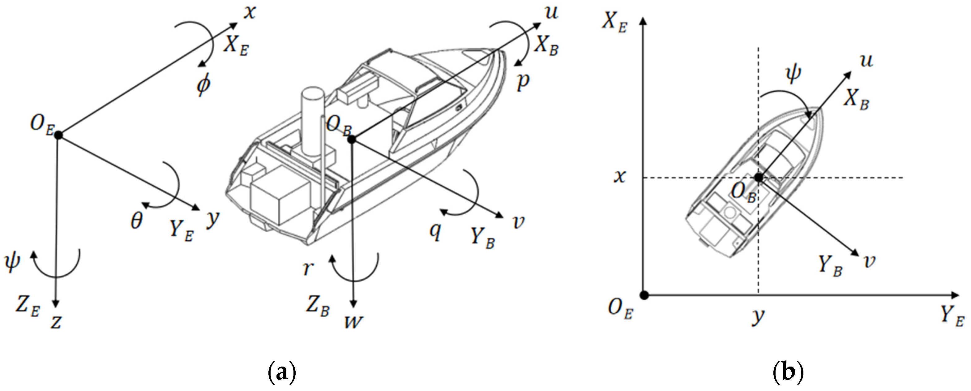
4.1. Mathematical Model of Kinematics and Dynamics for USV
- Neglecting the movements associated with heave, pitch, and roll degrees of freedom, the unmanned vessel’s locomotion is confined to the horizontal plane, .
- The mass distribution of the USV is uniform, with the vessel’s hull exhibiting bilateral symmetry about both its longitudinal and transverse axes. Furthermore, the vessel’s center of gravity coincides with the origin of the attached body coordinate system, aligning with the principal axes in the direction towards the bow, starboard side, and vertically downwards towards the center of the Earth.
- The dynamics model neglects higher-order hydrodynamic terms and the off-diagonal elements within the damping matrix.
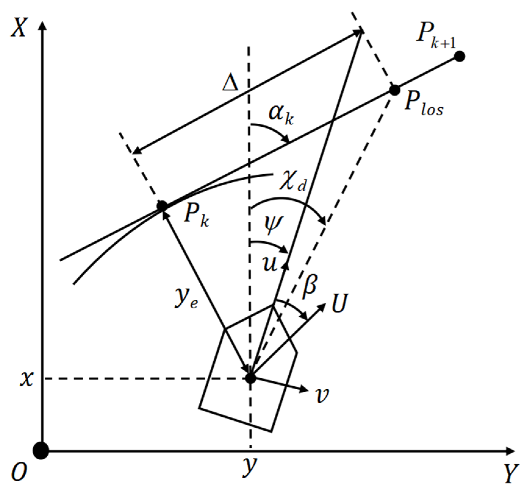
4.2. Line-of-Sight (LOS) Guidance Principles
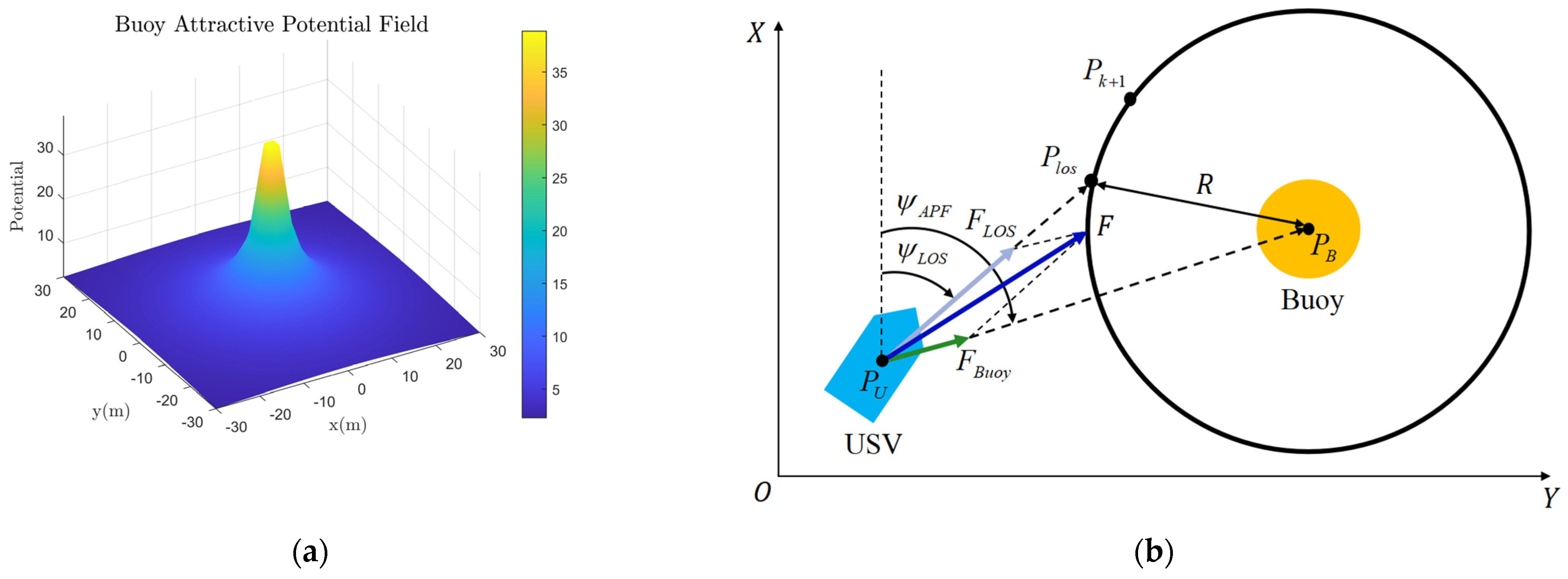
4.3. USV Circumnavigation Control Algorithms
5. Experiments and Discussion
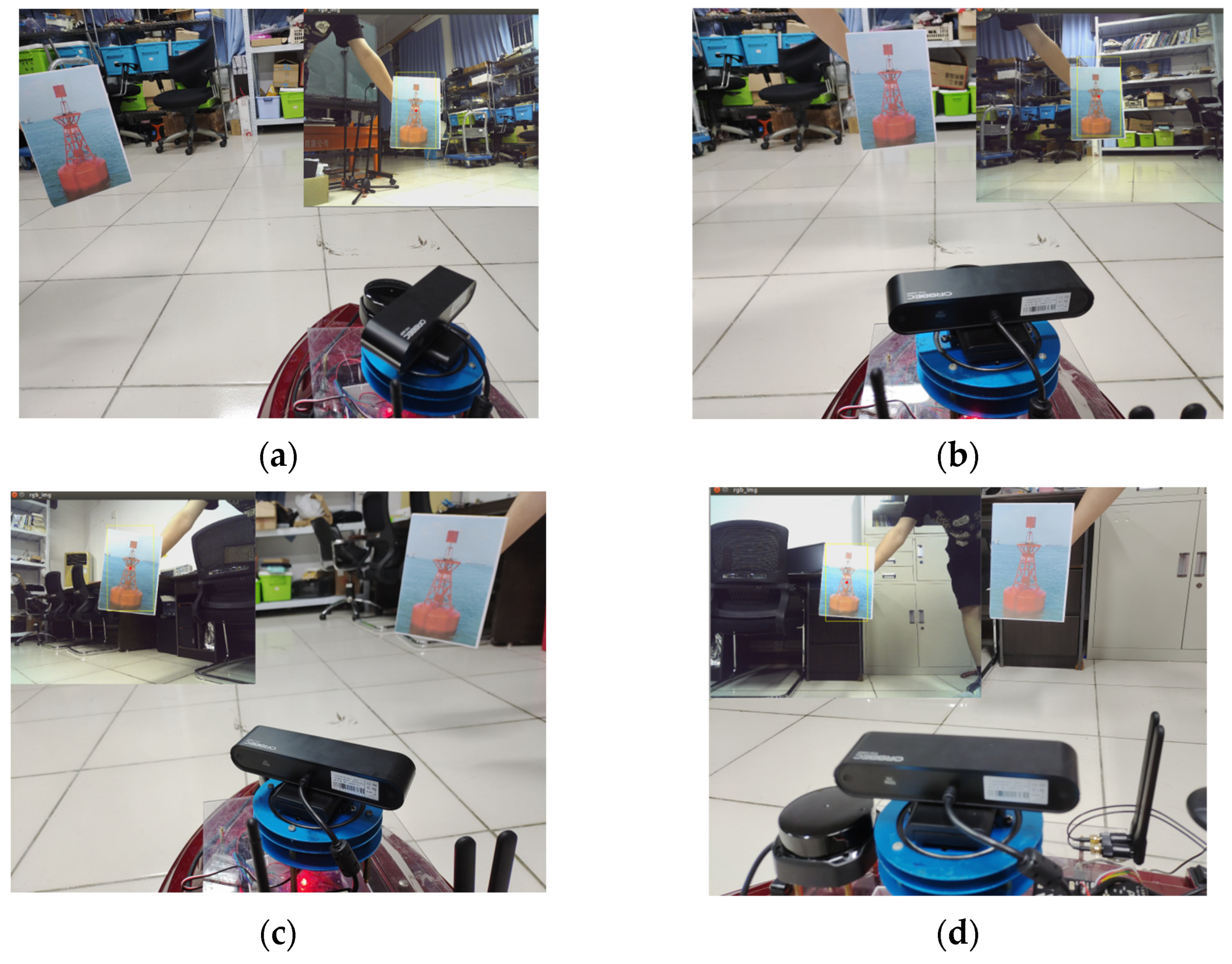
5.1. Buoy Image Tracking Experiment
5.2. Buoy Detection Algorithm Based on YOLOv7 Experiment
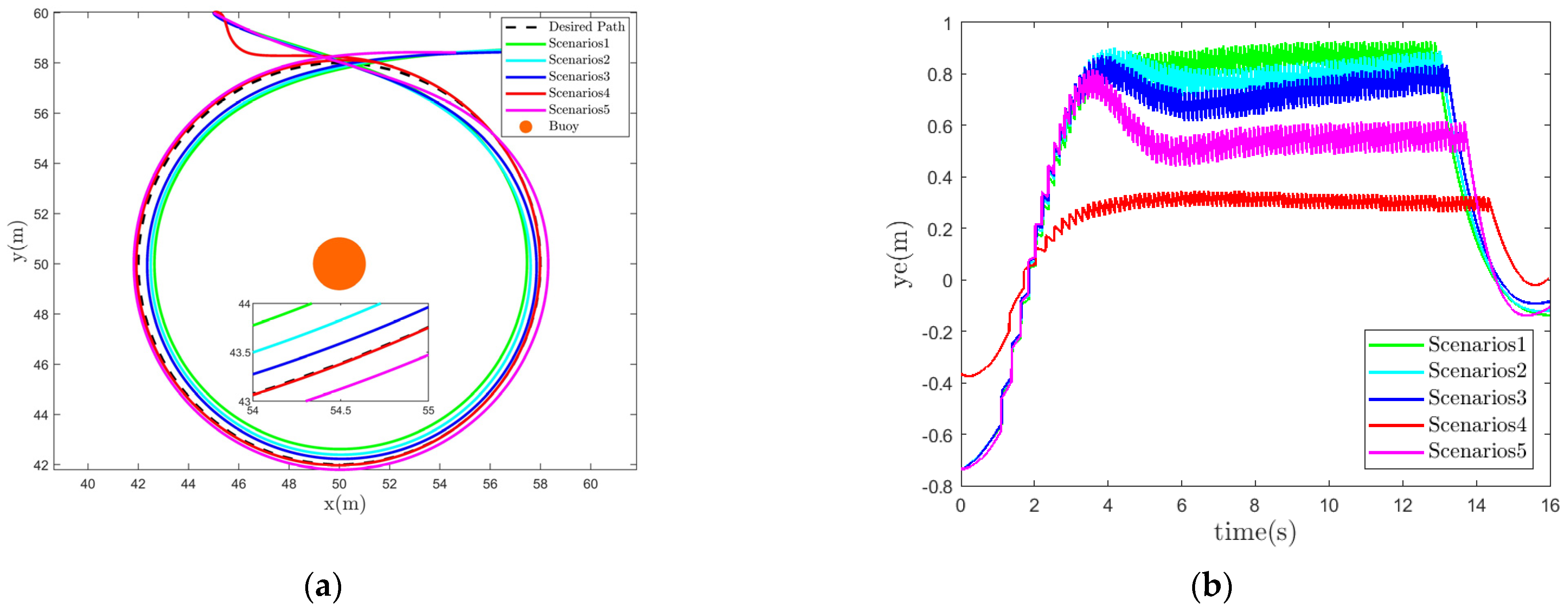
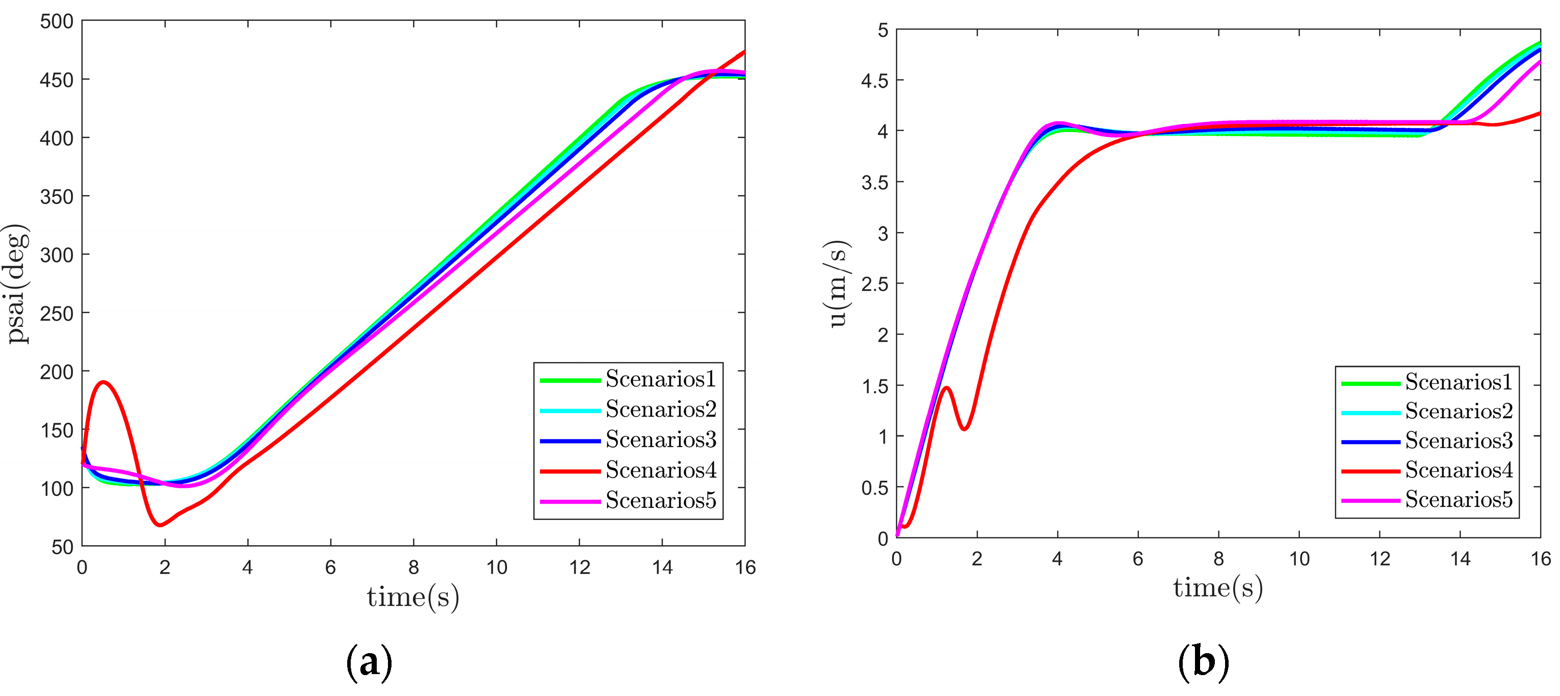
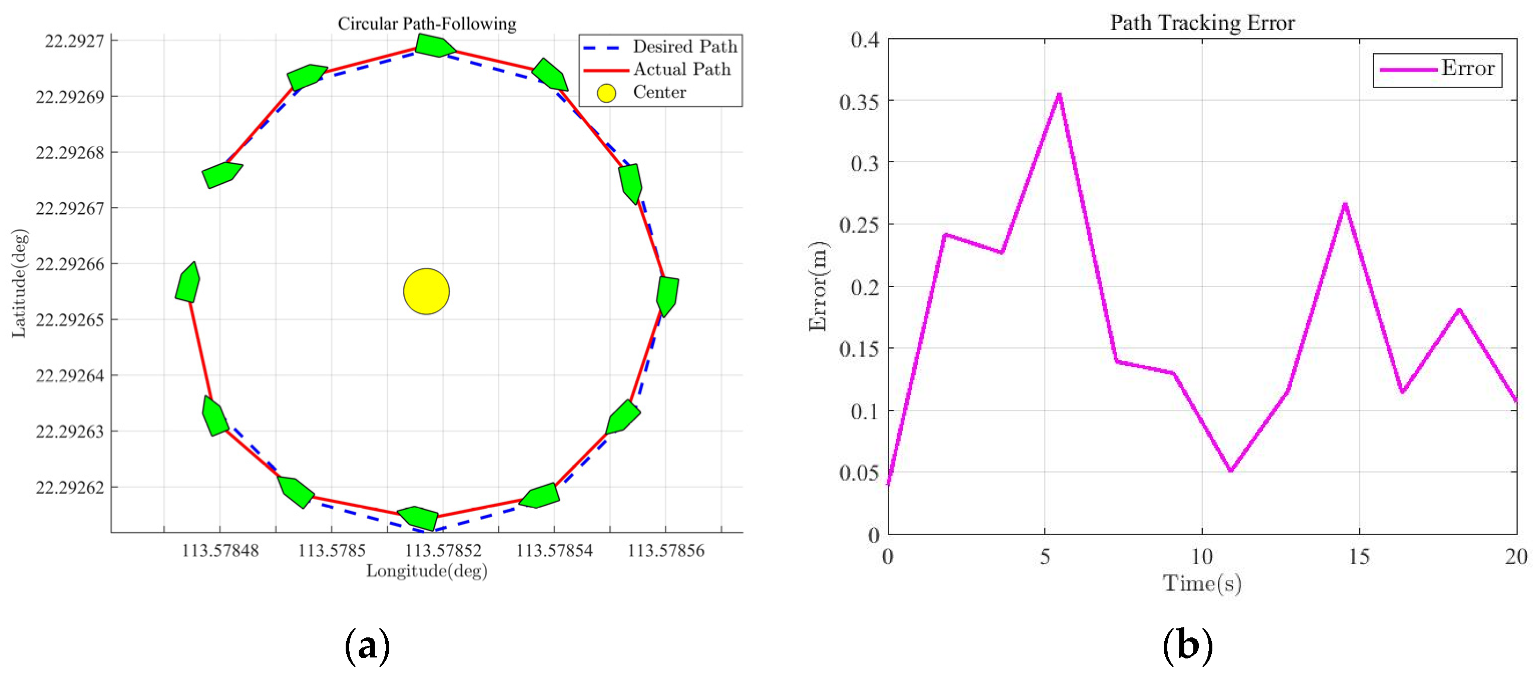
5.3. Buoy Circumnavigation Control Algorithm Experiment
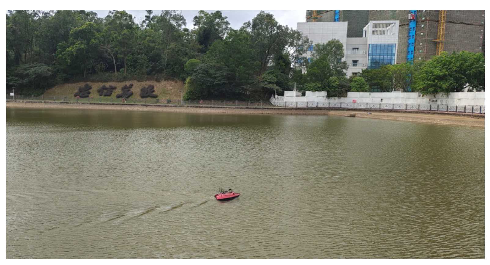
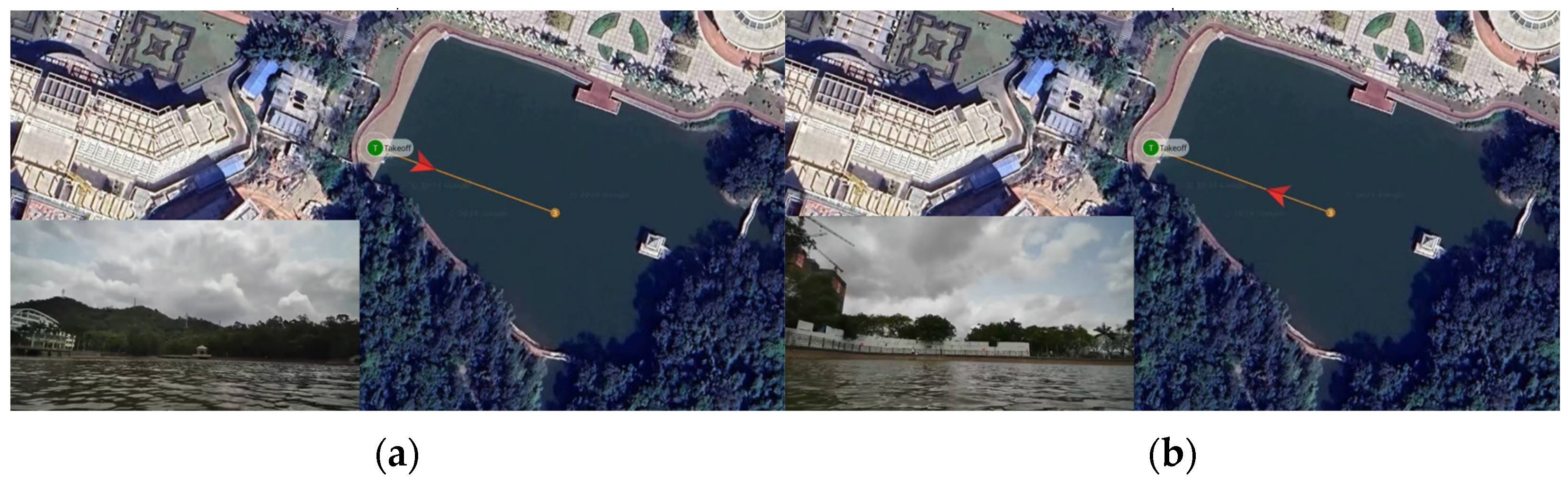
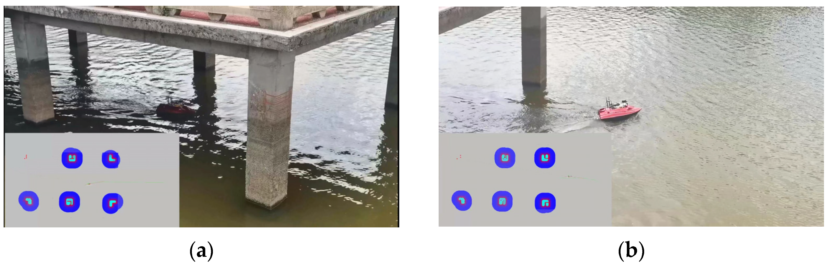
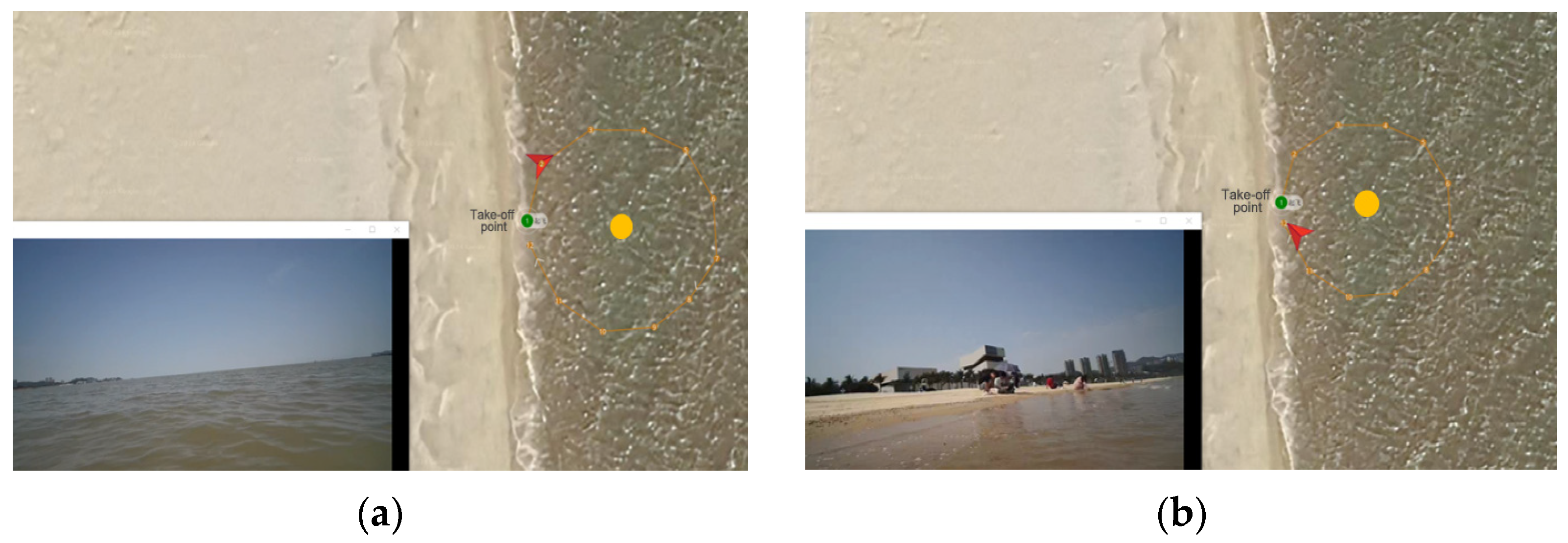
5.4. USV Field Test Experiment
6. Conclusions
Author Contributions
Funding
Institutional Review Board Statement
Informed Consent Statement
Data Availability Statement
Conflicts of Interest
References
- Hasbullah, M.I.; Osnin, N.A.; Mohd Salleh, N.H. A Systematic Review and Meta-Analysis on the Development of Aids to Navigation. Aust. J. Marit. Ocean Aff. 2023, 15, 247–267. [Google Scholar] [CrossRef]
- Turner, N.M. Traditional Aids to Navigation: The next 25 Years. J. Navig. 1997, 50, 234–241. [Google Scholar] [CrossRef]
- MahmoudZadeh, S.; Yazdani, A. A Cooperative Fault-Tolerant Mission Planner System for Unmanned Surface Vehicles in Ocean Sensor Network Monitoring and Inspection. IEEE Trans. Veh. Technol. 2023, 72, 1101–1115. [Google Scholar] [CrossRef]
- Li, B.; Gao, S.; Li, C.; Wan, H. Maritime Buoyage Inspection System Based on an Unmanned Aerial Vehicle and Active Disturbance Rejection Control. IEEE Access 2021, 9, 22883–22893. [Google Scholar] [CrossRef]
- Trasviña-Moreno, C.A.; Blasco, R.; Marco, Á.; Casas, R.; Trasviña-Castro, A. Unmanned Aerial Vehicle Based Wireless Sensor Network for Marine-Coastal Environment Monitoring. Sensors 2017, 17, 460. [Google Scholar] [CrossRef]
- Lomax, A.S.; Corso, W.; Etro, J.F. Employing Unmanned Aerial Vehicles (UAVs) as an Element of the Integrated Ocean Observing System. In Proceedings of the Proceedings of OCEANS 2005 MTS/IEEE, Washington, DC, USA, 17–23 September 2006. [Google Scholar]
- Jin, J.-Y.; Dae Do, J.; Park, J.-S.; Park, J.S.; Lee, B.; Hong, S.-D.; Moon, S.-J.; Hwang, K.C.; Chang, Y.S. Intelligent Buoy System (INBUS): Automatic Lifting Observation System for Macrotidal Coastal Waters. Front. Mar. Sci. 2021, 8, 668673. [Google Scholar] [CrossRef]
- Xin, M.; Yang, F.; Liu, H.; Shi, B.; Zhang, K.; Zhai, M. Single-Difference Dynamic Positioning Method for GNSS-Acoustic Intelligent Buoys Systems. J. Navig. 2020, 73, 646–657. [Google Scholar] [CrossRef]
- Zhang, D.; Ashraf, M.A.; Liu, Z.; Peng, W.-X.; Golkar, M.J.; Mosavi, A. Dynamic Modeling and Adaptive Controlling in GPS-Intelligent Buoy (GIB) Systems Based on Neural-Fuzzy Networks. Ad Hoc. Netw. 2020, 103, 102149. [Google Scholar] [CrossRef]
- Yuan, S.; Li, Y.; Bao, F.; Xu, H.; Yang, Y.; Yan, Q.; Zhong, S.; Yin, H.; Xu, J.; Huang, Z.; et al. Marine Environmental Monitoring with Unmanned Vehicle Platforms: Present Applications and Future Prospects. Sci. Total Environ. 2023, 858, 159741. [Google Scholar] [CrossRef]
- de Sousa, J.B.; Andrade Gonçalves, G. Unmanned Vehicles for Environmental Data Collection. Clean Technol. Environ. Policy 2011, 13, 369–380. [Google Scholar] [CrossRef]
- Xiong, Y.; Zhu, H.; Pan, L.; Wang, J. Research on Intelligent Trajectory Control Method of Water Quality Testing Unmanned Surface Vessel. J. Mar. Sci. Eng. 2022, 10, 1252. [Google Scholar] [CrossRef]
- Sotelo-Torres, F.; Alvarez, L.V.; Roberts, R.C. An Unmanned Surface Vehicle (USV): Development of an Autonomous Boat with a Sensor Integration System for Bathymetric Surveys. Sensors 2023, 23, 4420. [Google Scholar] [CrossRef] [PubMed]
- Cheng, L.; Deng, B.; Yang, Y.; Lyu, J.; Zhao, J.; Zhou, K.; Yang, C.; Wang, L.; Yang, S.; He, Y. Water Target Recognition Method and Application for Unmanned Surface Vessels. IEEE Access 2022, 10, 421–434. [Google Scholar] [CrossRef]
- Kim, Y.; Ryou, J. A Study of Sonar Image Stabilization of Unmanned Surface Vehicle Based on Motion Sensor for Inspection of Underwater Infrastructure. Remote Sens. 2020, 12, 3481. [Google Scholar] [CrossRef]
- Zhou, Y.; Yang, W.; Shen, Y. Scale-Adaptive KCF Mixed with Deep Feature for Pedestrian Tracking. Electronics 2021, 10, 536. [Google Scholar] [CrossRef]
- Liu, K.; Tang, H.; He, S.; Yu, Q.; Xiong, Y.; Wang, N. Performance Validation of Yolo Variants for Object Detection. In Proceedings of the 2021 International Conference on Bioinformatics and Intelligent Computing, Harbin, China, 22–24 January 2021; ACM: New York, NY, USA, 2021. [Google Scholar]
- Liu, W.; Anguelov, D.; Erhan, D.; Szegedy, C.; Reed, S.; Fu, C.-Y.; Berg, A.C. SSD: Single Shot MultiBox Detector. In Proceedings of the Computer Vision—ECCV 2016, Amsterdam, The Netherlands, 11–14 October 2016; Springer International Publishing: Cham, Switzerland, 2016; pp. 21–37. [Google Scholar]
- Wang, C.-Y.; Bochkovskiy, A.; Liao, H.-Y.M. YOLOv7: Trainable Bag-of-Freebies Sets New State-of-the-Art for Real-Time Object Detectors. In Proceedings of the 2023 IEEE/CVF Conference on Computer Vision and Pattern Recognition (CVPR), Vancouver, BC, Canada, 17–24 June 2023. [Google Scholar]
- Zhou, X.; Ding, W.; Jin, W. Microwave-Assisted Extraction of Lipids, Carotenoids, and Other Compounds from Marine Resources. In Innovative and Emerging Technologies in the Bio-Marine Food Sector; Elsevier: Amsterdam, The Netherlands, 2022; pp. 375–394. [Google Scholar]
- Liu, Y.; Anderlini, E.; Wang, S.; Ma, S.; Ding, Z. Ocean Explorations Using Autonomy: Technologies, Strategies and Applications. In Offshore Robotics; Springer: Singapore, 2022; pp. 35–58. [Google Scholar]
- Pan, M.; Liu, Y.; Cao, J.; Li, Y.; Li, C.; Chen, C.-H. Visual Recognition Based on Deep Learning for Navigation Mark Classification. IEEE Access 2020, 8, 32767–32775. [Google Scholar] [CrossRef]
- Ding, X.; Hao, T.; Tan, J.; Liu, J.; Han, J.; Guo, Y.; Ding, G. ResRep: Lossless CNN Pruning via Decoupling Remembering and Forgetting. In Proceedings of the 2021 IEEE/CVF International Conference on Computer Vision (ICCV), Montreal, QC, Canada, 11–17 October 2021. [Google Scholar]
- McCue, L. Handbook of Marine Craft Hydrodynamics and Motion Control [Bookshelf]. IEEE Control Syst. 2016, 36, 78–79. [Google Scholar]
- Skjetne, R.; Smogeli, Ø.; Fossen, T.I. Modeling, Identification, and Adaptive Maneuvering of CyberShip II: A Complete Design with Experiments. IFAC Proc. Vol. 2004, 37, 203–208. [Google Scholar] [CrossRef]
- Ding, X.; Zhang, X.; Ma, N.; Han, J.; Ding, G.; Sun, J. RepVGG: Making VGG-Style ConvNets Great Again. In Proceedings of the 2021 IEEE/CVF Conference on Computer Vision and Pattern Recognition (CVPR), Nashville, TN, USA, 20–25 June 2021. [Google Scholar]
- Fossen, T.I.; Breivik, M.; Skjetne, R. Line-of-Sight Path Following of Underactuated Marine Craft. IFAC Proc. Vol. 2003, 36, 211–216. [Google Scholar] [CrossRef]
- Xu, H.; Guedes Soares, C. Review of Path-Following Control Systems for Maritime Autonomous Surface Ships. J. Mar. Sci. Appl. 2023, 22, 153–171. [Google Scholar] [CrossRef]
- Moe, S.; Pettersen, K.Y.; Fossen, T.I.; Gravdahl, J.T. Line-of-Sight Curved Path Following for Underactuated USVs and AUVs in the Horizontal Plane under the Influence of Ocean Currents. In Proceedings of the 2016 24th Mediterranean Conference on Control and Automation (MED), Athens, Greece, 21–24 June 2016. [Google Scholar]
- Khatib, O. Real-Time Obstacle Avoidance for Manipulators and Mobile Robots. Int. J. Rob. Res. 1986, 5, 90–98. [Google Scholar] [CrossRef]
- Bradley, A.V.; Gomez-Uribe, C.A.; Vuyyuru, M.R. Shift-Curvature, SGD, and Generalization. Mach. Learn. Sci. Technol. 2022, 3, 045002. [Google Scholar] [CrossRef]


| Title | Parameter | Title | Parameter |
|---|---|---|---|
| Length | 1.2 m | Motor Power | 1700 w |
| Width | 50 cm | Load Capacity | 5 kg |
| Height | 35 cm | Propeller Diameter | 6 cm |
| Speed | 5 m/s(max) | Draft | 10 cm |
| Weight Battery Capacity | 20 kg 15.6 Ah/173.2 Wh | Wave Resistance Grade Battery Duration | Level 4, 1.5 m Waves 4 h |
| Hardware | Title | Parameter |
|---|---|---|
| Data Transmission | transmission distance | 30 km |
| Ublox-m8n | positioning accuracy | 5 kg |
| Depth Camera | working range | 0.6–8 m |
| Lidar | measuring radius | 18 m |
| Method | FPS | mAP@0.5% | Params(M) |
|---|---|---|---|
| YOLOv3 | 53 | 81.4 | 61.53 |
| YOLOv4 | 55 | 80.6 | 52.5 |
| YOLOv5 | 86 | 84.6 | 20.9 |
| YOLOv7 | 99 | 91.8 | 36.39 |
| Hydrodynamic Parameters | ||
| kg | kg | kg |
| kg | kg/s | kg·m2/s |
| Scenarios | (m) | u (m/s) | ||
|---|---|---|---|---|
| 1 | 0.2 | 0.8 | 2.4 | 1 |
| 2 | 0.4 | 0.6 | 2.4 | 1 |
| 3 | 0.6 | 0.4 | 2.4 | 1 |
| 4 | 0.8 | 0.2 | 2.4 | 1 |
| 5 | 1 | 0 | 2.4 | 1 |
Disclaimer/Publisher’s Note: The statements, opinions and data contained in all publications are solely those of the individual author(s) and contributor(s) and not of MDPI and/or the editor(s). MDPI and/or the editor(s) disclaim responsibility for any injury to people or property resulting from any ideas, methods, instructions or products referred to in the content. |
© 2024 by the authors. Licensee MDPI, Basel, Switzerland. This article is an open access article distributed under the terms and conditions of the Creative Commons Attribution (CC BY) license (https://creativecommons.org/licenses/by/4.0/).
Share and Cite
Lu, Z.; Li, W.; Zhang, X.; Wang, J.; Zhuang, Z.; Liu, C. Design and Testing of an Autonomous Navigation Unmanned Surface Vehicle for Buoy Inspection. J. Mar. Sci. Eng. 2024, 12, 819. https://doi.org/10.3390/jmse12050819
Lu Z, Li W, Zhang X, Wang J, Zhuang Z, Liu C. Design and Testing of an Autonomous Navigation Unmanned Surface Vehicle for Buoy Inspection. Journal of Marine Science and Engineering. 2024; 12(5):819. https://doi.org/10.3390/jmse12050819
Chicago/Turabian StyleLu, Zhiqiang, Weihua Li, Xinzheng Zhang, Jianhui Wang, Zihao Zhuang, and Cheng Liu. 2024. "Design and Testing of an Autonomous Navigation Unmanned Surface Vehicle for Buoy Inspection" Journal of Marine Science and Engineering 12, no. 5: 819. https://doi.org/10.3390/jmse12050819
APA StyleLu, Z., Li, W., Zhang, X., Wang, J., Zhuang, Z., & Liu, C. (2024). Design and Testing of an Autonomous Navigation Unmanned Surface Vehicle for Buoy Inspection. Journal of Marine Science and Engineering, 12(5), 819. https://doi.org/10.3390/jmse12050819