Article

Energy-Efficient Resource Optimization for IRS-Assisted VLC-Enabled Offshore Communication System

College of Information Engineering, Shanghai Maritime University, Shanghai 201306, China
*
Author to whom correspondence should be addressed.
J. Mar. Sci. Eng. 2024, 12(5), 772; https://doi.org/10.3390/jmse12050772
Submission received: 10 April 2024 / Revised: 26 April 2024 / Accepted: 5 May 2024 / Published: 5 May 2024

Abstract

:
In this paper, a downlink energy efficiency maximization problem is investigated in an intelligent reflective surface (IRS)-assisted visible light communication system. In order to extend wireless communication coverage of the onshore base station, an IRS mounted on a unmanned aerial vehicle (UAV) is introduced to assist an onshore lighthouse with simultaneously providing remote ship users wireless communication services and illumination. Aiming to maximizing the energy efficiency of the proposed system, a resource allocation problem is formulated as the ratio of the achievable system sum rate to the total power consumption under the constraints of the user’s data requirement and transmit power budget. Due to the non-convexity of the proposed problem, the Dinkelbach method and mean-square error (MSE) method are adopted to turn the non-convex origin problem into two equivalent problems, namely transmit beamforming and reflected phase shifting. The Lagrangian method and semidefinite relaxation technique are used to obtain the closed-form solutions of these two subproblems. Accordingly, an alternative optimization-based resource allocation scheme is proposed to obtain the optimal system energy efficiency. The simulation results show that the proposed scheme performs better in terms of energy efficiency over benchmark schemes.

1. Introduction

Nowadays, the increase in maritime activities has led to significant demands on maritime communications, such as high reliability, high data rate and low latency. Although maritime communication users who are close to an offshore base station can acquire broadband wireless service, massive maritime communication requirements cannot be fulfilled due to the special communication environment and limitation of communication infrastructures deployment. To extend the wireless communication converge of an offshore base station, relay communication technology, such as an aerial relay and intelligent reflective surface (IRS), have been introduced to assist in offshore maritime communication scenarios. On one hand, owing to its maneuverability, aerial relay nodes can be utilized to extend the wireless communication coverage of an onshore base station to offshore maritime users for on-demand service by increasing the line of sight (LoS) communication range [1]. On the other hand, an IRS is regarded as a promising assisted wireless communication technique for improving communication performance, especially in an LoS link block scenario [2]. Recently, IRS-aided cooperative communication has been investigated to improve the signal quality [3]. In most existing works, an IRS is usually deployed at fixed locations such as a building, but it is difficult to find an appropriate place in a maritime environment.
In addition, the restricted communication resources, especially communication bandwidths, largely impede the maritime communication service ability. Recently, to scale up the range of available frequency bands, new spectrum resources for wireless communications, such as terahertz or visible light bands, are being considered. Optical communication is capable of providing higher transmission rates and larger bandwidths that can fulfill the need for high-quality data transmission. Visible light communication (VLC) is one of the most promising optical communication technologies that enables both communication and illumination [4]. Compared with traditional radio frequency (RF) communication, VLC has the advantages of low power consumption, no electromagnetic interference, large available bandwidth, high transmission power, security, and no need for spectrum authentication [5]. Despite the above advantages, VLC technology has limitations and places high requirements on the transmission environment, such as an optical intensity modulation bandwidth limited by high data rate transmission and a limited range, which prevents its implementation communication systems from improving. Fortunately, an IRS can be merged into a VLC system to create an effective virtual LoS link by flexibly adjusting the phase shift of its passive reflect elements even if there is no direct link between a transmitter and a receiver.
Several existing works have studied IRS-based VLC systems. In [6], the authors studied the role of IRSs in improving link reliability in a non-orthogonal multiple access (NOMA) VLC system. In [7], the main application scenarios and technical challenges of using an IRS for VLC were discussed with a focus on the three advantages of IRS-assisted visible light communication: larger signal coverage range, more relaxed lighting requirements, and faster communication speed. In [8], the implementation of an IRS for an indoor VLC system has been discussed to solve the problem of LoS blocking. This paper considers indoor communication scenes and ignores outdoor fading. In [9], the authors proposed two intelligent reflection systems based on programmable hypersurfaces and mirrors to focus the incident optical power to the visible light communication receiver. It also found that NLoS components in VLC systems include specular reflection, diffuse, diffraction, and scattering paths, among which the specular reflection path is the most important. In [10], the authors developed a novel physical layer security technique for VLC systems composed of light fixtures assisted by mirror array sheets serving as an IRS. In Although VLC is regarded as an alternative for the fully occupied radio frequency bands in the near future, its LoS blockage issue is still one of the main challenges that hinders the communication performance of VLC systems. In [11], the channel modeling and performance analysis have been investigated in an LoS VLC-enabled vehicular system. The authors have derived a closed-form expression for the maximum achievable link distance versus the probability of error for the proposed system and analyzed the impact of the parameters, including a single-photon avalanche diode, background noise, and the system parameters for the path loss. Recently, the IRS has also drawn much attention for its potential for enhancing the link performance in a maritime communication scenario [12,13]. In [12], an IRS-aided maritime cooperative communication system has been discussed where multiple relay ships each equipped with an active decode-and-forward relay and a passive IRS assist the downlink transmission between the base station (BS) and the destination ship. In [13], the authors have designed a robust transmit and reflecting beamforming scheme for a non-orthogonal multiple access (NOMA) offshore communication system where an IRS is deployed to assist the communication from a terrestrial base station to two ship users. Energy efficiency is studied in [14,15], by jointly optimizing the beamforming of the base station, by controlling the phase shift of IRSs impulse signal, and by jointly optimizing the distribution of transmitting power and the phase shift of surface-reflecting elements. In [16], the system energy efficiency was studied in a multi-user VLC system. Although the aforementioned works have sufficiently discussed the resource allocation problem in indoor IRS-assisted VLC systems, they do not consider its resource allocation problem in outdoor communication scenarios. In fact, one can use an IRS-assisted aerial node to offer both communications and illumination to terrestrial users in order to enable VLC to be utilized in outdoor scenarios, since aerial relay nodes, such as unmanned aerial vehicles (UAVs), can fly in the proximity of users [17,18]. Deploying UAVs as relay nodes to assist extending the onshore BS service coverage is a flexible and cost-effective approach to providing on-demand communication for offshore maritime users.
To boost the system data rate, the resource allocation problem has been well studied in IRS-assisted communication systems [19,20,21,22,23]. In [19], a system energy-efficiency maximization problem was studied in a terrestrial communication scenario. In [20], the authors studied IRS phase shifting for a VLC system to improve a system sum rate. Joint transmitter beamforming and phase shifting optimization schemes have been discussed in [21,22,23] for multiple output and single input VLC systems. Although the aforemention works discussed the resource allocation problem in terrestrial communication scenarios, especially in indoor scenarios, the resource allocation problem has not been well discussed in IRS-VLC maritime communication scenarios.

1.1. Motivation and Contribution

Motivated by the discussion above, in this paper, we study a resource allocation scheme for an IRS-assisted VLC communication system, where transmitter beamforming and IRS phase shifting are discussed to improve the total system energy efficiency. To the best of our knowledge, an energy-efficient resource allocation problem for an IRS-VLC system in an offshore communication scenario has not been discussed yet in the existing works. We aim to maximize the energy efficiency (EE) of the maritime communication system for multiple remote ship users constrained by transmitter power budget and users’ rate requirements. To measure the non-convexity of the formulated EE problem, we adopt the Dinkelback method and mean-square error (MSE) method to turn the origin problem into two subproblems, namely transmitter beamforming and IRS phase shifting. Accordingly, an alternative optimization (AO)-based resource allocation problem is designed to obtain the optimal system EE. The main contributions of this paper can be summarized as follows:
(1)
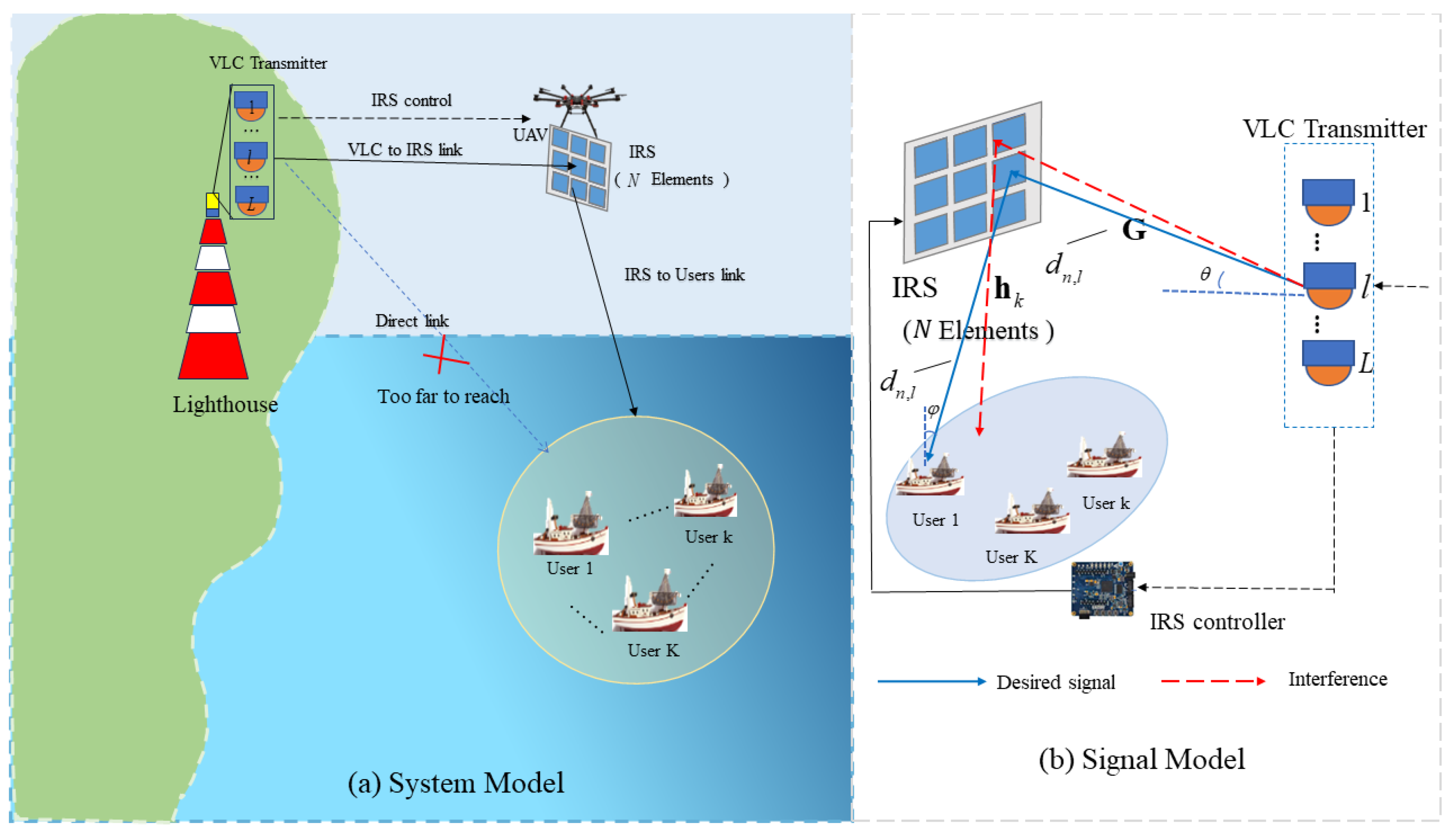
To enlarge the wireless communication coverage and improve the communication service ability with limited broadband in offshore areas, we propose an IRS-assisted VLC system, where an IRS mounted on a fixed located UAV is utilized to extend the onshore VLC base station service coverage.
(2)
In the proposed system model, we propose and solve the joint VLC transmit beamforming and the IRS phase shifting for maximizing the system’s energy efficiency. This joint optimization problem is solved by alternatively solving two subproblems, i.e., VLC transmit beamforming and IRS phase shifting. Accordingly, an alternative optimization-based energy efficiency maximization algorithm is proposed by closed-form optimal solutions obtained from two subproblems.
(3)
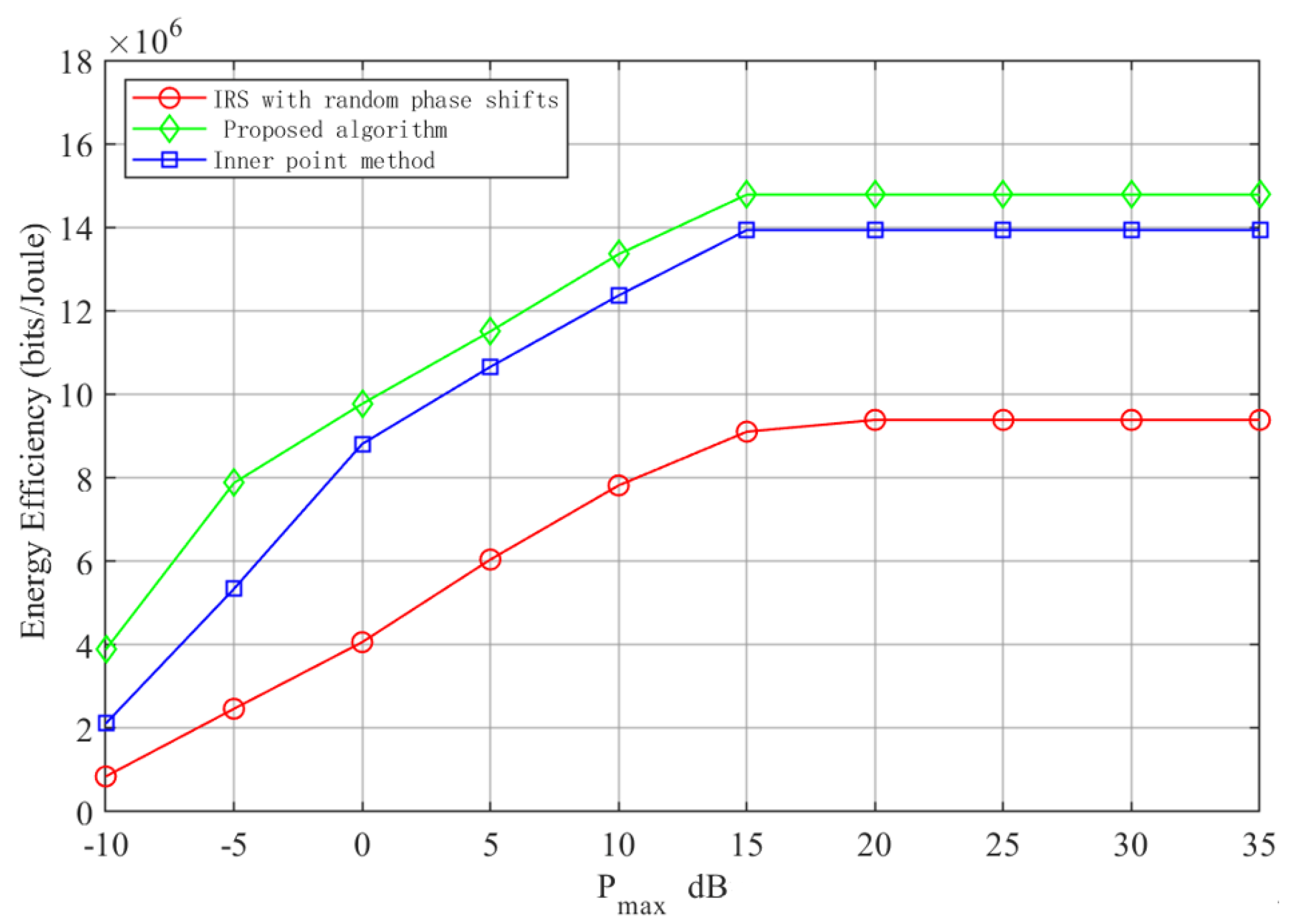
Numerical results demonstrate that the proposed joint optimization algorithm provides better performance compared with the benchmarks. Also, it is shown that the energy efficiency of the maritime communication system can be improved by applying the proposed joint optimization algorithm.

1.2. Paper Structure

The rest of the paper is organized as follows. Section 2 provides the details of the IRS-assisted VLC system model. The energy efficient optimization problem is also formulated. Section 3 presents an algorithm. Numerical results are presented and discuss in Section 4. Section 5 concludes the paper.
Notations: A H and A T denote the conjugate, conjugate transpose, and transpose of matrix A , respectively. x denotes the Euclidean norm of vector x . tr ( · ) denotes the trace of the matrix. Re · denotes the real part of its parameters. I denotes the unit matrix. R + denotes the set of positive real numbers. Table 1 shows the operation symbols and their definitions in this paper.

2. System Model and Problem Formulation

2.1. System Model

As shown in Figure 1, we consider a VLC-enabled UAV-IRS-assisted maritime communication system, where a VLC transmitter is deployed on the top of the lighthouse located onshore and attempts to transmit signals to K remote ship users. As the direct links between the onshore transmitter and ship users are unreachable, an IRS mounted on a rotary-wing UAV is adopted to assisted communication from the VLC transmitter to ship users. In this paper, we focus on optimizing the VLC-transmitted beamforming and IRS phase shifting for an energy-efficient IRS-assisted VLC transmission system; thus, we assume that the UAV is located in an arbitrary coordinate above the ship users. Here, the VLC transmitter is equipped with L LEDs for data transmission and L = 1 , , l , , L denotes the set of LEDs. The IRS is equipped with N reflecting elements and N = 1 , , n , , N denotes the set of IRS reflecting elements. The ship users set is denoted by K = 1 , , k , , K .
     For simplicity, we consider linear beamforming at an LED transmitter without loss of generality. Thus, suppose that the data symbol intended for the kth ship user can be expressed as
x k = k = 1 K ω k s k
where ω k C L × 1 is the corresponding beamforming vector, s k , k K is the zero-mean source information symbol, and E ( | s k | 2 ) = 1 .
We assume the link between the UAV to the IRS and the link between the IRS to the ship users are both LoS links, and the perfect channel state information (CSI) of all links is known by the VLC transmitter. Hence, according to  [18], the channel gain between the nth IRS to the kth ship user can be expressed as follows:
h n , k = δ A ( m + 1 ) 2 π ( d n , l ) 2 cos m ( θ ) g o f cos ( φ ) f ( φ )
where d n , k is the distance between the nth IRS to the k ship user. θ and φ are the angles of irradiance and incidence, respectively. δ is the reflectance of the IRS unit, A is the physical area of the user, m = ln 2 ln cos Δ 1 / 2 is the Lambertian emission with ln cos Δ 1 / 2 being the semi-angle at half-power of the transmitter, g o f is the optical filter gain, and f ( φ ) is the optical concentrator gain which results from the relationship between φ and the field of view (FOV).
Thus, for the kth ship user, the received data signal can be expressed as
y k = ρ k h k H Φ G j = 1 K ω j s j + n k
where h k = h 1 , k , h 2 , k , , h N , k C N × 1 denotes the channel vector between the IRS and the k ship user, and G C N × L denotes the received matrix between the VLC transmitter and the IRS. Φ = diag ( β 1 e j θ 1 , β 2 e j θ 2 , , β n e j θ n ) denotes the IRS phase shift matrix, which represents the diagonal matrix composed of N passive reflecting elements, while θ n [ 0 , 2 π ] and β n 0 , 1 denote the nth phase shift value and the reflection amplitude. In this paper, we focus on studying the impact of IRS phase shifting on system performance. Considering that each element experiences a similar communication environment, we assume that the IRS provides a maximum reflection amplitude and set β n = 1 , n N to omit the affect of reflection amplitude and focus on discussing shifting on system performance. ρ k denotes the user device responsively and n k is the additive Gaussian white noise (AWGN) obeying the distribution N ( 0 , σ k 2 ) , where σ k 2 is the variance value.
Accordingly, the signal to interference and noise ratio (SINR) of the kth ship user is given by
r k = ρ k ( h k H Φ G ) ω k 2 i = 1 , i k K ρ k ( h k H Φ G ) ω i 2 + σ k 2
The classical Shannon capacity formulation is not suitable for a VLC due to unique constraints such as non-negative amplitude and real-valued amplitude. Instead, a tight lower bound is proposed for a dimmable VLC in [20], so that the instantaneous rate achievable by the k ship user can be expressed as
R k = 1 2 B log 2 1 + e 2 π r k
where B R + is the modulation bandwidth, and e is the value of the natural logarithmic constant.
The total power consumed by the proposed system considered for operation consists of the LED transmission power and the hardware static power consumed in the LED, and the IRS controller power consumption. It is particularly important to emphasize that the IRS does not consume any transmit power because its reflector is a passive element that does not directly change the magnitude of the incoming signal. Any amplification gain provided by the IRS is obtained by properly adjusting the phase shift of the reflector element so that the reflected signal is phase-shifted coherent. Therefore, the total system power consumption can be expressed as
P total = k = 1 K w k 2 + P LED + P IRS
where P LED and P IRS are the hardware static power consumed by the LED device and IRS controller, respectively. The IRS power consumption depends on the type and resolution of the individual reflective elements, and for a smart surface with N identical reflective units, its power consumption is P IRS = N P n ( b ) , where P n ( b ) is the power consumption of each reflecting unit of the IRS having b-bit resolution.
Accordingly, the energy-efficiency (EE) performance of the proposed system can be obtained as the ratio of the achievable system sum rate (bps) to the total power consumption (joules), i.e.,
η EE = R total P total = k = 1 K R k k = 1 K w k 2 + P LED + N P n ( b )

2.2. Problem Formulation

Our goal is to maximize the EE of the proposed system by jointly optimizing the transmitted beamforming vector and the reflected beamforming vector. Mathematically, we can state the EE maximization problem as follows
P 1 : max Φ , w k , k K η EE
s . t . log 2 1 + e 2 π r k R k k K
k = 1 K w k 2 P max
θ n [ 0 , 2 π ] n N
where R k is the k th users’ minimum rate requirement and P max is the L LEDs’ total transmission power budget. Constraint (8b) guarantees the kth ship user’s minimum data rate requirement. Constraint (8c) denotes that the transmit power from LEDs cannot exceed their total power budget. Constraint (8d) guarantees the validity of the IRS phase shift value. It can be observed that the objective function is non-convex and the beamforming vector and IRS phase shifts are coupled in both objective function and rate requirement constraint. Thus, P1 is a non-convex optimization problem that is challenging to solve.

3. The Proposed EE Resource Allocation Scheme

In this section, we propose an EE resource allocation scheme to solve the formulated EE maximization problem. Due to the non-convexity of P 1 , to efficiently solve this problem, we decouple it into two subproblems, namely, VLC transmitter beamforming and IRS phase shifting. Then, an alternative optimization (AO)-based algorithm is proposed to obtain the suboptimal system EE. The details are given below.

3.1. Optimal VLC Transmitter Beamforming

For any given phase shifting matrix value Φ , P 1 can be rewritten as
P 2 : max w k k K η EE
s . t . log 2 1 + e 2 π r k R k k = 1 , 2 , . . . , k
k = 1 K w k 2 P max
It can be observed that P 2 is a non-convex optimal problem for the fractional objective function (9a). Since the fraction is difficult to solve, we apply the Dinkelbach method [21] to convert the objective function (9a) into a difference function. Thus, we introduce a variable λ = η EE and rewrite the objective function of P 2 as
R total λ k = 1 K w k 2 + P total
We define Z k = ρ k ( h k H Φ G ) ; then, (10) can be rewritten as
1 2 B k = 1 K log 2 1 + e 2 π Z k ω k 2 i = 1 , i k K Z k ω i 2 + σ k 2 λ k = 1 K ω k 2 + P total
We use the WMMSE method [24] to handle Equation (11). By introducing a linear decoding matrix U k , the kth user’s received signal y k is reconstructed as an evaluation signal vector s ^ k , which can be represented by s ^ k = U k H y k , where U k C 1 × 1 is the decoding matrix for the kth user.
E k = E ( s ^ k ) s k 2 = U k H Z k ω k I U k H Z k ω k I H + i = 1 k K U k H Z k ω i ω i H Z k H U k + σ k 2 U k H U k
where I is an identity matrix. Then, we transform the fractions in log 2
log 2 i = 1 , i k K Z k ω i 2 + σ k 2 + e 2 π Z k ω i 2 i = 1 , i k K Z k ω i 2 + σ k 2 = log 2 i = 1 , i k K Z k ω i 2 + σ k 2 + e 2 π Z k ω i 2 log 2 i = 1 , i k K Z k ω i 2 + σ k 2
Introduce the additional variable Q k C 1 × 1 , and apply it to the first term.
log 2 i = 1 , i k K Z k ω i 2 + σ k 2 + e 2 π Z k ω i 2 = log 2 Q k
The modulation bandwidth B is removable and is treated as a constant during optimization. In addition, a first-order Taylor expansion of log 2 Q k in the objective function is performed. Assuming that Q k is a small quantity, we have ln ( Q k ) ln ( Q o ) + Q k Q o Q o , where Q o is the value of Q k at some reference point. Choosing the reference point Q o = 1 because log 2 ( 1 ) = 0 simplifies the calculation, and bringing Q o = 1 into the Taylor expansion, the ln ( Q k ) Q k 1 .
Now, we compute tr ( Q k E k ) , where Q k is the extra variable for the kth user. Since Q k C 1 × 1 , it can be moved to the front of the matrix, yielding tr ( Q k E k ) = Q k tr ( E k ) .
Move the summation symbols in tr ( Q k E k ) to the outside of the objective function in (P2), and then convert it to multiplication using properties of logarithmic operations. Then, we have
k = 1 K ln ( Q k ) k = 1 K Q k tr ( E k ) log 2 i = 1 , i k K Z k ω i 2 + σ k 2 λ k = 1 K ω k 2 + P total
By introducing the additional variable Q k , the objective function of P 2 , in the form of (11), can be rewritten as
k = 1 K ln ( Q k ) tr ( Q k E K ) λ k = 1 K ω k 2 + P total
Then, we can rewrite P2 as following
P 2 : max Q k , U k , ω k , λ k = 1 K [ ln ( Q k ) tr ( Q k E k ) ] λ ( k = 1 K ω k 2 + P total )
ln ( Q k ) tr ( Q k E k ) R k
s . t . k = 1 K ω k 2 P max
For P2’, the optimal solutions of U k and Q k are obtained when the first-order derivatives of the objective function with respect to w are 0 , respectively, as
U k opt = J 1 h k H ω k
and
Q k opt = E k 1
where J = k = 1 K ( Z k ω k ) ( Z k ω k ) H + σ k 2 I .
Now that the auxiliary matrices U k and Q k have been optimized, we focus on optimizing the ω k , k K . Specifically, introducing Lagrange multipliers under the transmitter power budget constraint (17c) yields the following Lagrange function.
Γ = k = 1 K i = 1 K tr ( Q k U k H Z k ω i ω i H U k ) k = 1 K tr ( Q k U k H Z k ω j ) k = 1 K tr ( Q k ω l H Z k H ) + λ k = 1 K tr ( ω l ω l H + P total ) + μ k k = 1 K tr ( ω l ω l H P max )
where k , i , j , l K . The first-order derivative Γ ( ω k , λ , μ k ) obtains
ω l opt ( λ , μ k ) = Z k H U k Q k k = 1 K i = 1 K Z k H U k Q k U k H Z k + ( λ + μ k ) I
To obtain the complementary relaxation conditions for ω k following de-optimization, λ and μ k goes to satisfy the constraint (17c). According to
λ opt = M k = 1 K tr ( ω l ω l H ) + P total
where M = k = 1 K tr ( Q k U k Z k ) + k = 1 K tr ( Q k ω l H Z k H ) k = 1 K i = 1 K tr ( Q k U k k H Z ω i ω i H Z k H U k ) .
As the power limit is substituted into the Lagrangian equation, the last variable μ is introduced
k = 1 K tr [ ω l ( μ k ) ω l H ( μ k ) ] = P max
Thus, the closed form of the optimal μ k can be obtained according to [25].
μ k = l = 1 L Ξ M M S E P max
where · M M S E is the MMSE operation factor, and Ξ = k = 1 K T H ( Z k H U k Q k Q k H U k H Z k ) T , and we have T Λ T H = i = 1 K Z i H U k Q k U k H Z i

3.2. IRS Phase Shifting

In this subsection, we focus on optimizing the phase shift matrix Φ . By being given ω k , k K and matrix operations on P1, the phase shift optimization problem can be formulated as
P 3 : min Φ , θ n tr ( Φ A Φ B ) tr ( Φ C ) tr ( Φ C H )
s . t . tr ( Φ C H ) + tr ( Φ C 1 H ) tr ( Φ H A k Φ B ) R k
0 θ n 2 π n N
where A k = h k H U k Q k U k H h k , B = G j = 1 K ω k ω k H G H and C = h H ω k Q k U k H G ,   C = k = 1 K C k . (25b) is the minimum data rate requirement constraint transformed from (8b).
Using the matrix constancy equation of SDR, we have
tr ( Φ H A Φ B ) = ϕ H ( A B T ) ϕ
tr ( Φ C ) = c T ϕ
where c denotes the set of diagonal elements of C , and ϕ = β 1 e j θ 1 , , β n e j θ n , , β N e j θ N denotes the vector of diagonal element of Φ . Then, P 3 can be expressed as
P 3 : min ϕ , θ n ϕ H Ψ ϕ 2 Re { ϕ k H c }
s . t . 2 Re { ϕ H c } ϕ H Ψ ϕ R k
0 θ n 2 π n N
where Ψ = A B T is also a non-negative semidefinite matrix. The above equation is difficult to solve due to the non-convex constraint. Therefore, we apply the sequential fractional programming (SFP) optimization method to obtain approximate subproblems; then, we solve the problem by introducing a non-negative x. Using the Lagrangian pairwise decomposition method, we have
P 3 : max ϕ 2 Re { ϕ H t n } + 2 x Re { ϕ H ( c Ψ ϕ ( n ) ) }
s . t . 0 θ n 2 π n = 1 , 2 , . . . , N
For a given x, the optimal solution is ϕ ( x ) = e j ( t n + x ( c Ψ ϕ ( n ) ) ) , where t n = c + ( Λ max I N Ψ ) ϕ n is the maximum eigenvalue of Ψ . According to monotonicity, x should satisfy
x 2 Re { c Ψ ϕ ( n ) } R k = 0 .
Then, we have
Υ ( x ) = 2 Re ϕ ( x ) H c Ψ ϕ ( n )
Therefore, only by finding the correct x can the required phase shift be obtained. As shown in Algorithm 1, this process is repeated until the stopping criterion is satisfied. In each iteration, the value of x is adjusted to improve the objective function Υ ( x ) based on a comparison with a threshold value R k . The result can be obtained by Algorithm 1.
Algorithm 1 IRS Phase-Shifting Algorithm
Initialize:  x = 0 and set the iteration counter j = 0 .
Compute the maximum eigenvalue Λ max of Ψ
While the stopping criterion is not met:
   a. Solve P 3 using the current value of x to obtain the optimal solution ϕ ( x ) .
   b. Compute  Υ ( x ) = 2 Re { ϕ ( x ) H ( c Ψ ϕ ( n ) ) } .
   c. If  Υ ( x ) < R , increase x using a line search or other optimization method.
   d. Update the iteration counter: j = j + 1 .
Output the optimal solution ϕ ( x ) as the solution to the phase shift optimization problem.

3.3. EE Maximization Algorithm

In this subsection, an AO-based resource allocation scheme is proposed in Algorithm 2 according to the closed-form solutions obtained in Section 3.1 and Section 3.2. Algorithm 2 is an iterative optimization process where different variables are updated according to different subproblems in each iteration until certain convergence conditions are reached.
Algorithm 2 AO-based EE maximization algorithm.
Input:  K , P LED , P n ( b ) , P max , σ 2 , R k , h k , G and ε > 0
 Initialize:  Φ , ω k to feasible values
 While  | η E E ( l + 1 ) η E E ( l ) | 2 > ε , do
   Optimize with respect to ω k to obtain Φ
   Introduce variables λ , U k , Q k , μ k for iterative optimization
 repeat
    Update U k , Q k by (14)
    Update λ by (18), μ k by (19)
 until all the variables in the transmit beamforming matrix are obtained
 Optimize with respect to Φ to obtain ω k
 Update ω k with SFP method, SCA and Lagrange Pairing Method
 End while
  Output: Φ and ω k

4. Simulation Result

In this section, numerical results are provided to illustrate the performance of the 315 proposed algorithms. The coordinates of IRS and LEDs are (8, 0, 4) m and (−12, 4, 8) m, respectively. Assume that users are randomly and uniformly placed in an IRS-centered circle with a radius of 6 m. According to the white LED light channel modeled in [26] and its communication performance and corresponding parameters discussed in maritime communication [27], we set the noise with a power density of −86 dBm/Hz. The simulation parameters are given in Table 2.
The average convergence performance of the algorithm, which is the convergence of the iterative WMMSE method, is given in Figure 2 below. The results show that the algorithms have a fast convergence rate. It also can be observed that with a lower power budget, the optimal value can be obtained with a faster convergence speed. That is because the available power for signal transmission is limited. This limitation makes it easier for the system to find the optimal solution that meets the constraints. The constraints of the problem become tighter, reducing the search space, and leading to smaller changes in the power adjustment with each iteration.
A comparison of the iterative convergence process of various noise power algorithms is presented in Figure 3 below. The different initializations, denoted as 1, 2, and 3, correspond to the noise power levels of σ 2 = 76 dBm, 86 dBm, and 96 dBm, respectively. The results demonstrate that the algorithm converges rapidly, typically requiring only four to six iterations to reach convergence. Based on these findings, the proposed algorithm is deemed to be an effective solution for the problem at hand.
Figure 4 shows the system energy efficiency constrained by different transmit power budgets under different phase-shifting algorithms. We introduce IRS-assisted VLC under IRS random phase shift using the interior point method as benchmarks. In Figure 4, we can observe that at the beginning of the curve, the energy-efficiency value increases gradually with the increase of P max . As P max becomes larger and sufficiently large, the energy efficiency gradually converges to a constant value. In other words, it first increases monotonically with the maximum transmitting power and then reaches a maximum value. After meet the maximum value, the system’s energy efficiency can only offer a slight increase with the transmit power increasing. This observation provides a theoretical basis for selecting an appropriate maximum total power.
Furthermore, it is evident from Figure 3 that the proposed scheme performs better than the other two methods. The maximum value of energy efficiency can reach 14.2, which is significantly better than the typical interior point method and IRS with random phase.
Figure 5 illustrates the system energy efficiency performance versus the different numbers of IRS-reflecting elements.It is shown in Figure 5 that the system energy efficiency improves as the increasing number of IRS-reflecting elements. This improvement is primarily attributed to the fact that using more elements enhances the signal and achieves better communication performance for the users.
Furthermore, the algorithm is also analyzed and compared with a random phase IRS approach, considering different numbers of LED transmitters. It is evident that the energy efficiency of both schemes, the proposed scheme and the scheme with random phase IRS, increases with the increase in the number of reflective elements. With the same number of LED transmitters, the proposed scheme in this paper consistently exhibits higher energy efficiency than the random phase scheme.
However, it is worth noting that the improvement eventually becomes less pronounced as the number of reflecting elements (L) increases. This is primarily because a fixed P max , when increasing L, narrows the feasible domain of each LED channel, leading to diminishing returns in terms of energy-efficiency improvement.

5. Conclusions

In this paper, we studied an energy-efficient resource allocation scheme in an IRS-assisted VLC system for offshore maritime communication. The formulated EE maximization problem has been solved by jointly optimizing the transmission beamforming and IRS phase shifting. Due to the non-convexity of the proposed problem, the Dinkelbach method and mean-square error (MSE) method are adopted to turn the non-convex origin problem into two equivalent problems, namely transmit beamforming and reflected phase shifting. The Lagrangian method and SDR technique are used to obtain the closed-form solutions of these two subproblems. Accordingly, an AO-based resource allocation algorithm is proposed to obtain optimal system EE. The simulation results demonstrate that the proposed algorithm can obtain a better system EE performance over benchmark schemes.

Author Contributions

Conceptualization, W.X.; methodology, W.X.; software, L.G.; validation, W.X. and L.G.; formal analysis, W.X. and L.G.; investigation, W.X.; resources, W.X.; data curation, L.G.; writing—original draft preparation, W.X. and L.G.; writing—review and editing, W.X.; supervision, W.X.; project administration, W.X.; funding acquisition, W.X. All authors have read and agreed to the published version of the manuscript.

Funding

This research was funded by the Shanghai Sailing Program, grant number 20YF1416700, Innovation Program of Shanghai Municipal Education Commission of China under Grant 2021-01-07-00-10-E00121, the National Natural Science Foundation of China (62271303).

Institutional Review Board Statement

Not applicable.

Informed Consent Statement

Not applicable.

Data Availability Statement

Data are contained within the article.

Acknowledgments

The authors are grateful to the anonymous reviewers for their constructive comments that have improved the presentation of this paper significantly.

Conflicts of Interest

The authors declare no conflicts of interest.

References

  1. Li, X.; Feng, W.; Chen, Y.; Wang, C.X.; Ge, N. Maritime coverage enhancement using UAVs coordinated with hybrid satellite-terrestrial networks. IEEE Trans. Commun. 2020, 68, 2355–2369. [Google Scholar] [CrossRef]
  2. Yang, H.; Lin, K.; Xiao, L.; Zhao, Y.; Xiong, Z.; Han, Z. Energy harvesting UAV-RIS-assisted maritime communications based on deep reinforcement learning against jamming. IEEE Trans. Commun. 2024; Early Access. [Google Scholar] [CrossRef]
  3. Zhou, Z.; Ge, N.; Liu, W.; Wang, Z. RIS-aided offshore communications with adaptive beamforming and service time allocation. In Proceedings of the ICC 2020—2020 IEEE International Conference on Communications (ICC), Dublin, Ireland, 7–11 June 2020; p. 1C6. [Google Scholar]
  4. Yang, Y.; Zeng, Z.; Cheng, J.; Guo, C.; Feng, C. A relay-assisted OFDM system for VLC uplink transmission. IEEE Trans. Commun. 2019, 67, 6268–6281. [Google Scholar] [CrossRef]
  5. Wong, V.W.; Schober, R.; Ng, D.W.K.; Wang, L.-C. Key Technologies for 5G Wireless Systems; Cambridge University Press: Cambridge, UK, 2017. [Google Scholar]
  6. Abumarshoud, H.; Selim, B.; Tatipamula, M.; Haas, H. Intelligent Reflecting Surfaces for Enhanced NOMA-based Visible Light Communications. In Proceedings of the ICC 2022—IEEE International Conference on Communications, Seoul, Republic of Korea, 16–20 May 2022. [Google Scholar]
  7. Obeed, M.; Salhab, A.M.; Alouini, M.-S.; Zummo, S.A. On optimizing VLC networks for downlink multi-user transmission: A survey. IEEE Commun. Surv. Tutor. 2019, 21, 2947–2976. [Google Scholar] [CrossRef]
  8. Qian, L.; Chi, X.; Zhao, L.; Chaaban, A. Secure visible light communications via intelligent reflecting surfaces. arXiv 2021, arXiv:2101.12390. [Google Scholar]
  9. Tan, X.; Sun, Z.; Koutsonikolas, D.; Jornet, J.M. Enabling indoor mobile millimeter-wave networks based on smart reflect-arrays. In Proceedings of the IEEE INFOCOM 2018—IEEE Conference on Computer Communications, Honolulu, HI, USA, 16–19 April 2018; pp. 1–9. [Google Scholar]
  10. Saifaldeen, D.A.; Ciftler, B.S.; Abdallah, M.M.; Qaraqe, K.A. DRL-Based IRS-assisted secure visible light communications. IEEE Photonics J. 2022, 14, 1–9. [Google Scholar] [CrossRef]
  11. Rabiepoor, A.; Nezamalhosseini, S.A.; Chen, L.R. IRS-assisted vehicular visible light communications systems: Channel modeling and performance analysis. Appl. Opt. 2024, 63, 167–178. [Google Scholar] [CrossRef] [PubMed]
  12. Cao, X.; Hu, X.; Peng, M. Joint mode selection and beamforming for IRS-aided maritime cooperative communication systems. IEEE Trans. Green Commun. Netw. 2023, 7, 57–69. [Google Scholar] [CrossRef]
  13. Li, K.; Cui, M.; Zhang, G.; Wu, Q.; Li, D.; He, J. Robust transmit and reflect beamforming design for IRS-assisted Offshore NOMA communication systems. IEEE Trans. Veh. Technol. 2024, 73, 783–798. [Google Scholar] [CrossRef]
  14. Zhao, L.; Wang, Z.; Wang, X. Wireless power transfer empowered by reconfigurable intelligent surfaces. IEEE Syst. J. 2020, 15, 2121–2124. [Google Scholar] [CrossRef]
  15. Huang, C.; Zappone, A.; Alexandropoulos, G.C.; Debbah, M.; Yuen, C. Reconfigurable intelligent surfaces for energy efficiency in wireless communication. IEEE Trans. Wirel. Commun. 2019, 18, 4157–4170. [Google Scholar] [CrossRef]
  16. Chen, C.; Fu, S.; Jian, X.; Liu, M.; Deng, X. Energy-efficient NOMA with QoS-guaranteed power allocation for multi-user VLC. In Proceedings of the 2021 IEEE 16th Conference on Industrial Electronics and Applications (ICIEA), Chengdu, China, 1–4 August 2021. [Google Scholar]
  17. Hu, S.; Wu, Q.; Wang, X. Energy management and trajectory optimization for UAV-enabled legitimate monitoring systems. IEEE Trans. Wirel. Commun. 2021, 20, 142–155. [Google Scholar] [CrossRef]
  18. Cang, Y.; Chen, M.; Zhao, J.; Yang, Z.; Hu, Y.; Huang, C.; Wong, K.K. Energy Joint deployment and resourve management for VLC-enabled RISs-assissted UAV networks. IEEE Trans. Wirel. Commun. 2023, 22, 746–760. [Google Scholar] [CrossRef]
  19. Yang, Z.; Chen, M.; Saad, W.; Xu, W.; Shikh-Bahaei, M.; Poor, H.V.; Cui, S. Energy-efficient wireless communications with distributed reconfigurable intelligent surfaces. IEEE Trans. Wirel. Commun. 2021, 21, 665–679. [Google Scholar] [CrossRef]
  20. Sun, S.; Yang, F.; Song, J. Sum Rate Maximization for Intelligent Reflecting Surface-Aided Visible Light Communications. IEEE Commun. Lett. 2021, 25, 3619–3623. [Google Scholar] [CrossRef]
  21. Tang, J.; Peng, Z.; Zhou, Z.; So, D.K.C.; Zhang, X.; Wong, K.-K. Energy-Efficient Resource Allocation for IRS-aided MISO System with SWIPT. In Proceedings of the GLOBECOM 2022—2022 IEEE Global Communications Conference, Rio de Janeiro, Brazil, 4–8 December 2022. [Google Scholar]
  22. Najafi, M.; Schmauss, B.; Schober, R. Intelligent reflecting surfaces for free space optical communication systems. IEEE Trans. Commun. 2021, 69, 6134–6151. [Google Scholar] [CrossRef]
  23. Sun, S.; Yang, F.; Song, J.; Han, Z. Joint Resource Management for Intelligent Reflecting Surface–Aided Visible Light Communications. IEEE Trans. Wirel. Commun. 2022, 21, 6508–6522. [Google Scholar] [CrossRef]
  24. Pan, J.; Ma, W.-K.; Xia, X.; Tian, Y. WMMSE-based multiuser MIMO beamforming: A practice-oriented design and LTE system performance evaluation. In Proceedings of the 2015 IEEE 16th International Workshop on Signal Processing Advances in Wireless Communications (SPAWC), Stockholm, Sweden, 28 June–1 July 2015; pp. 435–439. [Google Scholar]
  25. Lu, R. Energy-efficiency optimization in dual reconfigureable intelligent surfaces wireless communication system. In Proceedings of the 2021 6th International Symposium on Computer and Information Processing Technology (ISCIPT), Changsha, China, 11–13 June 2021; pp. 470–473. [Google Scholar]
  26. Liu, X.; Na, Z.; Wang, Y.; Durrani, T.S. Joint Resource Allocation for a Novel OFDM-Based Multicolor VLC Network. IEEE Netw. Lett. 2021, 3, 100–104. [Google Scholar] [CrossRef]
  27. Zheng, X.T.; Guo, L.X.; Cheng, M.J.; Li, J.T. Average BER of Maritime Visible Light Communication System in Atmospheric Turbulent Channel. In Proceedings of the 2018 Cross Strait Quad-Regional Radio Science and Wireless Technology Conference (CSQRWC), Xuzhou, China, 21–24 July 2018; pp. 1–3. [Google Scholar]
Figure 1. System and signal model. (a) shows the VLC-enabled UAV-IRS-assisted maritime communication system model. (b) shows the signal model that signal is transmitted from VLC transmitter to user ships assisted by IRS.
Jmse 12 00772 g001
Figure 2. Convergence performance of the proposed Algorithm 2 under an LED power budget.
Jmse 12 00772 g002
Figure 3. Convergence of the proposed algorithm under different initialization cases.
Jmse 12 00772 g003
Figure 4. System energy efficiency versus LEDs transmit power budget under different phase-shifting algorithms.
Jmse 12 00772 g004
Figure 5. Energy efficiency versus number of reflecting elements.
Jmse 12 00772 g005
Table 1. Symbols and Descriptions.
SymbolDescription
A H Conjugate transpose of matrix A
A T Transpose of matrix A
x Euclidean norm of vector x
tr ( · ) Trace of the matrix
Re ( · ) Real part of its parameters
A Conjugate of matrix A
I Unit matrix
R + Set of positive real numbers
Table 2. System parameters.
ParameterValueParameterValue
Bandwidth B20 MHz δ 0.5
LED hardware static power P LED 2 mwatt g of 1
The area of an IRS unit10 × 10 cm2m1
The number of LEDs6A 4 cm 2
The number of IRS units16 φ 80
Total emission power constraint, P max 20 watt P n ( b ) 0.5 mwatt
LED location coordinates ( 8 , 0 , 4 ) m
IRS location coordinates ( 12 , 4 , 8 ) m
Minimum data rate requirement, R min 0.5 bps/Hz
Disclaimer/Publisher’s Note: The statements, opinions and data contained in all publications are solely those of the individual author(s) and contributor(s) and not of MDPI and/or the editor(s). MDPI and/or the editor(s) disclaim responsibility for any injury to people or property resulting from any ideas, methods, instructions or products referred to in the content.

