Abstract
The intensive integration of technology and the demand for high-level performance are specific features of warships, which are at present one of the most complex systems. An appropriate design process, able to foresee in a life cycle perspective, is necessary to properly implement the emergent properties and the capabilities required for the warship in the different operational profiles. This paper will delve into the integration of the Systems Engineering (SE) approach into the realm of naval ship design, fostering an innovative perspective. An integration of the design spiral method with the SE approach will be described, making possible the definition of a hinge between the two realms and depicting a novel comprehensive approach where the ship platform and the so-called payload are finally interconnected with each other.
1. Introduction: The Complexity of Warship Design
The design process of a warship often requires a superior effort and resources when compared to merchant vessels: more and diverse stakeholders are involved and the ship’s technical specifications are identified starting from mission and capabilities requirements with a dedicated process. Platform systems such as the energy system and its distribution grid, sensors, weapons, and communication systems need to work as a whole, under the control and management of personnel onboard.
This array of systems reflects the multiplicity of a warship’s functions, as opposed to the single/few functionality/ies (typically goods transportation) of many merchant vessels. For example, a commercial ship needs a radar system only for navigation; a warship, on the other hand, requires such a system not only for navigation but also for detecting threats and engaging them.
The idea of the naval ship as a complex system is recognized by many authors, for example, D. Andrews, who defines the warship as a physically large and complex (PL&C) system [1]. In this perspective, he stated that ship design is a “wicked problem”, i.e., the problem is not understood until the formulation of a solution and for that reason determining the actual requirements is really challenging. Moreover, for complex systems, it is not possible to directly identify a unique possible solution to the problem. The characteristics of a “complex system” are defined by M. Clemens of the New England Complex Systems Institute [2] as a gathering and integration of diverse entities, each with specific attributes and fundamental behaviors, but more importantly, they interact with each other and with the surrounding environment and contextual factors. In naval vessels, platform and combat systems act as a whole in the operational environment, to meet mission requirements established by stakeholders. As a result of successful integration, the entire ship system exhibits qualities that do not exist in any of its individual components, giving rise to emergent properties at various scales.
The idea of the ship as a complex system was also the basis of the project HOLOSHIP [3], where a systemic approach was defined to describe the ship as the sum of various subsystems and components. This approach deals with the complexity of a surface unit by employing a holistic vision. The project specifically refers to cargo ships, describing subsystems such as cargo storage, energy/power generation, propulsion, crew/passenger accommodation, and navigation. Furthermore, the HOLOSHIP project highlights certain limitations of the Design Spiral and emphasizes the need to transition towards a more modern and comprehensive life cycle perspective.
Modern ship design approaches also embrace a systemic perspective by treating the ship as an assembly of modular components. These modules can be replaced throughout the ship’s life cycle to adapt to different transport and operational scenarios. This approach, known as “Modular-based Ship Design” or “Set-based Ship Design” [4,5] allows for flexibility and facilitates retrofitting to enhance transport services in terms of efficiency and safety. This modular methodology has found broader application in naval and multi-purpose ship design, and it could potentially be an ambitious feature to be integrated into the authors’ proposed theoretical approach in future developments.
The integration of the design spiral in the framework of the se approach, described in the paper, is meant to provide a systemic vision to put the theoretical foundation to deal with the described problem and lead the whole system toward a specific solution. As highlighted in the following sections, an update to the overall method of designing naval ships must include the identification and definition of specific metrics. Therefore, future advancements in the proposed approach will involve the incorporation of innovative computational tools, such as CAD [6], PLM [7] and operational simulations [8], which will provide reliable prediction of ship performance, particularly within a life cycle perspective.
2. The Design Spiral: Points of Strength and Weakness
Traditionally the design of a ship is performed by making use of the well-known “Design Spiral”, which was originally introduced by J. H. Evans in 1959 [9]. Evans intended to develop a rational comprehensive design procedure for a surface cargo ship, enabling the trade-off process and the convergence toward solution efficiently and possibly taking advantage of automatic tools.
A design spiral specifically elaborated for naval ship design was published by Watson in 1998 [10] and it is shown in the right part of Figure 1.
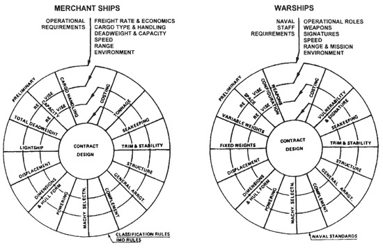
Figure 1.
The Design Spiral for merchant ships and warships by Watson [10].
The spiral illustrates how several ship properties are assessed with proper sequencing in a linear iterative process, on the basis of previous steps, which in turn are established with assumptions on the following ones, still unknown. Figure 1 displays two tailored design spirals, for merchant vessels and warships, showcasing their similarities and differences, in particular for what concerns the input requirements for the procedure. However, the resemblances are more prevalent.
Over the decades, several attempts have been made to improve the original spiral in terms of model representation and inclusion of aspects not considered previously. The efforts to modernize the original design spiral model and the evolution of the design techniques emphasized that the spiral approach cannot well represent the entire life-cycle process of the ship, requiring a wider vision.
One of the most discussed weak points of the design spiral is the lack of a proper approach to define the ship requirements and well explore the problem domain before formulating trade-off analysis of possible solutions. This is because the traditional design spiral starts its process when requirements have been already defined in agreement with the client and use them as input to develop a balanced solution.
Thus, some researchers started to find a way to integrate the elucidation of requirements into the ship design spiral process, for example, Levander [11] and Papanikolaou [12] tried to merge the ship requirements definition in the spiral process.
The flaws of the design spiral are described by Andrews who dedicated a lot of his work [13,14,15] to analyzing warship design methodologies and in particular the validity of the design spiral approach. He identifies two aspects of ship design, iterative and interactive, stating that only the iterative aspect is well captured by the Design Spiral, and even then, only in the specific steps represented.
As Papanikolaou, Andrews underlines how Early Stage Ship Design (ESSD) is a peculiar process, which must be treated with a different approach than the design spiral [16]. Indeed, its purpose is the exploration of different possible architectures to identify the requirements needed to properly make use of the design spiral, rather than the design of the vessel itself.
Many other authors found flaws in the design spiral method and felt the necessity to discuss a novel approach. Brown for example stated [17] that the concept design phase is a delicate process, which is not well represented by the design spiral. In his opinion, naval ship concept design relies heavily on an ad hoc approach, where design concepts are chosen based on experience, design lanes, rules of thumb, personal preferences, and imagination.
Bruinessen et al. point out some limits of the design spiral [18], stating that the model effectively represents the progressive refinement of design details, but it lacks flexibility in adapting to evolving system choices, solutions, or requirements. The main flaws attributed to the design spiral traditional approach can therefore be resumed as follows:
- Close process: the interactions with all the stakeholders involved in the design process are not rationally described in the Design Spiral stages and it is not clear when and how their feedback is needed to assess the solution.
- Inappropriate Early Stage Ship Design: the decisional process in the early phases of the ship design is crucial to well define the problem and identify the requirements needed. The requirements identification is taken for granted and it is completely left out of the design process, which uses them as input.
- Lack of a Life-Cycle vision: it considers only the design stage of the ship’s entire life, excluding from the design process the influences of significant phases like overarching architectures, operational life, maintenance, and retirement.
- Linear approach: the naval architectural aspects of the design cannot be adequately structured and represented by flow diagrams like the design spiral. This is due to the process involving closed loops and intuitive leaps, while performance functions are nonlinear and often discontinuous. In addition, inequalities are more common than equations in this context. The looping, nonlinear, and discontinuous nature of the design process creates challenges not only for representing it using the design spiral but also for computer-based systems widely used for achieving balanced solutions through rapid iterations [19].
The Design Spiral seems to work well in a further phase of the design process once the requirements have been defined and they need to be put together in a final balance solution. The definition of requirements in the early design stages is often executed using the ‘experts’ perspective and rule of thumb, constraining the design by previously known and workable technical solutions.
Moreover, the time-consuming efforts for the several iterations necessary to achieve the final result usually favor the adoption of a past and already consolidated reference model, limiting the project merely to a tuning and customization process that can certainly meet the operational requirements, but which is not necessarily the best possible solution. Thus, the spiral process addresses mainly the engineering of the vessel once the main requirements and functions have been made.
From all the above discussions it derives how the design spiral method needs to evolve to keep pace with modern systems and industry needs. The lack of a mode in the design spiral process to assess the solution’s effectiveness demands a quantitative methodology to assist the designers and the customers in the decisional process, which is the foundation to identify and design the needed ship solution. Thus, to upgrade the traditional warship design methodology and apply a whole system vision, the Systems Engineering (SE) approach is a sound resource, that applies the systems approach to observe large and complex systems design exploration, development, and problem-solving through systematic and systematic processes.
3. Overview of Systems Engineering Approach
In this section, a brief introduction to SE main features will be given, keeping in mind the level of complexity of a naval ship and the point of weakness (and strength) put in evidence for the linear iterative model of the ship design process represented by means of the design spiral.
Systems engineering is commonly recognized as a powerful approach to enable the realization of complex systems also in a life-cycle perspective. Considering in particular the design phase, it aims to focus on effectively defining stakeholder’s needs and requirements in the early design process, translating them into a technically feasible solution. It encompasses a wide range of activities to ensure that the final product fulfills its intended purpose, both from a technical and economic point of view. It is based on activities such as trade-off analysis and optimization procedures, aimed to provide successful integration among different technical engineering knowledge and systems [20].
One of the most important features of SE is that it enables the grasp and modeling of a complex system as a whole besides the visualization of the different parts in interaction and it permits the implementation of socio-technical aspects into the process [21]. From what above, Systems Engineering can be briefly defined as a systemic and systematic approach with the aim of identifying the best possible solution that fulfills the stakeholder’s needs and translates them into technical requirements [22]. It is a systematic approach because it refers to taking a structured, orderly methodology to solve the problem and to implement the system; it can also be defined as a systemic approach because it refers to the holistic appreciation of the system of interest, considering its context, stakeholders, and the interrelationships and interconnections.
In past years, several models have been developed to graphically represent the SE processes throughout the main life stages of a system. These can be classified into three major categories: iteration and recursion methods, sequential methods, and incremental and iterative methods [20].
There a “perfect model” does not exist among the three presented above, but it depends on the organization that will produce the system and on the nature of the system to be designed. However, the most widespread model used to represent SE approach is the V-model. Several representations of the V-model can be found in the literature, but one of the most comprehensive in the transportation field has been developed by the Federal Highway Administration of the U.S. Department of Transportation [23].
Figure 2 represents a model developed by the authors and adapted from the previously mentioned one [23] to better depict the warship’s main design steps. The model illustrates SE activities throughout the life cycle stages, with time and system maturity progressing from left to right. The blue color of the processes intensifies as it descends along the legs, representing an increasing level of detail. The “wings” have been added recently to the modern V-models to include the entire project life cycle.
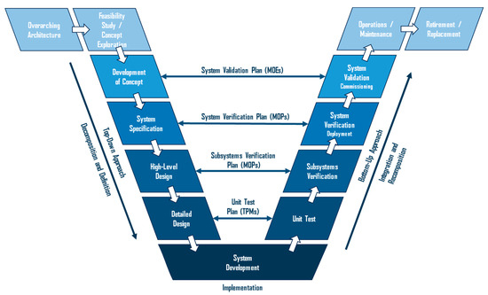
Figure 2.
The Systems Engineering V-Model.
This model represents how SE is the fusion of two different design approaches: the top-down and the bottom-up processes. On the left leg, there is the top-down process (Decomposition and Definition), where the system definition evolves from an initial high-level user perspective to a detailed specification of the system design. The System of Interest (SOI) is broken down into subsystems and further into components, allowing for a hierarchical organization of large systems, which are divided into smaller pieces through multiple layers of decomposition. Simultaneously, the requirements are also broken down into more specific ones, which are then allocated to the corresponding system components. The top-down process guarantees that the starting requirements are met but cannot ensure the physical feasibility of the product.
The practical realization of the asset takes place at the bottom of the “V” model, while on the right leg the bottom-up process takes place (integration and recomposition), where integration and verification of the components and system take place. Ultimately, the completed system is subjected to validation to assess how effectively it meets the user’s needs. The right leg bottom-up process guarantees that the product is physically feasible and jointly with the top-down process on the left leg ensures that the final product fulfills the starting requirements.
The V-model certainly reduces project risks by:
- Improving the quality of the design.
- Controlling costs throughout the entire life cycle framework.
- Enhancing interaction among stakeholders.
However, it does not inherently address time management in the planning and realization of the project.
The key to the V-model is the V representation itself. The two legs are not sequential to each other, but they coexist from the very beginning representing the strength of the SE. Indeed, the top-down and bottom-up processes are kept together by the core of the model, which metaphorically also represents the core of the entire SE methodology. The symmetric structure of the V-model highlights the interrelation between the left and right sides of the model, demonstrating the correlation between the activities performed on the left side and their corresponding verifications on the right side. The system definition established on the left serves as the basis for validating the system on the right.
Thus, at each level, there exists a deliberate and direct correspondence between the activities on the left and right sides. This approach ensures that the verification method is determined and defined as the requirements are developed and documented at each level. Even at the initial and highest level, when user requirements are translated into system requirements, the system verification approach must be established to ensure that the system fulfills its intended purpose. The verification process can significantly impact cost and schedule and may serve as a differentiating factor between alternative concepts.
Verification and Validation are then the core of the V-model and it is important to note the clear distinction between verification and validation. Verification focuses on proving that each product meets its specified requirements (answering the question: “Have we built the system right?”). On the other hand, validation aims to demonstrate that the product satisfies the user’s needs, irrespective of what the system specification demands (answering the question: “Have we built the right system?”).
Metrics are a crucial part of the Systems Engineering processes, allowing quantitative and objective measures to evaluate the goodness of the system under analysis. The purpose of metrics is to gauge progress toward a goal or continuous product improvement. Achieving a goal or improvement requires action, which should be based on the data collected from the metrics and their interpretation. Below are described different categories of technical measures commonly used to obtain detailed information on solution performance during development. It is crucial to recognize that within KPIs (Key Performance Parameters), a hierarchical order is necessary to manage the process systematically and systemically, especially for complex systems with numerous parameters at play. The definitions provided are derived from INCOSE [20,24], which shows that technical measures can be divided into the following four groups:
- Measures of Effectiveness (MOEs)“The “operational” measures of success that are closely related to the achievement of the mission or operational objective being evaluated, in the intended operational environment under a specified set of conditions; i.e., how well the solution achieves the intended purpose.” INCOSE
- Measures of Performance (MOPs)“The measures that characterize physical or functional attributes relating to the system operation, measured or estimated under specified testing and/or operational environment conditions.” INCOSE
- Technical Performance Measures (TPMs)“TPMs measure attributes of a system element to determine how well a system or system element is satisfying or expected to satisfy a technical requirement or goal.” INCOSE
- Key Performance Parameters (KPPs)“A critical subset of the performance parameters representing those capabilities and characteristics so significant that failure to meet the threshold value of performance can cause for the concept or system selected to be reevaluated or the project to be reassessed or terminated.” INCOSE
The distinction between ‘effectiveness’ and ‘performance’ highlights that Measures of Effectiveness (MOEs) and Measures of Performance (MOPs) are formulated from distinct perspectives. An MOE relates to the effectiveness of a solution and is not tied to any specific solution; in contrast, an MOP pertains to the actual performance of a chosen entity or solution. The MOE reflects the intentions of stakeholders, whereas the MOP focuses on the tangible performance of the supplier’s solution, which may deviate from stakeholders’ intentions. Moreover, a MOE identifies a property that a potential solution must possess to fulfill a need, while a MOP reveals the capabilities of something, even if it’s not necessarily what stakeholders desire it to do.
It is possible to see where the described measures have a crucial role in the “V” model processes. At the highest level, MOEs come into play and are essential for the Validation Process, by centering on meeting acquirer needs. They serve to quantify value, aiding in the justification of procurement decisions and, at the project’s conclusion, in quantifying system validation.
Developers utilize KPPs to define the essential requirements needed to attain the MOEs. KPPs, in turn, guide the establishment of MOPs, which are assessed as early as possible and repeatedly throughout the development, testing, and evaluation phases. MOPs play an essential role in the verification process, verifying that the system adheres to the system’s technical requirements, and facilitating the validation of these requirements to align with mission objectives and acquirer needs.
TPMs offer a more detailed breakdown of MOPs, often driven by identified risks, with the goal of providing measurable and continuous insights into technical progress. These measures are assessed through various means, including analysis, modeling, simulation, and appropriate verification methods such as testing. As development progresses, periodic estimations of MOEs are derived using MOP and TPM values to ensure the likelihood of meeting MOEs.
It seems clear how SE is a powerful tool to manage the design of complex systems, such as naval ships, being able potentially to overcome the traditional design spiral flaws, described in Section 2, and supply warship design with a wider and modern vision. Many international figures tried in the past years to apply SE concepts to naval ship design: Andrews [25] developed a new methodology to face the peculiarity of early stage design, which makes use of SE approach. Decomposition is largely used to approach the complexity of warship design, by Gaspar et al. [26], to separate the whole system into separated basic elements and subsystems, making it more comprehensible. Brown [27,28] also makes use of capability-based approaches to decompose the ship’s complex system and he largely makes use of SE metrics. The necessity to use metrics to evaluate the adequacy of the solution under design has been also underlined in the already mentioned project HOLISHIP [3], where “measures of merit” have been defined to properly instruct the design optimization procedures.
However, there is still the necessity for a commonly recognized methodology that exploits the strength of both the design spiral and the systems engineering approach, encouraging the designer, right from the initial design stage, to prioritize the functions of a naval ship rather than the individual components that constitute it. This shift in perspective is demanded to grasp “what” is necessary to meet the customer’s requirements before delving into the technical aspects of “how” to achieve those objectives.
The forthcoming chapter will delve into the integration of the Systems Engineering (SE) approach into the realm of naval ship design, fostering an innovative perspective.
4. A Proposal for the Integration of the V-Model and the Design Spiral
As stated in the previous sections, the design spiral and the V-Model merging is assumed to be an interesting activity to empower naval ship design. In this perspective, it is necessary to define how the two methodologies could interact with each other and when during the design process [29].
Figure 3 points out an aspect that is not often represented: indeed, the V-Model is usually depicted in a 2-D mode, implying that processes evolve only from the left to the right (see Figure 2 in the previous section). However, this is only an interpretation of the original model, initially developed by Forsberg [30] in 1991 and intended as a 3-D model. The 3D representation implies that, at each step of the V-Model, parallel activities are going on at the same time. It also represents the level of detail, which increases while descending the model, where the attention goes from the general system to its components.
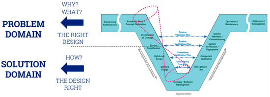
Figure 3.
The different domains of the V-Model.
To better discuss the processes the following actions are needed:
- -
- Definition of technical features starting from needs (problem domain)
- -
- Subsequent development of details for the system identified as a solution (solution domain)
A double cone figure, possibly resembling an hourglass, can be used on the left leg of the V-Model, as the one shown in red in Figure 3. The upper cone (Problem Domain) identified as P-Cone depicts the stage where a problem is identified and understood, concentrating on understanding the needs in order to formulate requirements, answering the questions “what is the right asset I need and why?” [31]. For instance, this involves gathering information, defining goals and objectives, and exploring the factors contributing to the problem with the aim of being ready for product functionalities identification.
The large base of the P-Cone implies that the discussion about requirements identification is very open. Convergence in the process is provided by solving possible conflicts among requirements and by selecting the most significant requirements in terms of priority. At the end of the problem domain, represented by the upper cone’s apex, the technical specifications of the solution to fulfill the stakeholder’s needs, have been selected. During the P-Cone processes, computational tools, such as operational simulations, can be applied to support the designers’ decisional process.
The lower cone (solution domain) identified as S-Cone pertains to the space where potential solutions are assessed in terms of compliance with the issues identified in the problem domain. In this phase, the question is: “how do we build the identified right design?” [31]. The focus shifts therefore from understanding the problem to crafting the solution. In S-Cone the increasing diameter is meant to represent the increasing level of knowledge about details. Indeed, the solution implementation starts from the general system, which is represented by the S-Cone’s apex, and proceeds to define the subsystems and components in the lower processes of the left leg.
The development along the design spiral of the ship design steps (from feasibility study to detailed design) [32] perfectly fits with the lower part of the left leg and the S-Cone (see Figure 4): once the system specifications have been defined, they are attentively addressed along the traditional ship design processes to produce the final ship configuration. Indeed, the design spiral is a powerful tool to synthesize the selected requirements and functionalities into a final feasible technical solution.
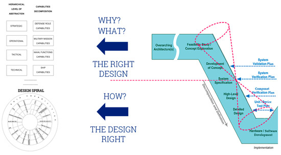
Figure 4.
The relationship between the design spiral and the V-model.
It is necessary to clarify that traditionally the ship design spiral models make use of a convergent spiral representation of the design process, ending with the ship to be built. However, some researchers developed divergent spiral models, such as the one developed by Rawson [33], which differs from the typical inward-spiraling approach and prefers an outward spiral, proposing a different perspective of the solution domain. The convergent representation, in fact, means that the final solution is reached after several iterative loops; while the divergent representation suggests an increase in complexity and details as the solution evolves, but still the solution converges in the final feasible product.
For all the ship’s typology, during the design spiral development, the payload integration is assessed in terms of space (volume and area), weight, electrical balance, local structural strength, and stability. However, for naval ships some other important integration issues are to be considered to overcome the dichotomy, very evident between the so-called platform and payload:
- Platform: it refers to the ship itself, including its hull, superstructure, propulsion systems, sensors, and other fundamental components. It is the physical vessel that serves as a foundation for carrying and deploying various types of payloads.
- Payload: it refers to the specific equipment, weaponry, sensors, and systems that are installed onboard the ship to carry out its mission operational objectives. For instance, they can be weapons like missiles, guns, torpedoes, or sensors like radar, sonar, or communication systems.
To this purpose starting from the Design Spiral defined by Watson in [10] (see also Figure 1), a new version is proposed in Figure 5 taking into account other integration issues such as:
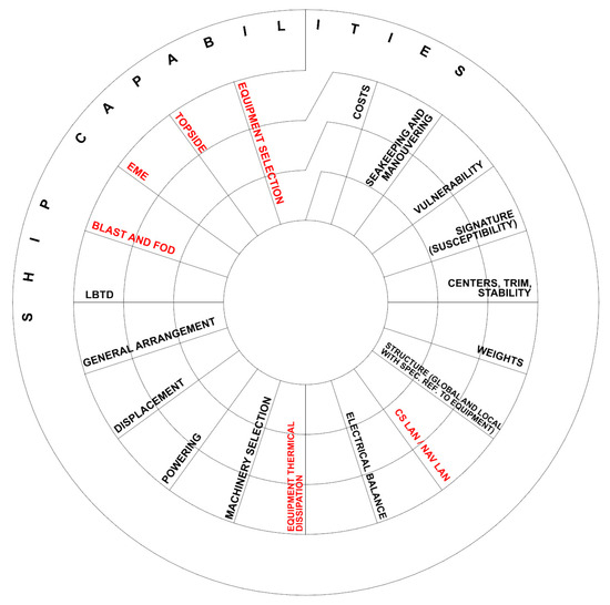
Figure 5.
Integration of payload aspects in the design spiral.
- Equipment selection: The selection of the systems/equipment that are necessary for the naval ship mission.
- Topside: This is where many key components are located along the ship length and it plays a crucial role in the ship’s functionality and combat capabilities. It involves the correct positioning of the payload systems with respect to each other, considering possible interferences between systems.
- EME: Electromagnetic Environment Effects refers to the impact of electromagnetic radiation, including radiofrequency emissions and other forms of electromagnetic energy, on the operation and performance of electronic systems and equipment on board a warship. Considerations on EME are critical to ensure the proper functioning and protection of electronic systems and equipment on board and to maintain operational effectiveness in a potentially hostile electronic warfare environment
- Equipment thermal dissipation: This refers to the management and control of heat generated by the various electronic and electrical equipment on board the warship, which is essential to effectively dissipate to ensure the reliable and safe functioning of these systems.
- Blast and FOD: Blast refers to the shock wave and pressure generated by the detonation of explosive devices. It is a significant concern in naval warfare, as blast effects can cause severe damage to the ship and its crew. Thus, warships are designed and equipped to withstand or mitigate the effects of blasts making use of reinforced hulls, blast-resistant compartments, and other protective measures. FOD (Foreign Object Debris or Foreign Object Damage) refers to any foreign object, substance, or debris that can enter or damage a warship’s systems, equipment, or machinery, potentially leading to equipment malfunction or damage. FOD considerations are crucial for maintenance and operation activities.
- CS LAN/NAV LAN: Combat System LAN (CS LAN) is a network dedicated to supporting the ship’s combat and weapons systems, which is used for coordinating and controlling the ship’s offensive and defensive capabilities, such as missile launch systems, gun mounts, radar, and other combat-related sensors and systems. Navigation LAN (NAV LAN) is a network established for the ship’s navigation and general ship management purposes. It typically includes navigation sensors, charts and mapping systems, GPS equipment, and communication systems necessary for the ship’s navigation and coordination with other vessels. These LANs are separate and distinct to ensure that combat systems and navigation functions are segregated for security and operational reasons, so it is necessary to well define the cable passage and positioning.
The above topics have been added as new rays (depicted in red in Figure 5) to the traditional design spiral for warships and they have been placed according to the necessary knowledge to be addressed in the design process. It is pointed out that they are not usually all involved during the first loops of the design spiral, but they are certainly taken into account when the knowledge level about details is appropriate in the further loops to properly merge the platform and the payload in a final feasible warship.
As stated above, the design spiral perfectly fits in the lower part of the V-Model left leg once the ship specifications have been defined. The proposed new version of the design spiral model is meant to better fit in the case of warship design and production.
Nevertheless, a robust procedure that creates an objective link between the needs and the ship requirements (input for the design spiral) is necessary. Moreover, a sound metric (MOE) that enables the mirroring of the ship’s performance and the fulfillment of the needs is of outstanding importance. In this paper, a capability-based approach is proposed in order to rationally guide the selection of the necessary requirements to define specifications and subsequently better instruct the design spiral method.
An example is the selection of the speed(s) requirement, which is usually already established when approaching the first Design Spiral steps. The selected speed(s), also in relation to the size of the ship, has a significant impact on the installed power and acquisition (CAPEX) and maintenance/operational (OPEX) costs. In this example, the proposed approach essentially facilitates an objective discussion about the required speed(s) for mission compliance and ensures a tangible connection between the chosen speed value and the underlying reasons for its selection.
To this aim, a decomposition of the capabilities is going to be postulated. The necessary level is the one that enables the definition of MOP.
Capability-based approaches are often used to manage the design of complex systems [32], being able to decompose and represent the whole system through its main functions and shifting the focus from the solution domain to the problem domain. This kind of approach enables the trade-off of different solutions early in the design process, allowing the selection of the right design with quantitative and objective evaluations.
Figure 6 shows a possible hierarchical model [34] to decompose the capabilities involved in the naval ship design process in the upper part of the V-Model left leg. The first set of capabilities (defense role, military mission, and operational) is strictly related to high-level evaluations of political strategies and the identifications of the military missions and operational capabilities needed to perform specific naval tasks required by the navy or the government. Those capabilities allow us to ultimately select the ship capabilities required to fulfill the operational requirements identified. Thus, it is in this phase that MOEs are selected to analyze the trade-off of different possible architectures and validate them to select the right ensemble of capabilities that the final solution should embed.
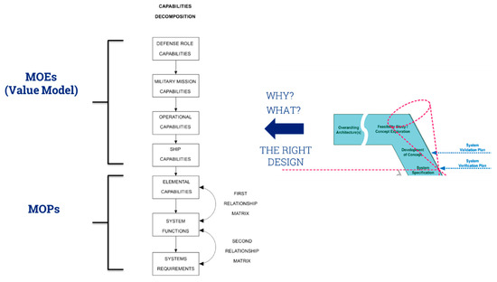
Figure 6.
Capability Decomposition for the P-Cone.
Hereafter an approach is proposed to manage the last groups of capabilities (ship capabilities and elemental capabilities), which are necessary to well describe what the ship should be, in order to define the specifications that will lead to the design spiral and the physical realization of the ship. Those particular capabilities represent the connection between the problem domain and the solution domain, where the two cones’ vertices meet. At this point, it is necessary to select the functions required for each capability to subsequently select appropriate high-level MOPs, which will be then used to verify that the selected capabilities are appropriately integrated during the first loop of the design spiral.
Referring to Figure 6, the main ship capabilities (Table 1), are divided into elemental capabilities, following the decomposition proposed by L. Tirone [35] and Guglielmi [36].

Table 1.
Main naval ship capabilities.
Those elemental capabilities represent the lower possible level of decomposition to describe a warship. Table A1 (Appendix A) reports the platform elemental capabilities, with their naval intent, here introduced to describe in detail the functions enabled by each capability, and the satisfaction level. The same for the payload elemental capabilities in Table A2 (Appendix A). The satisfaction level must be selected from the proposed ones in order to appropriately select the functions that are required to accomplish the operational capabilities derived by the previous political and strategic studies.
When the satisfaction level and the required functions have been identified, it would be possible to in turn appropriately define high-level MOPs. These KPIs will be used in the next design stages to assess the integration of the platform and payload capabilities in the naval ship under design. Moreover, the selected MOPs will enable tracking the impact of both payload and platform on specific topics of the Design Spiral, making it possible to define a hinge between the two realms and put the basis for a novel comprehensive approach where they are finally interconnected with each other.
The proposed approach aims to establish a solid theoretical foundation. However, for efficient implementation in the design process, future developments will require the application of a modeling tool, utilizing powerful instruments like Model-Based Systems Engineering (MBSE) softwares. Simultaneously, within the context of evaluating the ship’s performance at both MOPs and MOEs levels, it is crucial to emphasize the significance of numerical applications. These applications, such as CAD/FEM/CFD, are already state-of-the-art in handling crucial design spiral steps, and their efficient integration into the proposed approach is also desirable.
5. Conclusions
The shortcomings of the traditional but still fundamental design spiral together with the evident complexity of a warship emphasize the need for an evolution of the naval ship design process with a wider vision: from the requirements definition to the delivery of the final product.
An integration of the traditional design spiral linear iterative model and the SE V-model has been described, supported by the discussion of an integration methodology based on a capability-based approach. The capabilities decomposition permits to well describe the functionalities that the desired naval ship should embody, both in terms of Platform and Payload.
The important outcome is the possibility to define, starting from the selected levels of satisfaction, metrics (MOPs) that allow the assessment of ship/systems performance in the key SE process of verification. MOEs for the validation processes should be defined on a higher level according to the definition of the strategic and mission capabilities.
An extended ship design spiral has been proposed, with the integration of new rays relevant to the payload performance when acting onboard. Those rays represent important gates, which take place at their intersection with the spiral loops, where the MOPs can be used for the capabilities assessment.
The proposed approach aims to define the first theoretical steps in the process to define a novel approach exploiting the design spiral and systems engineering, starting with the identification of the ship’s platform and payload capabilities. The methodology appears a good support for bridging the two different domains, a traditional still unsolved challenge in naval ship design.
The proposed approach will be applied to a selected case study to assess the satisfaction level for each capability required for a Maritime Interdiction Operation (MIO) naval task. Identifying the necessary level for each elemental capability will then facilitate the selection of the relevant MOPs and their target values. This step is crucial for establishing the technical requirements at the intersection of the two cones.
Nevertheless, there appears a need to further develop the methodology by means of the selection of a modeling tool, which could enable a more agile structuring process and a more effective benefit acquisition for a more usable and practical application.
Author Contributions
Conceptualization, M.B. and P.G.; Methodology, M.B. and P.G.; Writing—original draft, M.B.; Writing—review & editing, P.G.; Supervision, P.G. All authors have read and agreed to the published version of the manuscript.
Funding
This research received no external funding.
Data Availability Statement
Data sharing is not applicable. No new data were created or analyzed in this study.
Conflicts of Interest
The authors declare no conflict of interest.
Appendix A
Hereafter are reported the tables showing the decomposition of the Ship Capabilities into Elemental Capabilities and their relative levels of satisfaction.
Table A1.
Levels of Satisfaction for the Platform Elemental Capabilities.
Table A1.
Levels of Satisfaction for the Platform Elemental Capabilities.
| Ship Capability | Elemental Capability | Naval Intent | Satisfaction Level | |
|---|---|---|---|---|
| BUOYANCY | BASE BUOYANCY | Ability to sustain the weight of onboard equipment, person and consumables in intact state | 0 | Buoyancy sufficient for Platform and necessary Payload |
| 1 | Draft suitable for intended operational waters and harbors/suitable for propeller immersion/suitable for slamming avoidance | |||
| BUOYANCY RESERVE | Ability to sustain the weight of non-organic onboard loads or flooding | 0 | Buoyancy sufficient for end-of-life load condition | |
| 1 | Possible change of weight with reference to systems renewal against obsolescence | |||
| 2 | Possible change of weight with reference to operability by different modular units onboard | |||
| 3 | Reserve of buoyancy compatible with survivability of the ship in damaged condition | |||
| 4 | Reserve of buoyancy compatible with navigation in damaged condition | |||
| 5 | Reserve of buoyancy compatible with combat activity in damaged condition | |||
| EVEN KEEL WATERLINE BUOYANCY | Ability to distribute weights in order to maintain the Center of Gravity in line with the Center of Buoyancy | 0 | Suitable trim/heel for smooth operation onboard | |
| 1 | Suitable trim/heel for better hydrodynamic performance (resistance and seakeeping) | |||
| 2 | Suitable trim/heel for propeller immersion and slamming avoidance | |||
| STABILITY | INTACT STABILITY | Ability to resist inclining actions in intact conditions | 0 | Compliance with general criteria for stability |
| 1 | Sufficient stability (roll motion amplitude and accelerations) until Sea State 3 (100% functions) | |||
| 2 | Sufficient stability (roll motion amplitude and accelerations) until Sea State 4 (percentage of degrade function TBD) | |||
| 3 | Sufficient stability (roll motion amplitude and accelerations) until Sea State 5 (percentage of degrade function TBD) | |||
| … | … | |||
| 6 | Compliance with special inclining moments | |||
| DAMAGED STABILITY | Ability to resist to inclining actions after a damaging event | 0 | Compliance with criteria for stability in damaged condition (survivability) | |
| 1 | Residual stability compatible with navigation | |||
| 2 | Residual stability compatible with combat activity | |||
| STRUCTURAL STRENGTH | GLOBAL STRUCTURAL STRENGTH | The ability to resist the stress created by the weight distribution along the ship length, the buoyancy given by the submerged watertight hull, in calm water, and in waves. | 0 | Compliance with Steel water and wave bending moment |
| 1 | Global structural strength compatible with Sea State X | |||
| 2 | Withstand the impact of either a surface/surface missile or a naval gun | |||
| 3 | Withstand an internal blast (temporary overpressure caused by an internal explosion of a missile warhead) | |||
| 4 | Withstand a non-contact underwater explosion | |||
| LOCAL STRUCTURAL STRENGTH | Ability to resist specific local loads | 0 | Compliance with local strength assessment requirements | |
| 1 | Local structural strength compatible with Sea State X | |||
| 2 | Withstand slamming dynamic loads (and relevant whipping at a global level) | |||
| 3 | Withstand an external blast (temporary overpressure caused by an explosion outside the vessel)—superstructures | |||
| 4 | Withstand a certain class of fragments (bodies with mass and speed usually generated by an explosion of a missile warhead or a gunshot) | |||
| POWER GENERATION | PROPULSION POWER GENERATION | Ability to generate the necessary power for the Vessel’s propulsion | 0 | Power for Endurance Speed and Maximum Speed |
| 1 | Power for Endurance Speed with Sea State X | |||
| 2 | Power for Maximum Speed with Sea State X | |||
| EQUIPMENT POWER GENERATION | Ability to generate electrical power for all appliances, such as utilities, combat system, navigation, comm., etc. | 0 | Electrical power for all systems in intact state | |
| 1 | Electrical power to supply X % of systems in specified damaged condition | |||
| EMERGENCY POWER GENERATION | Ability to provide power under emergency or degraded conditions | 0 | No Emergency Power Generation | |
| 1 | Power generation for specified emergency systems onboard (self-defense systems included) | |||
| 2 | Power generation for take-me-home system | |||
| CONTROLLABILITY | PROPULSION | Ability to convert generated power into Vessel’s speed | 0 | Maintain Endurance Speed and Maximum Speed |
| 1 | Maintain Endurance Speed with Sea State X | |||
| 2 | Maintain Maximum Speed with Sea State X | |||
| STEERING | Ability to modify the heading of the Vessel | 0 | Compliance with standard maneuverability requirements | |
| 1 | Route stability in unmanned mode | |||
| 2 | Dynamic positioning level 1 | |||
| 3 | Dynamic positioning level 2 | |||
| COMM. | INTERNAL COMMUNICATIONS | Ability to manage the exchanges of information internally among the Warship components | 0 | Ordinary Public Address |
| 1 | Emergency Public Address | |||
| 2 | LAN (Local Area Network) | |||
Table A2.
Levels of Satisfaction for the Payload Elemental Capabilities.
Table A2.
Levels of Satisfaction for the Payload Elemental Capabilities.
| Ship Capability | Elemental Capability | Naval Intent | Satisfaction Level | |
|---|---|---|---|---|
| NAVIGATION | SENSING | Ability to acquire information about the Warship position, heading, motion and attitude, and the operational environment surrounding it | 0 | Acquire information about the position |
| Acquire information about heading | ||||
| Acquire information about speed | ||||
| Acquire information about ship attitude and motion | ||||
| Acquire information about environmental features (wind) | ||||
| Acquire information about environmental features (water depth, current) | ||||
| Acquire information about environmental features (distance from other ships, distance from the coast) | ||||
| 1 | Acquire information about environmental features (waves) | |||
| 2 | Spill oil detection | |||
| ROUTE PLANNING | Ability to plan and establish the Warship route. Wind, waves, currents, and sea ice cover are crucial factors in choosing a route at sea. | 0 | Planning ship routes | |
| 1 | Planning ship routes for low-consumption | |||
| 2 | Planning ship routes with reference to weather conditions | |||
| 3 | Planning ship routes for special purposes | |||
| COMMAND AND CONTROL | MARITIME PICTURE COMPILATION/SITUATION ASSESSMENT | Ability to process the data received from passive and active sensors, from Data Links, and from manual insertion by Operators. | 0 | Maritime Picture Compilation is the Capability to process the data received from passive and active sensors, from Data Links, and from manual insertion by Operators. The scope is to display to the Operator a unique representation of the Real-World Objects (RWOs) around the Warship. Situation Assessment is the Capability to identify and classify, based on a Maritime Picture Compilation, any tracks in the maritime picture as friends or possible threats. Many track functionalities for identification are necessary: initialization, association, coupling, |
| 1 | Data Link | |||
| ENGAGEMENT | 0 | Engagement for single-threat | ||
| 1 | Engagement for multiple threats (manual) | |||
| 2 | Engagement for multiple threats (automatic) | |||
| SUPPORT | Ability to monitor and control the status of organic equipment, including the management of alarms and the control of electromagnetic emissions | 0 | Resource Management is the Capability to monitor and control the status of organic equipment, including the management of alarms and the control of electromagnetic emissions. Data Recording and Analysis is the Capability to store, extract, and process data exchanged among all Warship equipment. Support to Navigation is the Capability to support safe navigation of the Warship through navigation aids management. Mission Planning is the capability to define mission parameters and relevant data for the Warship. Training is the Capability to simulate possible scenarios in which the Warship could be involved in order to support Operator training. | |
| 1 | Post Mission Analysis is the Capability to analyze mission recorded data for the purpose of validating actions taken during the tactical phase, potentially generating new contact data based on discovered missed detection/classification opportunities. | |||
| 2 | Approach Control is the Capability to support aircraft operations, including approach, deck landing and take-off. | |||
| 3 | Support Services is the Capability to provide support services such as mail, intranet, data processing | |||
| 4 | UXV Management is the Capability to manage Unmanned Aerial, Surface, or Underwater Vehicles operations. | |||
| 5 | Air Traffic Control is the capability to direct air traffic in coordination with ATC centers. | |||
| EXTERNAL COMM. | EXTERNAL COMMUNICATIONS | Ability to manage the exchanges of information with other units or land centers to receive data and orders and participate as a force asset | 0 | Safety and distress communication systems, in accordance with IMO regulations |
| 0 | External services for shore and other ships communications in a medium-short range distance | |||
| 1 | External services for shore and other ships communications in a long-range distance | |||
| 2 | External services for communication with subsidiaries assets (unmanned vehicles, helicopters, etc.) | |||
| 2 | Public Service satellite communication (WAN) | |||
| 3 | Tactical Data Link | |||
| 4 | Private/Government satellite communication (WAN) | |||
| 4 | External services for submarine communication | |||
| 4 | External services for underwater communication (acoustic communication system) | |||
| SURVEILLANCE | ABS ABOVE WATER SURVEILLANCE | Ability to detect air-based objects (such as aircraft, or missiles) and surface vessels. | 0 | Surveillance to visual range |
| 1 | Surveillance to the horizon | |||
| 2 | Surveillance beyond the horizon | |||
| UWS UNDER WATER SURVEILLANCE | Ability to detect underwater objects, such as submarines or mines. | 0 | Obstacle avoidance in shallow waters | |
| 1 | Passive UW surveillance | |||
| 2 | Active UW surveillance | |||
| COMBAT | AAW ANTI-AIR WARFARE | Ability to deny the enemy the effective use of threats that originate from air: aircrafts, helicopters, missiles, UAV. | 0 | No AAW capability |
| 1 | Limited surveillance and reconnaissance, and short-range self-defense capabilities (e.g., CIWS/PDMS) | |||
| 2 | Self-defense capabilities (i.e., Inner Layer Defence System (ILDS)) | |||
| 3 | Extended Self-defense capabilities (i.e., Limited Outer Layer Defense System (OLDS)) | |||
| 4 | Area Defense capabilities (i.e., OLDS) | |||
| 5 | Defense against ballistic missile | |||
| ASUW ANTI-SURFACE WARFARE | Ability to deny the enemy the effective use of threats that originate from surface vessels. | 0 | No ASuW capability | |
| 1 | Limited surveillance and reconnaissance, short-range (up to 3 km) self-defense ASuW capability (e.g., 40 mm Guns) | |||
| 2 | Medium range (up to 7.5 km) self-defense ASuW capability (e.g., 76 mm Gun) | |||
| 3 | Extended range (up to 11 km) self-defense ASuW capability | |||
| 4 | Offensive to-the-horizon ASuW capability | |||
| 5 | Offensive over-the-horizon ASuW capability | |||
| ASW ANTI-SUBMARINE WARFARE | Ability to deny the enemy the effective use of threats that originate below the water surface by submarines | 0 | No ASW capability | |
| 1 | Limited self-defensive capabilities against submarine threats (Anti-Ship Torpedo Defense) | |||
| 2 | Self-defensive and offensive capabilities against submarine threats inside own sensors’ range | |||
| 3 | Extended ASW capability at standoff distances (e.g., ASW-capable helicopter) | |||
| 4 | Area ASW Coordination and Offensive capability (long-range sensors, standoff weapons, and ASW capable helicopter) | |||
| ELECTRONIC WARFARE | Ability to deny the enemy the effective use of threats that affect the electromagnetic spectrum: Electronic Attack Measures and Electronic Protection Measures | 0 | No EW capability | |
| 1 | Self-defense EW alarm capability (e.g., warning receivers) | |||
| 2 | EW alarm & analysis capability (e.g., direction finding, classification) | |||
| 3 | On-board Self Defense EW alarm, analysis, and passive CM capability | |||
| 4 | On-board Self Defense EW alarm, analysis, and CM capability (active & passive) | |||
| 5 | On-board Local Area Defense EW Suite capability | |||
| MCM MINE-COUNTERMEASURES | Ability to detect and neutralize above-water and underwater mines or other items | 0 | Reducing the risk of applying all self-protection measures (i.e., degaussing, acoustic silencing, MAS) | |
| 1 | Conduct some specific tasks not considered MCM Operations (e.g., surveys and lead-through) | |||
| 2 | Conduct some MCM Operations limited to Detection, Localization, and Classification of mine-like contacts | |||
| 3 | Conduct some MCM Operations limited to Detection, Localization, Classification, and Identification of mine/NOMBO | |||
| 4 | Conduct limited countermining operations | |||
References
- Andrews, D. A comprehensive methodology for the design of ships (and other complex systems). Proc. R. Soc. A 1998, 454, 187–211. [Google Scholar] [CrossRef]
- Clemens, M. The Characteristics of Complex Systems; New England Complex Systems Institute: Cambridge, MA, USA, 2019. [Google Scholar]
- Papanikolaou, A. A Holistic Approach to Ship Design Volume 1: Optimization of Ship Design and Operation for Life Cycle; Springer: Berlin/Heidelberg, Germany, 2019. [Google Scholar]
- Singer, D.J.; Doerry, N.; Buckley, M.E. What is set based design? Nav. Eng. J. 2009, 121, 31–43. [Google Scholar] [CrossRef]
- Guégan, A.; Rafine, B.; Descombes, L.; Fadiaw, H.; Marty, P.; Corrignan, P. A systems engineering approach to ship design. In Proceedings of the 8th International Conference on Complex Systems Design & Management, Paris, France, 12–13 December 2017. [Google Scholar]
- Fernandez, R.P. A New Approach for Using Cad and Plm Integration. In Proceedings of the International Conference on Computer Applications in Shipbuilding (ICCAS), Yokohama, Japan, 13–15 September 2022. [Google Scholar]
- Matsuo, K. Development of PLM system for precise production planning and production control in shipbuilding. In Proceedings of the International Conference on Computer Applications in Shipbuilding (ICCAS), Yokohama, Japan, 13–15 September 2022. [Google Scholar]
- Andrews, D.J. Simulation and the Design Building Block Approach in the Design of Ships and Other Complex Systems. Proc. R. Soc. A Math. Phys. Eng. Sci. 2006, 462, 3407–3433. [Google Scholar] [CrossRef]
- Evans, J. Basic design concepts. J. Am. Soc. Nav. Eng. 1959, 71, 671–678. [Google Scholar] [CrossRef]
- Watson, D. Practical Ship Design; Elsevier: Amsterdam, The Netherlands, 1998; Volume 1. [Google Scholar]
- Levander, K. Innovative ship design—Can innovative ships be designed in a methodological way. In Proceedings of the 8th International Marine Design Conference—IMDC03, Athens, Greece, 5–8 May 2003. [Google Scholar]
- Papanikolaou, A.; Andersen, P.; Kristensen, H.; Levander, K.; Riska, K.; Singer, D.; Vassalos, D. State of the art on design for X. In Proceedings of the 10th International Marine Design Conference IMDC09, Trondheim, Norway, 16–19 May 2009. [Google Scholar]
- Andrews, D. (Ed.) State of the Art Report on Design Methodology. In Proceedings of the 10th International Marine Design Conference IMDC 2009, Trondheim, Norway, 16–19 May 2009. [Google Scholar]
- Andrews, D. (Ed.) State of the Art Report on Design Methodology. In Proceedings of the 11th International Marine Design Conference IMDC 2012, Glasgow, UK, 11–14 June 2012. [Google Scholar]
- Andrews, D.; Erikstad, S.O. State of the Art Report on Design Methodology. In Proceedings of the 12th International Marine Design Conference IMDC 2015, Tokyo, Japan, 11–14 May 2015. [Google Scholar]
- Andrews, D. The Sophistication of Early Stage Design for Complex Vessels. Trans RINA Part A Int. J. Marit. Eng. 2018, 160. [Google Scholar] [CrossRef]
- Brown, A.; Thomas, M. Reengineering the Naval Ship Concept Design Process; From Research to Reality in Ship Systems Engineering Symposium; ASNE: Alexandria, VA, USA, 1998. [Google Scholar]
- Bruinessen, T.; Hopman, H.; Smulders, F. Towards a Different View on Ship Design: The Development of Ships Observed Through a Social-Technological Perspective. In Proceedings of the ASME 2013 32nd International Conference on Ocean, Offshore and Arctic Engineering, Nantes, France, 9–14 June 2013. [Google Scholar]
- Brown, A. Defining a Warship. Nav. Eng. J. 1986, 98, 31–40. [Google Scholar]
- Walden, D.; Roedler, G.; Forsberg, K.; Hamelin, D.; Shortell, T. Systems Engineering Handbook, 4th ed.; International Council on Systems Engineering; Wiley: Hoboken, NJ, USA, 2015. [Google Scholar]
- Federal Aviation Administration. FAA Systems Engineering Manual; Federal Aviation Administration: Washington, DC, USA, 2014. [Google Scholar]
- Katz, T.; Orr, K.; Wheatcraft, L. Guide to Needs and Requirements; International Council on Systems Engineering Report; INCOSE: San Diego, CA, USA, 2022. [Google Scholar]
- Federal Highway Administration. Systems Engineering for Intelligent Transportation Systems: An Introduction for Transportation Professionals; U.S. Department of Transportation: Washington, DC, USA, 2007. [Google Scholar]
- Roedler, G.; Lockheed, M.; Jones, C.; US ARMY. Technical Measurement—A Collaborative Project of PSM, INCOSE, and Industry; INCOSE—International Council On Systems Engineering: San Diego, CA, USA, 2005. [Google Scholar]
- Andrews, D. Art and science in the design of physically large and complex systems. Proc. R. Soc. A Math. Phys. Eng. Sci. 2012, 468, 891–912. [Google Scholar] [CrossRef]
- Gaspar, H.M.; Ross, A.M.; Rhodes, D.H.; Erikstad, S.O. Handling Complexity Aspects in Conceptual Ship De-sign. In Proceedings of the 11th International Marine Design Conference (IMDC), Glasgow, UK, 11–14 June 2012. [Google Scholar]
- Brown, A.J. Application of Operational Effectiveness Models in Naval Ship concept exploration and design. Cienc. Tecnol. Buques 2013, 7, 9–21. [Google Scholar] [CrossRef][Green Version]
- Brown, A.J.; Salcedo, J. Multiple-Objective Optimization in Naval Ship Design. Nav. Eng. J. 2003, 115, 49–62. [Google Scholar] [CrossRef]
- Bottero, M.; Gualeni, P. Capability-Based Approach for Naval Ships Design: A Metric Formulation. In Proceedings of the 14th International Marine Design Conference (IMDC 22), Vancouver, BC, Canada, 26–30 June 2022. [Google Scholar]
- Forsberg, K.; Mooz, H. The Relationship of System Engineering to the Project Cycle. In Proceedings of the National Council for Systems Engineering (NCOSE) Conference, Chattanooga, TN, USA, 21–23 October 1991; pp. 57–65. [Google Scholar]
- Bottero, M.; Gualeni, P. Systems Engineering and Ship Design: A synergy for getting the right design and the design right. In Proceedings of the 20th International Conference on Ship & Maritime Research (NAV 22), Genova, Italy, 15–17 June 2022. [Google Scholar]
- Papanikolaou, A. Ship Design: Methodologies of Preliminary Design; Springer: Berlin/Heidelberg, Germany, 2014. [Google Scholar]
- Rawson, K. The Architecture of Marine Systems. IEE Proc. A Phys. Sci. Meas. Instrum. Manag. Educ. Rev. 1986, 133, 333–337. [Google Scholar]
- Olivier, J.P.; Balestrini-Robinson, S. Capability-Based System-of-Systems Approach in Support of Complex Naval Ship Design. In Proceedings of the Fifth International Conference on Complex Systems Design & Management CSDM 2014, Paris, France, 12–14 November 2014. [Google Scholar]
- Tirone, L.; Gualeni, P.; Scognamiglio, M.G.; Bonofiglio, P. A Capability Based Approach for Warship Design. In Proceedings of the 16th International Conference on Systems (ICONS), Porto, Portugal, 18–22 April 2021. [Google Scholar]
- Guglielmi, J.; Gualeni, P.; Angeloni, A. Approccio Sistemico per L’analisi Delle Funzionalità di Un’unità Militare Per la Scelta e L’integrazione del Sistema di Combattimento. Master’s Thesis, DITEN—University of Genoa, Genoa, Italy, 2020. [Google Scholar]
Disclaimer/Publisher’s Note: The statements, opinions and data contained in all publications are solely those of the individual author(s) and contributor(s) and not of MDPI and/or the editor(s). MDPI and/or the editor(s) disclaim responsibility for any injury to people or property resulting from any ideas, methods, instructions or products referred to in the content. |
© 2024 by the authors. Licensee MDPI, Basel, Switzerland. This article is an open access article distributed under the terms and conditions of the Creative Commons Attribution (CC BY) license (https://creativecommons.org/licenses/by/4.0/).