
Visual-Aided Shared Control of Semi-Autonomous Underwater Vehicle for Efficient Underwater Grasping


Abstract
:1. Introduction
- The proposed method takes full advantage of human command in the high-level guidance, and the visual servo autonomy in the close-range dynamic positioning, to construct a stable, flexible and efficient shared controller for underwater grasping tasks.
- A variable AF of the target objects is proposed, whose field intensity is adjusted by the human intention extracted from the remote commands. An arbitration mechanism is then adopted to assign authority weights to the human command and the automatic controller according to the AF intensity.
- The shared controller is realized based on the reference velocity fusion in the kinematic level, which is then tracked by the dynamic controller considering model parameter uncertainties. Both the simulation and experiment demonstrate an obvious increase in the grasping efficiency and stability.
2. System Construction and Modeling
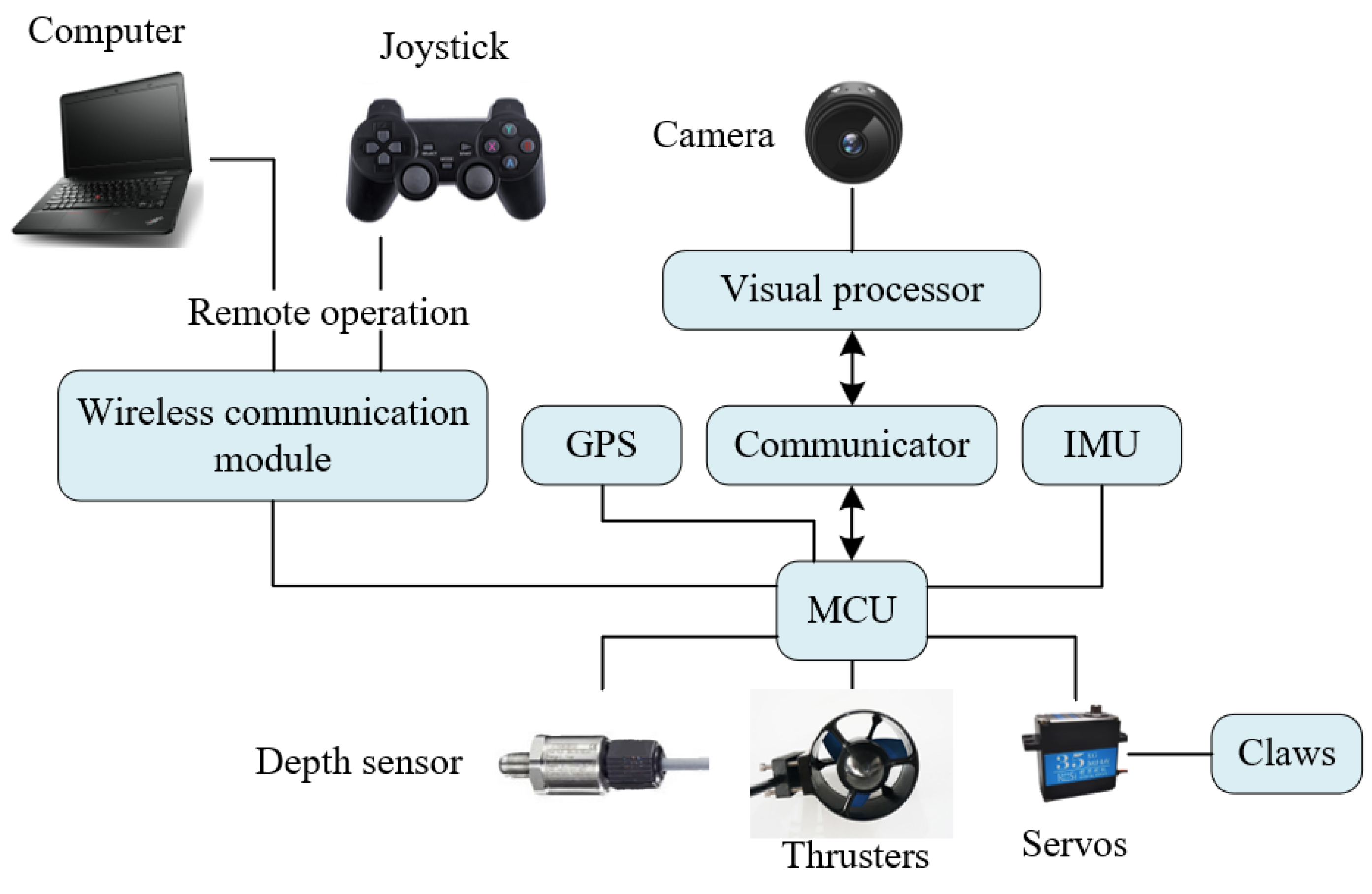
2.1. System Construction
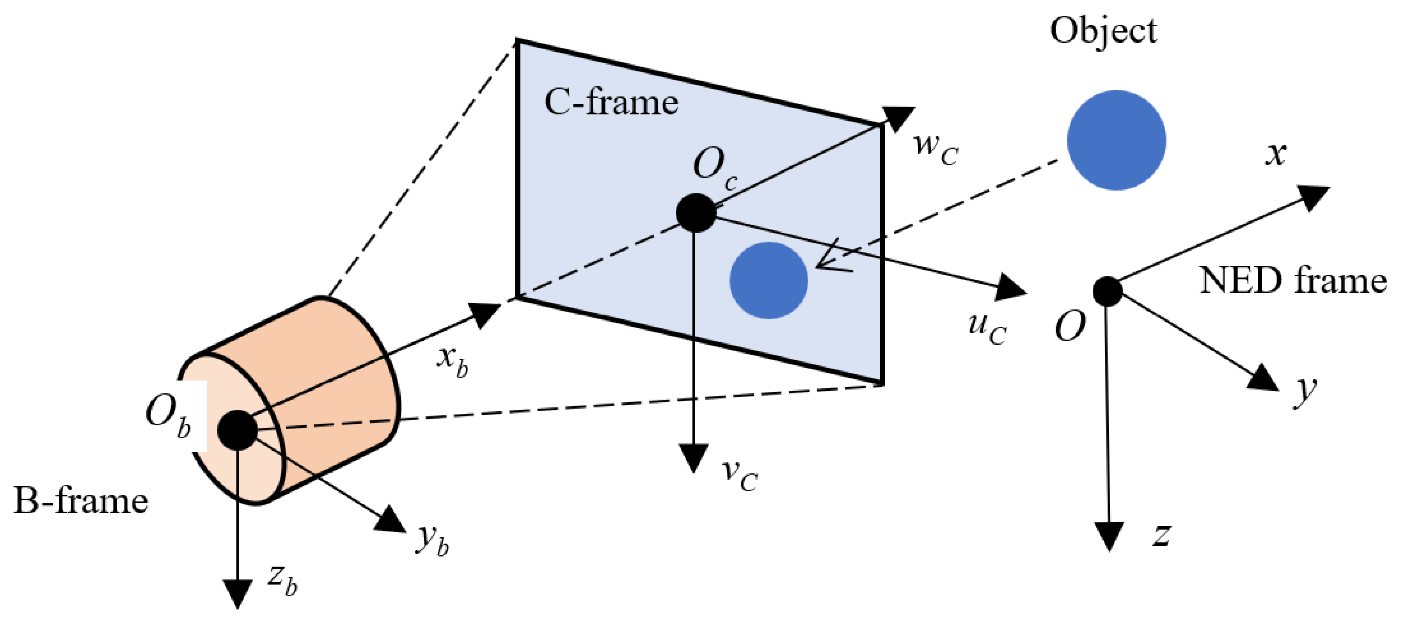
2.2. Kinematic Model
2.3. Dynamic Model
3. Shared Controller Design
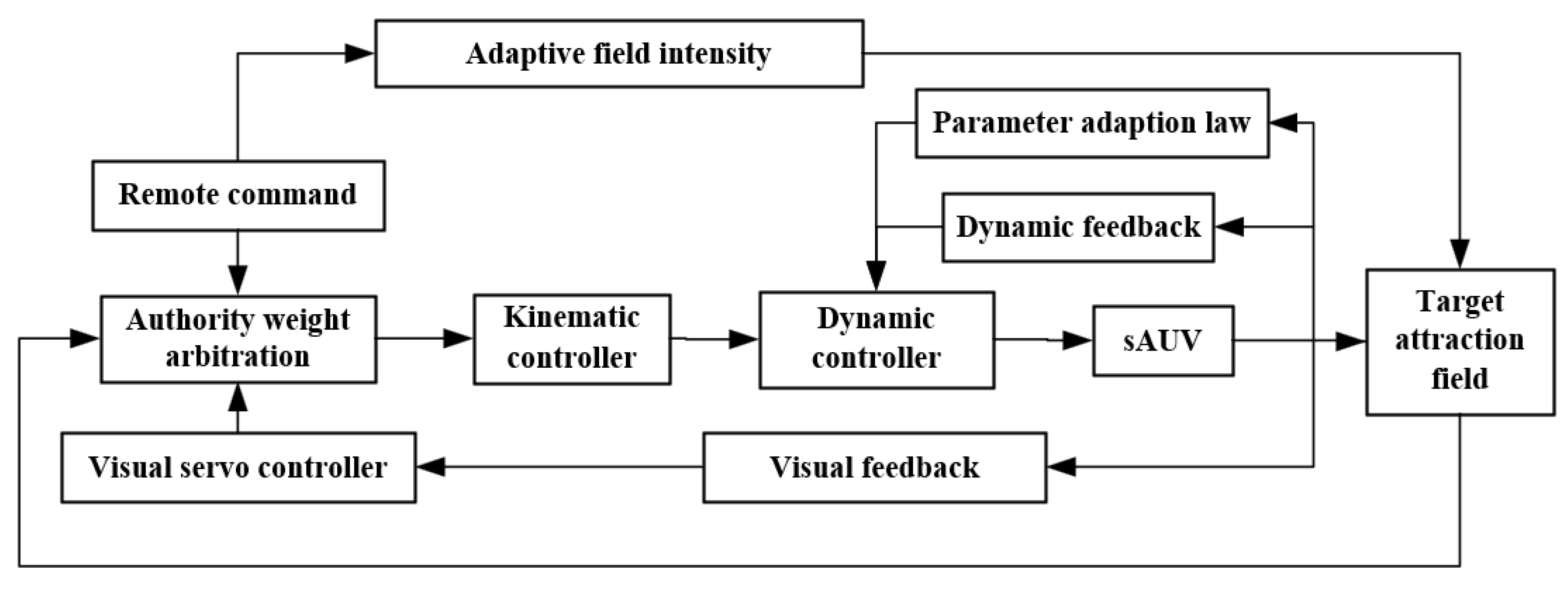
3.1. Shared Control Based on Attraction Field
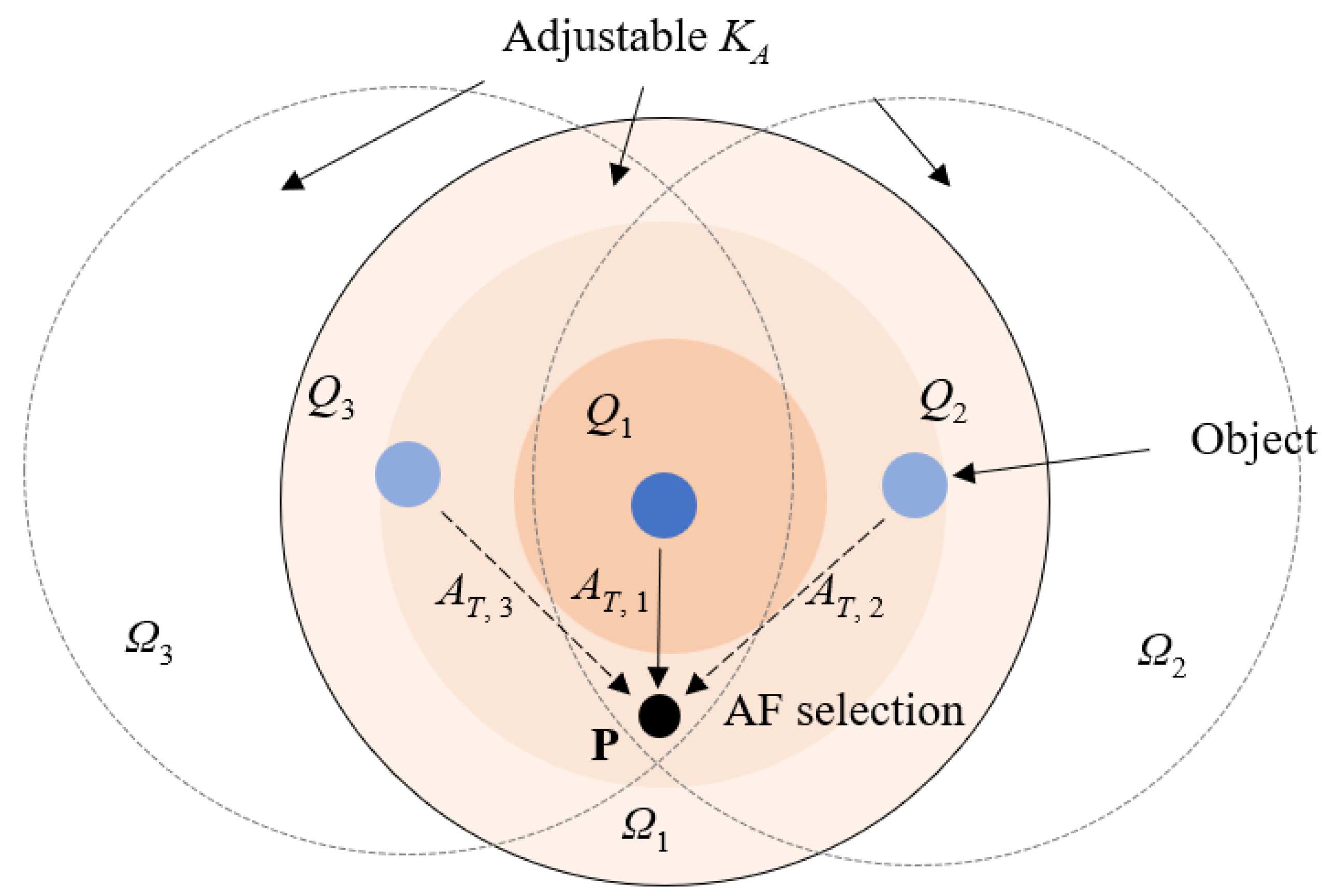
- Assuming that the active AF at the last sample time T − 1 comes from Qi and has an intensity of at the current time T. If the current AF with the largest intensity satisfies:where (1 + Hs) > 1 is the threshold ratio, the AF at time T is then switched to AT,1, and the corresponding source object is Q1 also selected.
- Otherwise, the resultant AF is still calculated using the object Qi at time T.
3.2. Dynamic Controller
4. Simulation and Experiment
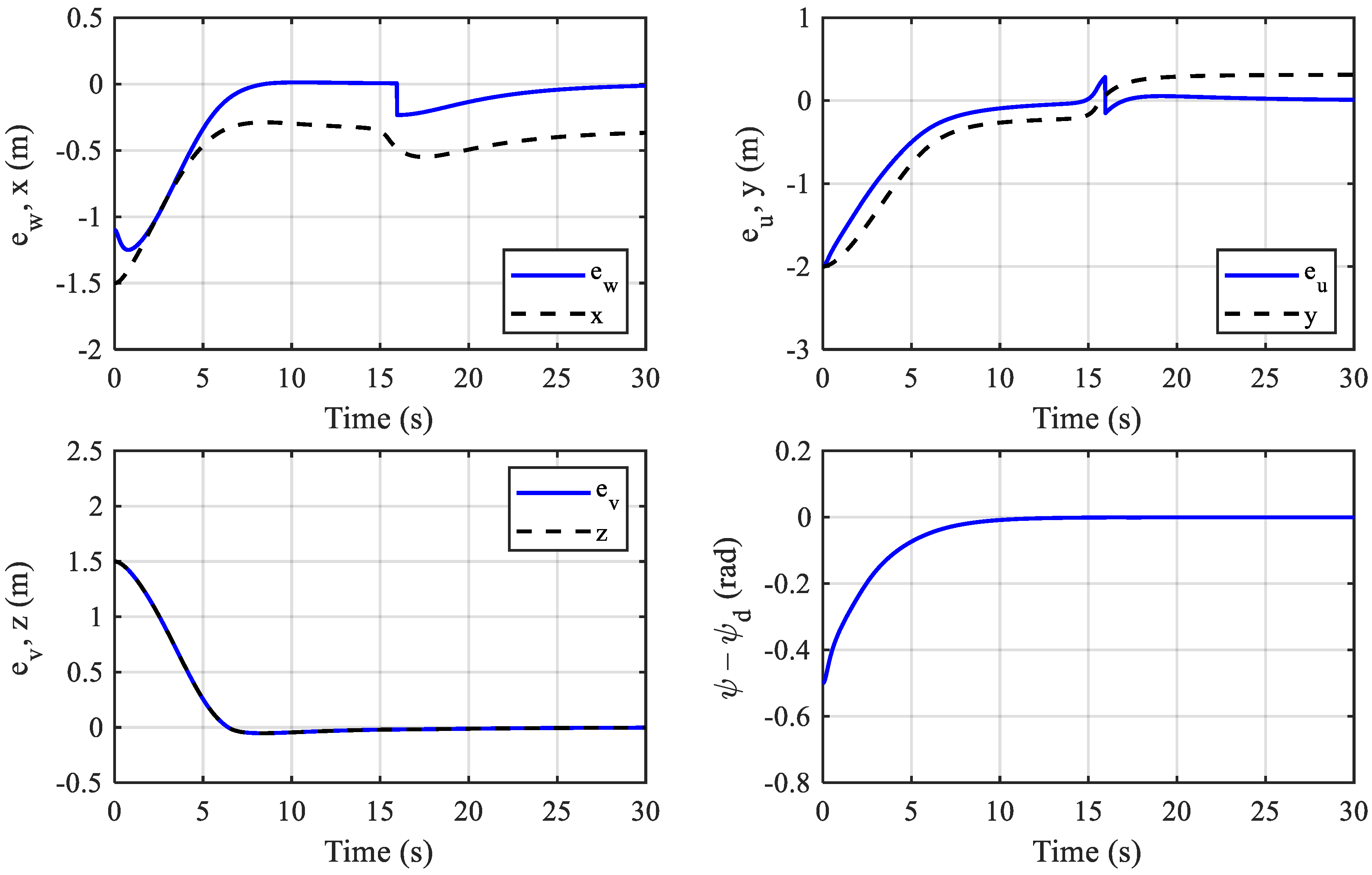
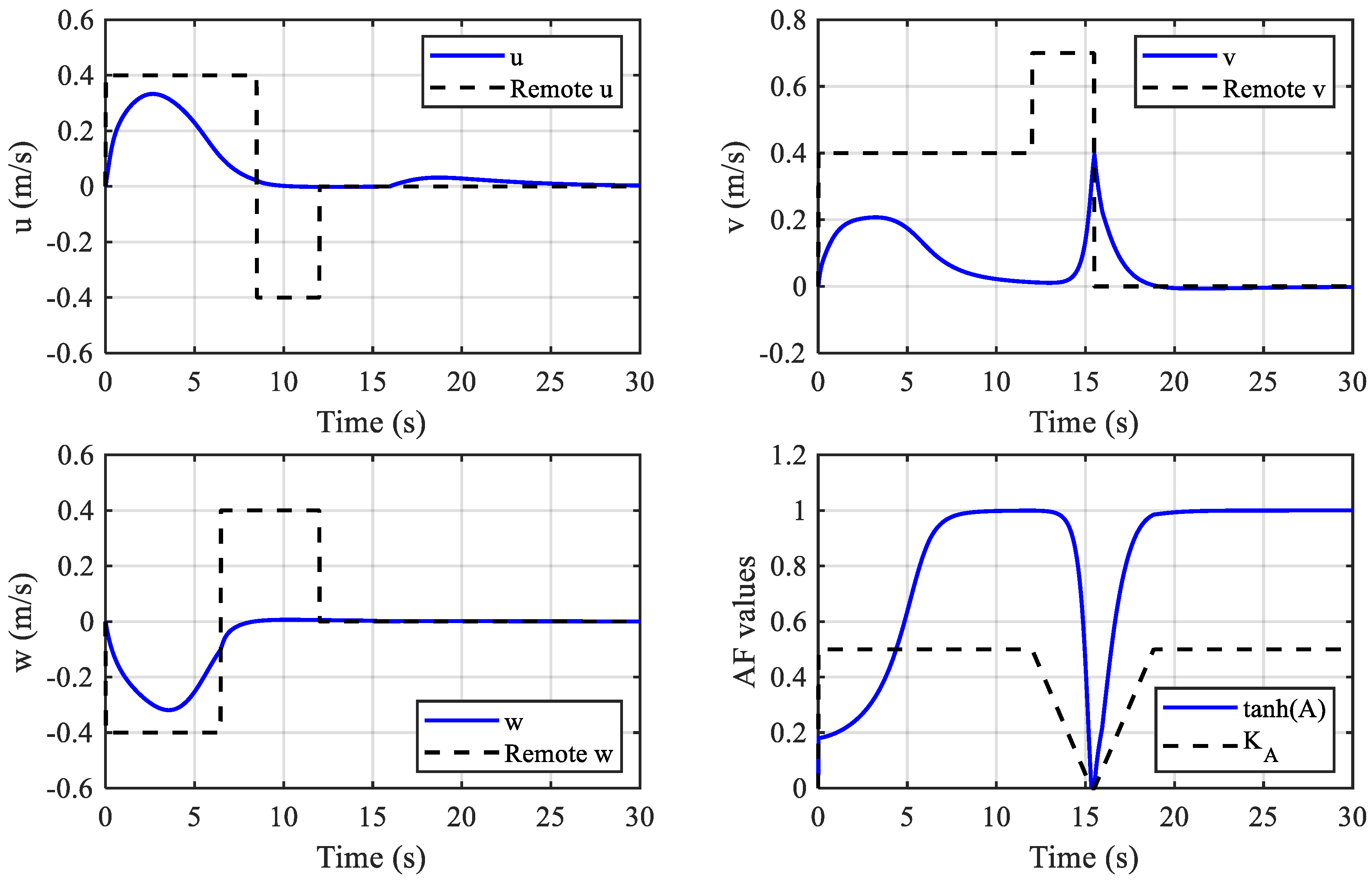
4.1. Simulation
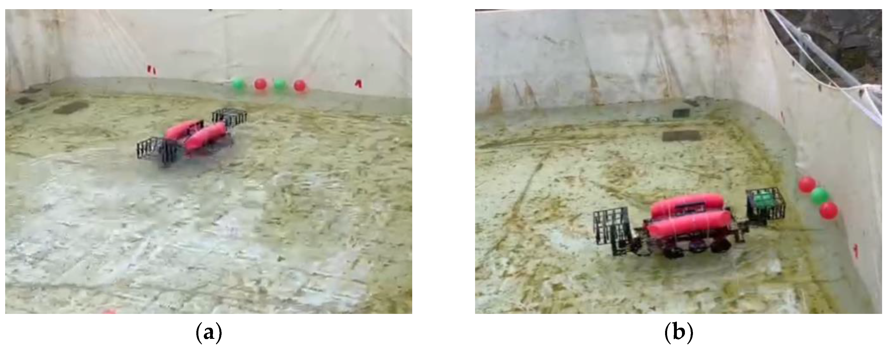
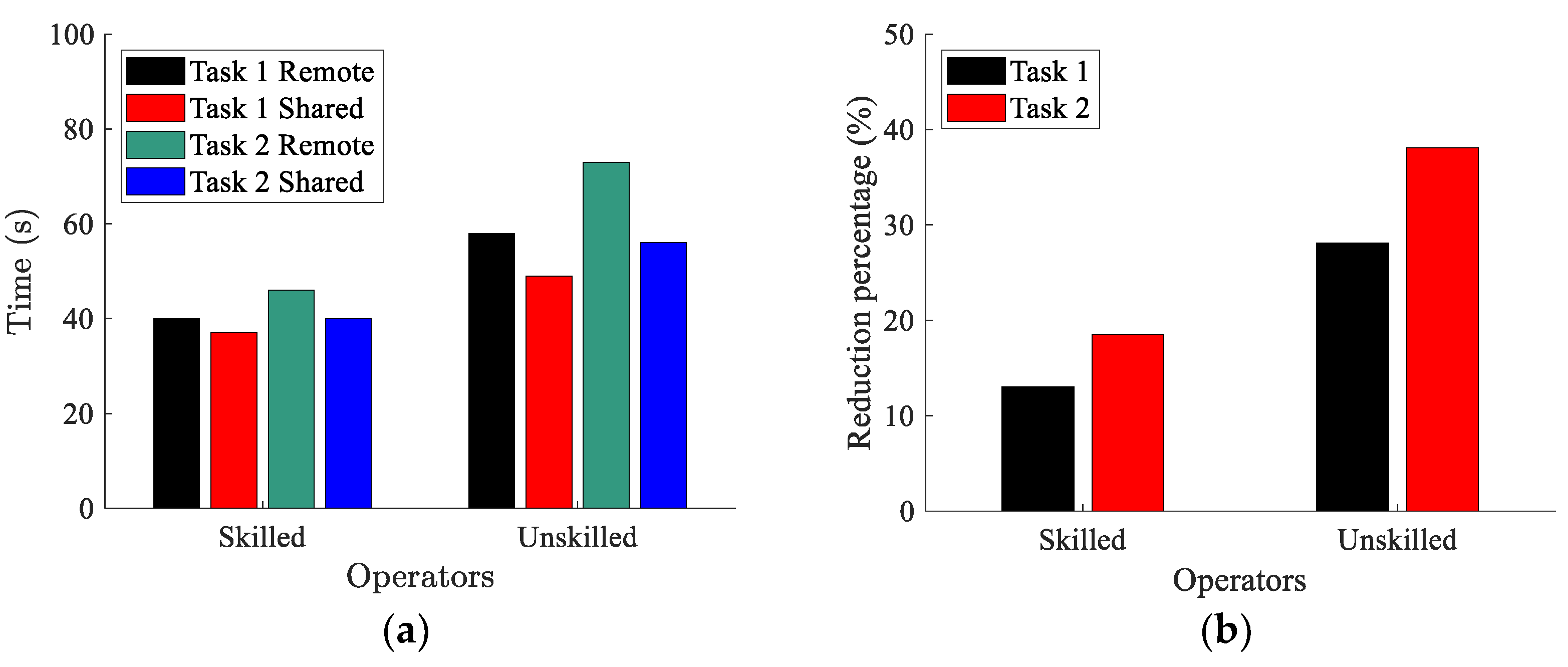
4.2. Experiment
5. Conclusions
Author Contributions
Funding
Institutional Review Board Statement
Informed Consent Statement
Data Availability Statement
Conflicts of Interest
References
- Sahoo, A.; Dwivedy, S.K.; Robi, P.S. Advancements in the field of autonomous underwater vehicle. Ocean Eng. 2019, 181, 145–160. [Google Scholar] [CrossRef]
- Wang, T.; Zhao, Q.; Yang, C. Visual navigation and docking for a planar type AUV docking and charging system. Ocean Eng. 2021, 224, 108744. [Google Scholar] [CrossRef]
- Hong, S.; Chung, D.; Kim, J.; Kim, Y.; Kim, A.; Yoon, H.K. In-water visual ship hull inspection using a hover-capable underwater vehicle with stereo vision. J. Field Robot. 2018, 36, 531–546. [Google Scholar] [CrossRef]
- Peng, Z.; Wang, J.; Han, Q. Path-Following Control of Autonomous Underwater Vehicles Subject to Velocity and Input Constraints via Neurodynamic Optimization. IEEE Trans. Ind. Electron. 2019, 66, 8724–8732. [Google Scholar] [CrossRef]
- Xie, T.; Li, Y.; Jiang, Y.; Pang, S.; Wu, H. Turning circle based trajectory planning method of an underactuated AUV for the mobile docking mission. Ocean Eng. 2021, 236, 109546. [Google Scholar] [CrossRef]
- Huang, H.; Tang, Q.; Li, J.; Zhang, W.; Bao, X.; Zhu, H.; Wang, G. A review on underwater autonomous environmental perception and target grasp, the challenge of robotic organism capture. Ocean Eng. 2020, 195, 106644. [Google Scholar] [CrossRef]
- Birk, A.; Doernbach, T.; Müller, C.A.; Luczynski, T.; Chavez, A.G.; Köhntopp, D.; Kupcsik, A.; Calinon, S.; Tanwani, A.K.; Antonelli, G.; et al. Dexterous Underwater Manipulation from Onshore Locations: Streamlining Efficiencies for Remotely Operated Underwater Vehicles. IEEE Robot. Autom. Mag. 2018, 25, 24–33. [Google Scholar] [CrossRef]
- Youakim, D.; Cieslak, P.; Dornbush, A.; Palomer, A.; Ridao, P.; Likhachev, M. Multirepresentation, Multiheuristic A search-based motion planning for a free-floating underwater vehicle-manipulator system in unknown environment. J. Field Robot. 2020, 37, 925–950. [Google Scholar] [CrossRef]
- Stuart, H.; Wang, S.; Khatib, O.; Cutkosky, M.R. The Ocean One hands: An adaptive design for robust marine manipulation. Int. J. Robot. Res. 2017, 36, 150–166. [Google Scholar] [CrossRef]
- Sarda, E.I.; Dhanak, M.R. A USV-Based Automated Launch and Recovery System for AUVs. IEEE J. Ocean. Eng. 2017, 42, 37–55. [Google Scholar] [CrossRef]
- Palomeras, N.; Vallicrosa, G.; Mallios, A.; Bosch, J.; Vidal, E.; Hurtos, N.; Carreras, M.; Ridao, P. AUV homing and docking for remote operations. Ocean Eng. 2018, 154, 106–120. [Google Scholar] [CrossRef]
- Yazdani, A.M.; Sammut, K.; Yakimenko, O.; Lammas, A. A survey of underwater docking guidance systems. Robot. Auton. Syst. 2020, 124, 103382. [Google Scholar] [CrossRef]
- Zhang, S.; Zhao, S.; An, D.; Liu, J.; Wang, H.; Feng, Y.; Li, D.; Zhao, R. Visual SLAM for underwater vehicles: A survey. Comput. Sci. Rev. 2022, 46, 100510. [Google Scholar] [CrossRef]
- Wang, R.; Wang, X.; Zhu, M.; Lin, Y. Application of a Real-Time Visualization Method of AUVs in Underwater Visual Localization. Appl. Sci. 2019, 9, 1428. [Google Scholar] [CrossRef]
- Palomeras, N.; Peñalver, A.; Massot-Campos, M.; Negre, P.; Fernández, J.; Ridao, P.; Sanz, P.; Oliver-Codina, G. I-AUV Docking and Panel Intervention at Sea. Sensors 2016, 16, 1673. [Google Scholar] [CrossRef] [PubMed]
- Kimball, P.W.; Clark, E.B.; Scully, M.; Richmond, K.; Flesher, C.; Lindzey, L.E.; Harman, J.; Huffstutler, K.; Lawrence, J.; Lelievre, S.; et al. The ARTEMIS under-ice AUV docking system. J. Field Robot. 2018, 35, 299–308. [Google Scholar] [CrossRef]
- Khadhraoui, A.; Beji, L.; Otmane, S.; Abichou, A. Stabilizing control and human scale simulation of a submarine ROV navigation. Ocean Eng. 2016, 114, 66–78. [Google Scholar] [CrossRef]
- Batmani, Y.; Najafi, S. Event-Triggered H∞ Depth Control of Remotely Operated Underwater Vehicles. IEEE Trans. Syst. Man Cybern. Syst. 2021, 51, 1224–1232. [Google Scholar] [CrossRef]
- Zhao, C.; Thies, P.R.; Johanning, L. Investigating the winch performance in an ASV/ROV autonomous inspection system. Appl. Ocean Res. 2021, 115, 102827. [Google Scholar] [CrossRef]
- Lawrance, N.; Debortoli, R.; Jones, D.; Mccammon, S.; Milliken, L.; Nicolai, A.; Somers, T.; Hollinger, G. Shared autonomy for low-cost underwater vehicles. J. Field Robot. 2019, 36, 495–516. [Google Scholar] [CrossRef]
- Li, G.; Li, Q.; Yang, C.; Su, Y.; Yuan, Z.; Wu, X. The Classification and New Trends of Shared Control Strategies in Telerobotic Systems: A Survey. IEEE Trans. Haptics 2023, 16, 118–133. [Google Scholar] [CrossRef]
- Liu, S.; Yao, S.; Zhu, G.; Zhang, X.; Yang, R. Operation Status of Teleoperator Based Shared Control Telerobotic System. J. Intell. Robot. Syst. 2021, 101, 8. [Google Scholar] [CrossRef]
- Selvaggio, M.; Cacace, J.; Pacchierotti, C.; Ruggiero, F.; Giordano, P.R. A Shared-Control Teleoperation Architecture for Nonprehensile Object Transportation. IEEE Trans. Robot. 2022, 38, 569–583. [Google Scholar] [CrossRef]
- Li, M.; Song, X.; Cao, H.; Wang, J.; Huang, Y.; Hu, C.; Wang, H. Shared control with a novel dynamic authority allocation strategy based on game theory and driving safety field. Mech. Syst. Signal Proc. 2019, 124, 199–216. [Google Scholar] [CrossRef]
- Li, R.; Li, Y.; Li, S.E.; Zhang, C.; Burdet, E.; Cheng, B. Indirect Shared Control for Cooperative Driving Between Driver and Automation in Steer-by-Wire Vehicles. IEEE Trans. Intell. Transp. Syst. 2021, 22, 7826–7836. [Google Scholar] [CrossRef]
- Xia, P.; You, H.; Ye, Y.; Du, J. ROV teleoperation via human body motion mapping: Design and experiment. Comput. Ind. 2023, 150, 103959. [Google Scholar] [CrossRef]
- Fossen, T.I. Handbook of Marine Craft Hydrodynamics and Motion Control; Wiley: New York, NY, USA, 2011. [Google Scholar]
- Muratore, L.; Laurenzi, A.; Hoffman, E.M.; Baccelliere, L.; Kashiri, N.; Caldwell, D.G.; Tsagarakis, N.G. Enhanced Tele-interaction in Unknown Environments Using Semi-Autonomous Motion and Impedance Regulation Principles. In Proceedings of the 2018 IEEE International Conference on Robotics and Automation (ICRA), Brisbane, QLD, Australia, 21–25 May 2018; pp. 5813–5820. [Google Scholar]

Disclaimer/Publisher’s Note: The statements, opinions and data contained in all publications are solely those of the individual author(s) and contributor(s) and not of MDPI and/or the editor(s). MDPI and/or the editor(s) disclaim responsibility for any injury to people or property resulting from any ideas, methods, instructions or products referred to in the content. |
© 2023 by the authors. Licensee MDPI, Basel, Switzerland. This article is an open access article distributed under the terms and conditions of the Creative Commons Attribution (CC BY) license (https://creativecommons.org/licenses/by/4.0/).
Share and Cite
Wang, T.; Ding, F.; Sun, Z. Visual-Aided Shared Control of Semi-Autonomous Underwater Vehicle for Efficient Underwater Grasping. J. Mar. Sci. Eng. 2023, 11, 1837. https://doi.org/10.3390/jmse11091837
Wang T, Ding F, Sun Z. Visual-Aided Shared Control of Semi-Autonomous Underwater Vehicle for Efficient Underwater Grasping. Journal of Marine Science and Engineering. 2023; 11(9):1837. https://doi.org/10.3390/jmse11091837
Chicago/Turabian StyleWang, Tianlei, Fei Ding, and Zhenxing Sun. 2023. "Visual-Aided Shared Control of Semi-Autonomous Underwater Vehicle for Efficient Underwater Grasping" Journal of Marine Science and Engineering 11, no. 9: 1837. https://doi.org/10.3390/jmse11091837
APA StyleWang, T., Ding, F., & Sun, Z. (2023). Visual-Aided Shared Control of Semi-Autonomous Underwater Vehicle for Efficient Underwater Grasping. Journal of Marine Science and Engineering, 11(9), 1837. https://doi.org/10.3390/jmse11091837