1. Introduction
The underwater autonomous navigation system [
1,
2], which mainly includes radio navigation [
3], geophysical navigation [
4], and inertial navigation [
5], is the key technology for a UUV (Underwater Unmanned Vehicle) to complete the autonomous underwater exploration mission. However, single navigation technology is not adequate for increasingly complex navigation tasks. Therefore, the core problem of underwater navigation is to reasonably equip the above navigation technology and effectively integrate the information provided by different navigation systems so as to obtain a navigation scheme with higher accuracy and stronger reliability than a single navigation system [
6]. Underwater integrated navigation technology usually refers to navigation technology mainly based on an inertial navigation system and assisted by one or more technologies such as radio navigation, satellite navigation, and geophysical navigation. It aims to use high-precision navigation technology to correct the errors accumulated by inertial navigation equipment over time while ensuring the autonomy and disguise of UUVs. At present, in shallow water, a UUV mainly uses the combination of satellite and inertial navigation to estimate the status of the position, heading, and speed information. However, satellite navigation signals are susceptible to interference, which has become a technical bottleneck of underwater navigation.
Many organisms on Earth have evolved over eons of evolution, and harsh natural selection has given them many superb navigational abilities [
7,
8]. Some organisms can rely on polarized information to determine their posture and position. A variety of insects, birds, and sea creatures have evolved the ability to sense polarized light and use it for navigation in the process of foraging, homing, and migration. Physicists have found that sunlight is scattered by the atmosphere and forms the skylight. Then, it is refracted by the gas–water interface, scattered by water particles, and finally forms a certain mode of polarization patterns underwater [
9]. In most of the ocean depths that sunlight can penetrate through, the polarization pattern remains stable [
10]. According to the theory of underwater polarized light transmission and the observation results of underwater polarization patterns, the space–time specificity of underwater polarization distribution mode exists objectively. Therefore, it is feasible to obtain navigation information by measuring underwater polarization patterns. The polarization patterns in Snell’s window in shallow water are similar to the atmosphere and contain important navigational information, which can be used by underwater organisms and even humans. Biologists have demonstrated that many underwater organisms [
11,
12,
13] can sense the polarization information of the environment and thus perform navigational behaviors, which lays a biomimetic foundation for the navigation method proposed in this paper. Therefore, inspired by the biological navigation mechanism, it is theoretically feasible to realize underwater navigation technology based on the polarization pattern.
While the research on underwater polarization patterns is becoming more and more mature [
14,
15,
16,
17], the research on underwater polarization navigation technology is still in the primary stage. The realization of this navigation technology depends on the improvement of underwater polarization detection technology [
18,
19,
20]. Some scholars have developed corresponding polarization detection equipment to detect the navigation information contained in the underwater polarization pattern, which proves the potential of underwater polarization navigation. Wehner [
21] first discussed the feasibility of using polarized light for underwater navigation and proposed the idea of using polarized light to make navigation sensors. In different visual environments, polarization is used for different tasks, including contrast enhancement and defogging of images, camouflage recognition, optical communication, and navigation. Waterman [
12] found that the polarization pattern in clear water at a depth of at least 200 m could be used for navigation, while the detection in deeper water required the improvement of optical sensor technology. The direction of the underwater E-vector is not always horizontal, which can be used for visual and navigational tasks. Lerner et al. [
22] conducted theoretical modeling and experimental detection of underwater polarization patterns and found that it is possible to use underwater polarization navigation in clear water far from the seabed. Powell et al. [
23] developed a polarization-sensitive imager by referring to the eye structure of mantis shrimp, which could capture underwater polarization patterns for navigation. The average geographical accuracy was 61 km and the error per 1 km traveled was 6 m, which verified the feasibility of using polarization for navigation underwater. Dupeyroux et al. [
24] developed a polarization navigation sensor inspired by ants’ homing behavior and tested it in a water tank with a depth of 1 m. The mean error of angle measurement was 1.0° ± 4.0°, proving that the polarization distribution detected in clear shallow water can be used for navigation. Inspired by the polarization vision of underwater organisms, a bionic point source underwater polarization sensor was developed to obtain underwater polarization information [
25]. Indoor and outdoor underwater experiments proved the angular measurement performance of the designed polarization sensor. In addition, a solar position determination algorithm based on the refraction polarization model in the underwater Snell’s window was proposed, and the effectiveness of the method was verified by underwater long-term experiments [
26]. Therefore, by using navigation information contained in the underwater polarization pattern, the development of a novel underwater autonomous navigation system can further improve the operational efficiency and survivability of UUVs.
However, the underwater polarization navigation based on the UUV platform has not been realized. The intelligent navigation algorithm integrating underwater polarization information and other navigation information has not been proposed, and a variety of static and dynamic experiments of polarization navigation in the real underwater environment have not been carried out. Therefore, there is still a long way to achieve UUV underwater autonomous navigation based on polarization navigation technology. In this paper, we study polarization navigation technology and further realize UUV automatic control. In the Introduction, we discuss the characteristics of existing underwater navigation methods and introduce bionic polarization navigation technology. In view of the existing problems of this technology, we present the research work of this paper. Then, we show our navigation method and control principle in
Section 2 and
Section 3. In
Section 4, we conduct a series of experiments and analyses. In the water tank experiment, we use a test device based on a north finder and precision turntable to test the angular accuracy of the polarization navigation system. We carry out an outdoor positioning accuracy experiment with an ROV (Remote Operated Vehicle) equipped with a navigation system combined with polarization and inertial navigation methods. The mean accuracy of course angle measurement in the water tank is 0.30°. The positioning accuracy of traveling 100 m is better than 5 m in the real underwater environment. Finally, we draw a conclusion in
Section 5. The experiment achieves great results that prove that our navigation and control strategy is feasible. The bionic polarization navigation method proposed in this paper is inspired by underwater organisms sensing polarization for communication and navigation. Thus, we need to mimic marine life both in terms of hardware architecture and navigation algorithms. Due to the complex underwater conditions, the navigation accuracy of the current UUV is very low. At the same time, current polarization navigation can only work on land. Therefore, the proposed method is novel and effective because we promote the realization of high-precision polarization navigation technology underwater. The main contributions of this paper are summarized as follows. (1) Develop a strapdown navigation control method combining polarization and inertial information. (2) Develop underwater polarization information detection equipment by imitating the marine organism function of sensing polarization. (3) Conduct static and dynamic experiments of heading determination based on underwater polarization patterns. (4) Conduct the underwater tracking experiment at different depths based on polarization and inertial information. (5) Realize the bionic polarization navigation technology in a real underwater environment.
2. Polarization Navigation
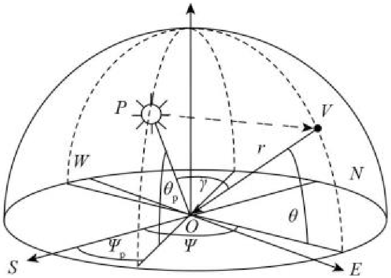
In order to use the polarized light field underwater for navigation, the variation law of the polarized light field in the sky should be determined first. The analytical relation between any space position V and sun position P in the horizon coordinate system is established, as shown in
Figure 1.
O is the observation origin,
θp is the solar altitude angle,
Ψp is the solar azimuth angle,
θ is the observed altitude angle,
Ψ is the observed azimuth angle, and
γ is the scattering angle in position V. The relation between the scattering angle and the observed position and the sun position satisfies the following equation [
24]:
The polarization azimuth
X represents the angle between the vibration direction of the E-vector of the incident sunlight at the observation point V and the meridian passing through the point [
24]:
The sky polarization azimuth at any geographic location is only related to the solar altitude angle, solar azimuth angle, observed altitude angle, and observed azimuth angle, and is not affected by other factors. Therefore, when the position of the sun is known at any time after the space position is determined, the polarization pattern of the sky at the location is stable, which provides a stable information source for the use of the polarized light field for navigation.
After determining the spatial longitude, latitude, and time, the solar azimuth angle Ψp and altitude angle θp can be queried through the solar calendar. The azimuth of the polarization or the direction of the solar meridian obtained by the polarization detection method can determine the reference angle between the carrier axis, which is the relative angle. The angle between the body axis and the true north can be obtained by means of compass-assisted orientation; namely, the course angle of the carrier.
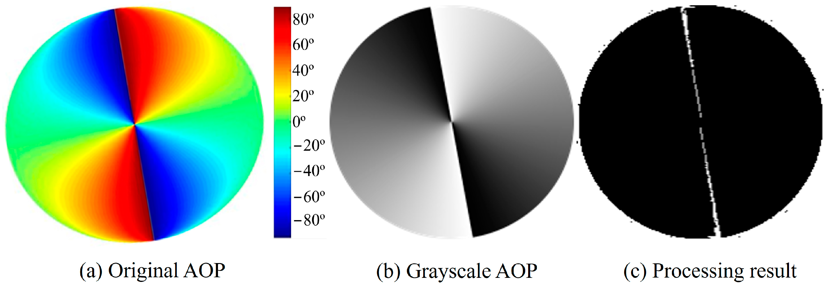
The polarization pattern is symmetrically distributed about the solar meridian. Different azimuth values of polarization can be distinguished by pixel values, and the direction can be distinguished. The feature region of the solar meridian has an obvious edge, which shows a significant mutation of the gray value in image processing. The extraction method of solar meridians is based on the Hough transform. Using the Stokes vector principle, the azimuth distribution mode of polarized light can be obtained by polarization camera and coordinate transformation. The azimuth of the solar meridian is extracted by the proposed method and the characteristic threshold is set to the characteristic region of the solar meridian. The edge of the characteristic region is detected by the operator and the linear direction of the edge is detected by the Hough transform (
Figure 2). The azimuth of the solar meridian is obtained by the symmetry distribution relationship. Next, we can calculate the course angle using the north finder data.
To estimate the deviation between the measured value and the true value, the theoretical value of the solar meridian azimuth is calculated by the astronomical calendar. The fixed error of the imaging test system is calculated and the measured value of each group of test samples is corrected. Suppose that the measured values of the solar meridian azimuth of each group of test samples are
x and the corresponding theoretical values are
y; then, the expression of the fixed error
F of the test system is:
n is the number of measured values in each set of test samples. The equation can be used to obtain the fixed error
F of the test system so as to correct the measured value of each group of test samples and obtain the absolute error value at different test moments.
According to research findings [
15,
16,
17], underwater polarization patterns, which contain abundant navigation information that humans can use, are similar to the atmospheric. Thus, we can realize underwater polarization navigation by modeling underwater polarization patterns and correcting the relevant navigation model. Next, we can construct an intelligent navigation method combining multi-source information (polarization and inertia) based on the polarization camera and inertial sensor to realize the underwater positioning.
4. Experiment and Results
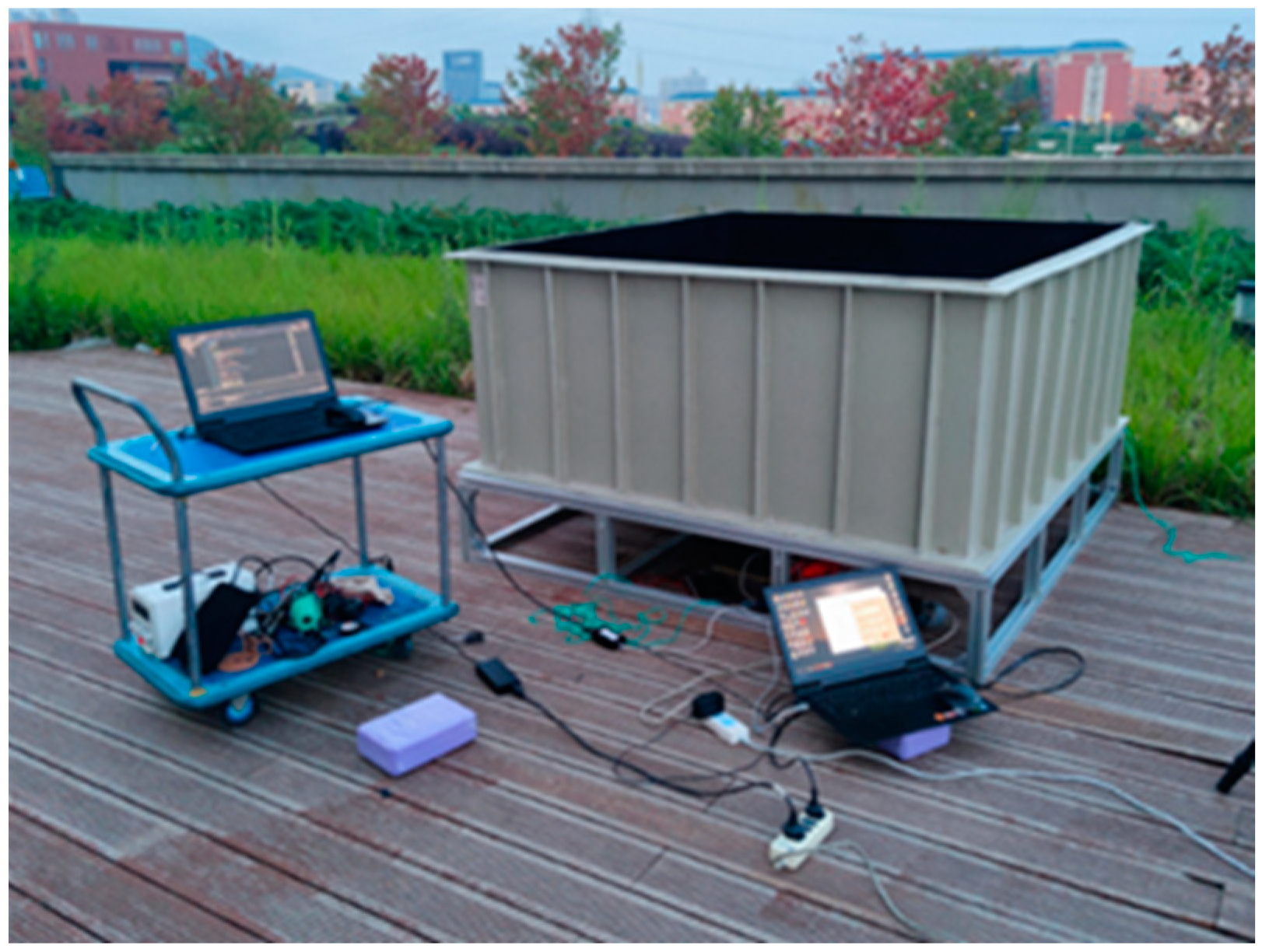
We first verified the course angle measurement of underwater polarization navigation (
Figure 3). The polarization camera was set up on the high-precision turntable, which was installed on the mounting plate with the north finder. The mounting plate was leveled by the level. A 2 m × 2 m × 1 m water tank filled with water was placed directly above the camera. There was an open observation window under the water tank, which was directly facing the camera detection position. During the test, the north finder first determined the initial direction of the datum axis measured by the polarization camera. Then, the upper computer sent instructions to control the step rotation of the precision turntable and recorded the course angle measured by the polarization camera. After several rotations of the turntable, the data collected by the camera were counted and the course angle accuracy was taken as the 2σ error fluctuation interval.
Table 1 is the results of angle measurement based on underwater polarization patterns when the solar meridian is at different angles. By comparing the measurement with the theory, we can obtain the mean error of the method, which is 0.30°. The measurement accuracy of the polarization azimuth is less than 0.69°. The results show that the underwater pattern of polarized light is closely related to the position of the sun, and the solar meridian is symmetrically distributed as the center line. The solar meridian can be used as the navigation reference line in the polarized light navigation method.
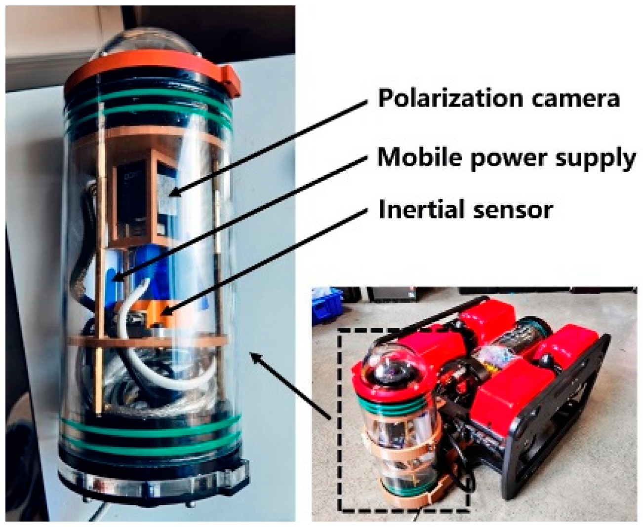
The accuracy of underwater polarization positioning was measured by the test platform of the ROV (
Figure 4). The ROV, which was connected to the upper computer, was equipped with a navigation system with a polarization camera and a high-precision inertial navigation module. The navigation system was used to measure the ROV position information, and the upper computer was used to control the ROV and receive navigation information. The surface unmanned ship was equipped with a high-precision satellite navigation module, which can steer a fixed trajectory by remote control and record satellite navigation data. At the ground station, the front camera of the ROV test platform was used to control the ROV to track the surface ship on the water surface.
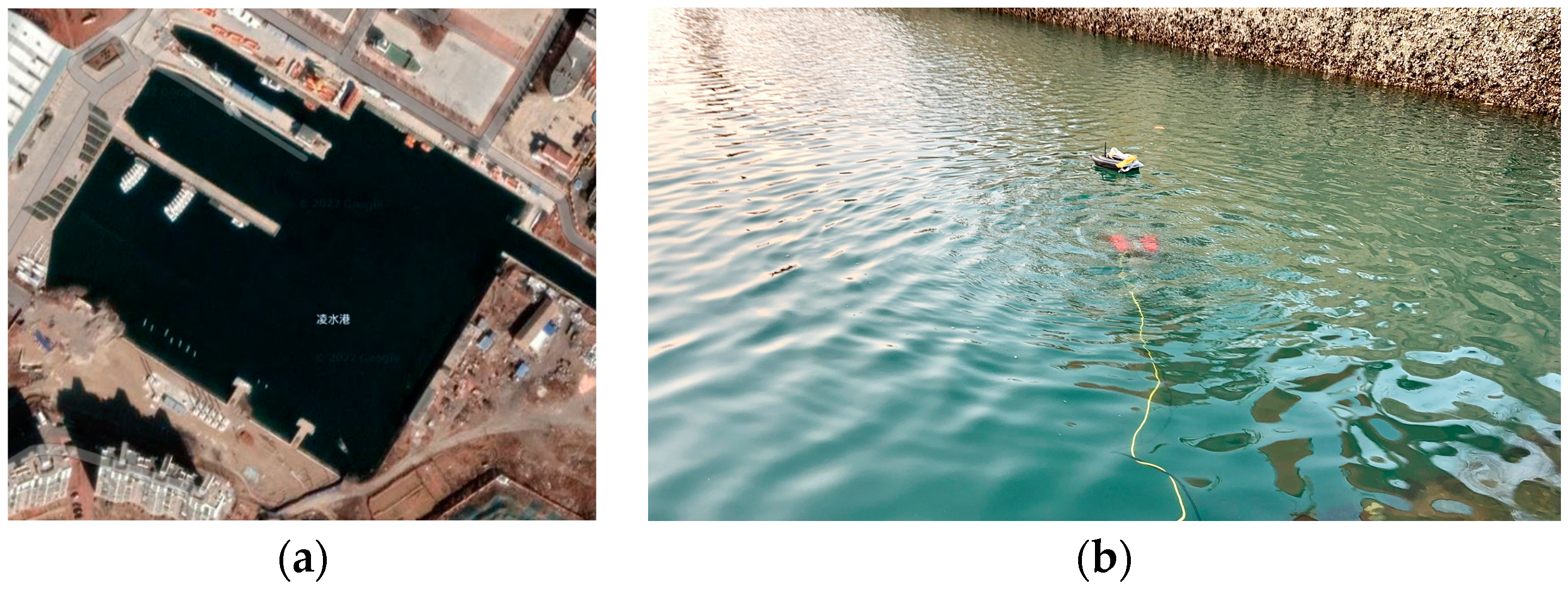
The experiment (
Figure 5) was conducted at 4 p.m. with a solar altitude angle of 15.27° and a solar azimuth of 71.03°. The weather was sunny but the water quality was poor. There was a breeze, causing waves on the water. The test site is close to the shore, which will produce a negative impact on the experiment.
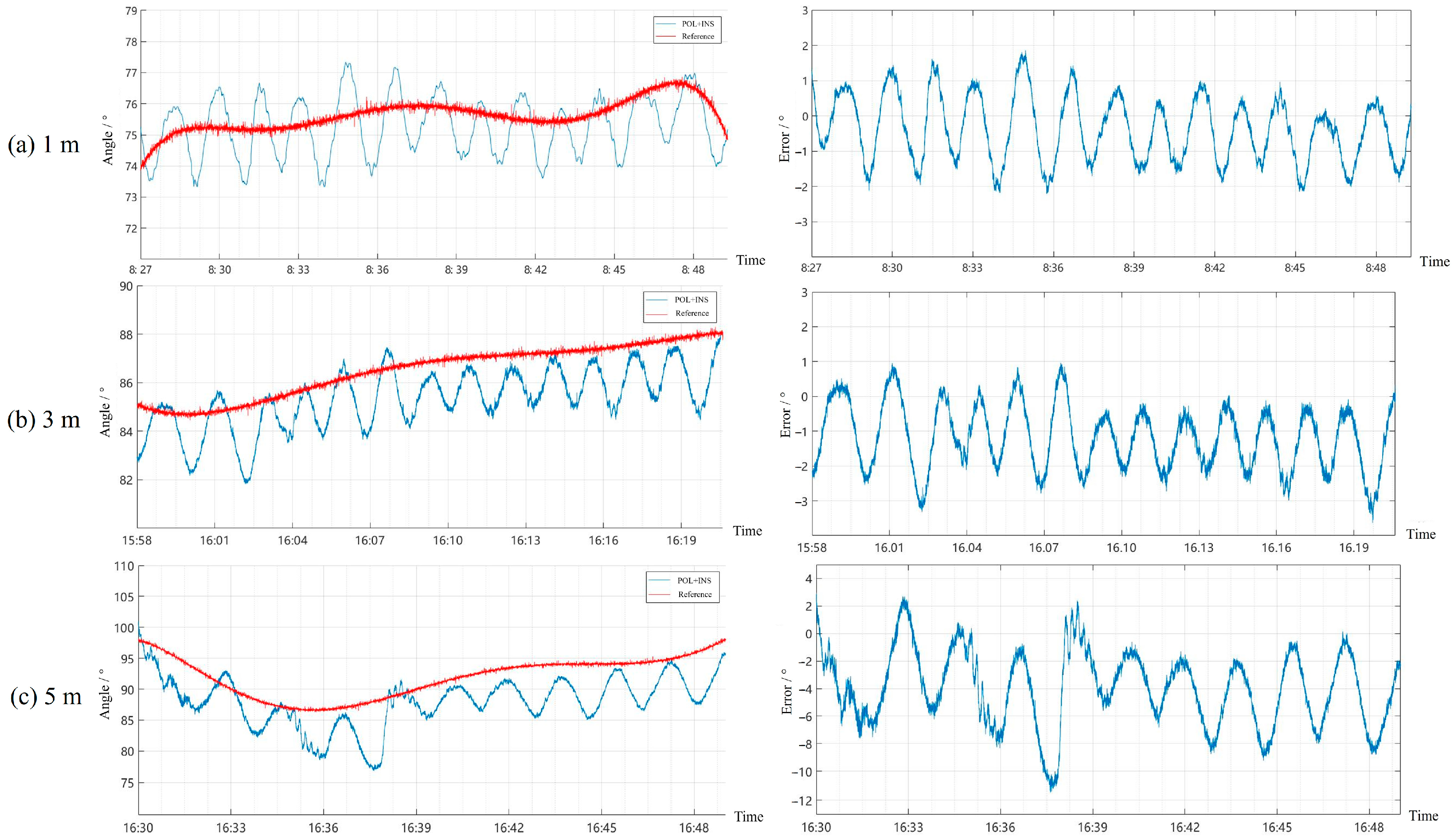
A variety of cruise routes and speeds were designed at different water depths. We then obtained the angle and position data measured by the polarization-based navigation system and further calculated related accuracy (
Figure 6). With the depth, the error increases gradually. As a new bionic visual navigation method, it cannot exactly work at much deeper depths. But as photoelectric detection devices improve and underwater image enhancement technology develops, polarization navigation will be able to work in deeper waters and play a more important role.
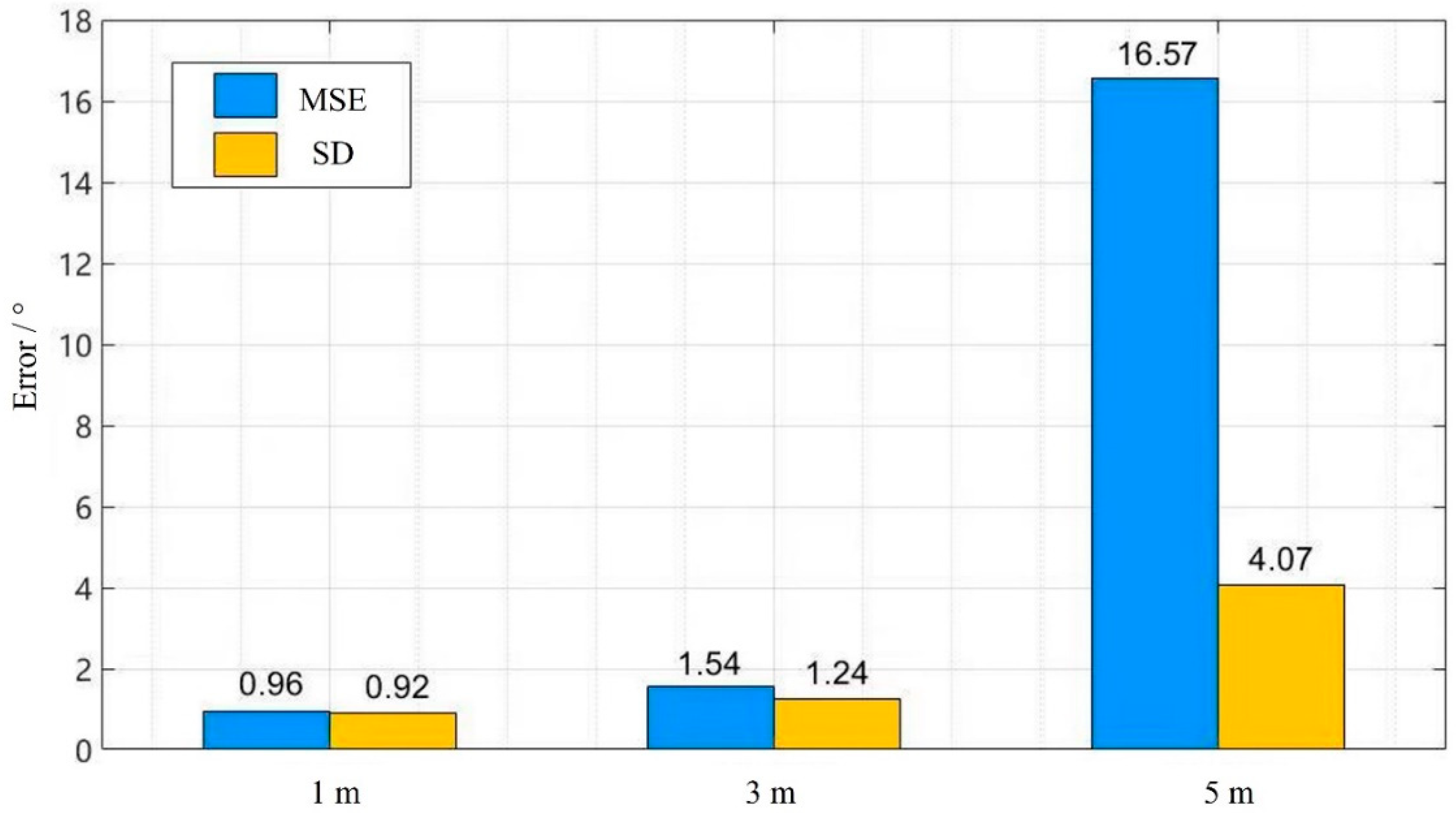
As shown in
Figure 7, the underwater polarization/inertia system will provide a smooth heading output for the vehicle. The MSE (Mean Square Error) and SD (Standard Deviation) of the angle error are 16.57° and 4.07° at a depth of 5 m, respectively. However, due to the multiple scattering caused by water depth, the model parameters are changed, and constant error is introduced.
Underwater navigation accuracy of traveling 100 m is better than 5 m within a depth of 5 m. The data using the fusion of polarized and inertial information have high robustness, good real-time performance, and no cumulative error accumulation. Outdoor experiments show that the polarization/inertial navigation system proposed by the paper had a high angle and positioning measurement accuracy.


