1. Introduction
Longitudinal vibration of the marine propulsion shafting system, which is under non-constant thrust excitation, arises with propeller propulsion technology, because the propeller operates in a stern flow field that is nonuniform in time and space. This nonuniformity derives from the asymmetry of the hull [
1]. In space, the nonuniformity generates a pulsating thrust of the blade and multi-blade frequency related to the propeller rotational speed, with continuous broadband excitation in time. With propellers still being the dominant propulsion technology, such longitudinal vibration problems are bound to exist. For marine vehicles, the longitudinal vibration of the propeller-shafting system is directly related to the radiated noise of the hull and becomes an essential target to improve the acoustic stealth [
2].
Severe longitudinal vibration problems in propulsion shafting systems first occurred in surface ships in the 1950s [
3]. The thin, hollow drive of the shaft makes it less rigid, causing the first-order critical rotational speed to fall within the shaft’s operating range, and the multiple propeller shafting system can mutually aggravate the stern flow distribution, increasing the excitation force. In the case of underwater vehicles, the complex conditions at different depths and seawater densities result in variations of the propeller thrust, making longitudinal vibration more troublesome and uncertain.
The key to clarifying the longitudinal vibration characteristics is to develop a suitable model of the shafting system. In tests on the longitudinal vibration of the shafting system of USS Simon Lake, Gary found that the gearbox, turbine, and compressor could be considered as a whole [
4]. Couchman simplified the shafting system to a single-degree-of-freedom system model, and proposed the calculation of equivalent mass and equivalent stiffness based on testing the first-order natural frequency of a Type V ship [
5]. Kelzon considered the shafting system as a continuous system, and simplified it as a uniform shaft model, with the propeller and thrust bearing as a concentrated mass and elastic boundary condition, respectively [
6]. Murawski found that there were torsional–longitudinal and bending–longitudinal coupled vibrations in the diesel engine shafting system. He emphasized the significance of boundary conditions, especially the accurate modeling of the thrust bearing [
7].
The above studies generally equated the propulsion shafting system with a non-rotating rod, not a rotor. A rotating shafting system has a lubricating oil film with the stiffness and damping properties [
8]. The wedge-shaped lubricating oil film between the thrust ring and thrust block in the thrust bearing affects the longitudinal vibration. By introducing the lubricant film into the shafting model, a relationship between shaft rotational speed and longitudinal vibration characteristics can be established.
The complexity and difficulty of longitudinal vibration problems in shafting systems arise from non-linear factors such as bearing lubrication, friction, and assembly clearances. The accuracy of the calculation depends on the refinement of the model and the reliabilities of the dynamic parameters. A more effective approach is to combine theory and experimentation.
Table 1 summarizes and compares the shafting system test rigs in the literature, which differ in composition and function according to the focus of the study. Pan [
9] and Wang [
10] utilized propellers in their shafting test rig. When the propeller speed was high, the water flow could not return in time and propeller idling occurred, resulting in unstable results. The effects of static thrust and rotational speed on the shafting system can be tested separately under the condition of a power source, but no corresponding tests were shown in [
11,
12]. In terms of the thrust bearing structure, Zhao innovatively utilized a hydraulic piston as the thrust block support structure, as opposed to the traditional balance block. This paper shows our second type of shafting system test rig.
This paper investigates the longitudinal vibration characteristics of the shafting system by combining experimental methods and theoretical analysis to ensure reliability and validity. We performed longitudinal vibration tests on our test rig with different combinations of static thrust and rotational speed. The accurate structural stiffness of the shafting system of our test rig was also tested. We model the shafting system of the test rig by the transfer matrix method, considering the static thrust device. The acceleration frequency response function of the thrust bearing is presented in this paper. To refine the model, we identify the remaining uncertain dynamic parameters using the Particle Swarm Optimization Algorithm. We aim to clarify how and why static thrust and longitudinal force transfer branches affect the longitudinal vibration of the shafting system, and we aim to identify the role and contribution of the thrust bearing in this. In addition, the data presented in this paper can provide subsequent researchers with ideas, data references, and even a direct reference for rig construction.
2. Test Rig
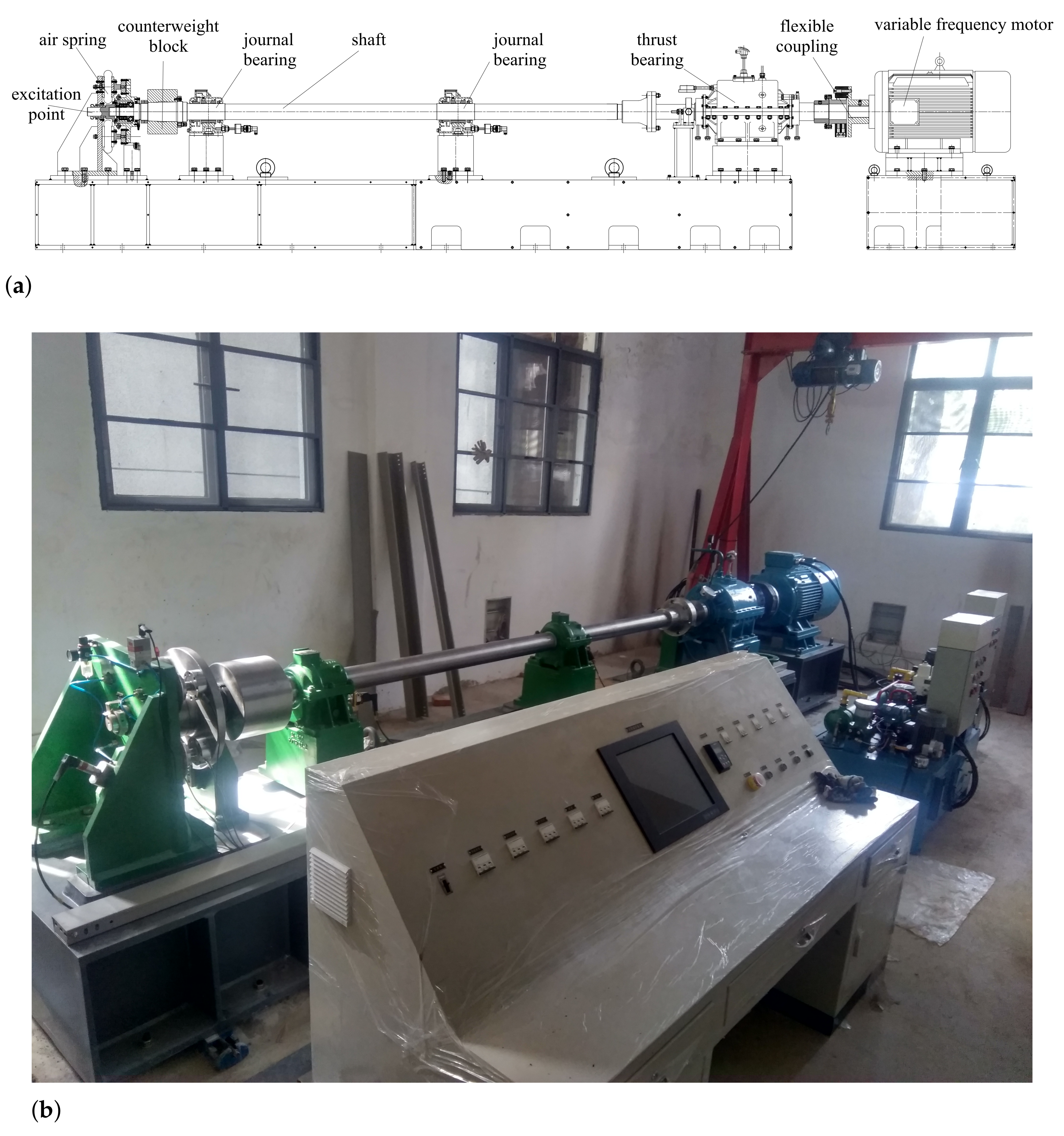
The shafting system test rig we built is shown in
Figure 1 and includes the air spring static thrust device, counterweight block, journal bearings, shaft, thrust bearing, flexible coupling, variable frequency motor, etc. To further reduce the disturbing effects of high-frequency vibration of the motor, it is mounted independently on one base, while the rest of the shafting system is mounted on another. An electrical console is designed, as well as a hydraulic lubrication system and an air system. The main technical parameters are:
A total length of shaft 5000 mm;
A basic diameter 105 mm;
A counterweight block mass 89.6 kg;
A maximum static thrust 55 kN.
The test rig simulates propeller propulsion using parallel static and dynamic forces. The air spring mounted on the stern provides static thrust, and its value can be adjusted by changing the airbag pressure. Dynamic forces were excited by force hammers, which also act on the stern end to simulate propeller excitation forces. To achieve the simultaneous transfer of static and dynamic forces to the rotating shaft, we designed a tapered ball bearing between the shaft and the air spring device to solve the connection problem between the rotating and the non-rotating shaft. Compared to using a propeller, the parallelism of static and dynamic forces allows the static thrust and rotational speed to be changed independently for the vibration test.
3. Vibration Tests on the Rig
3.1. Longitudinal Vibration Characteristics of Shafting
At the stern end, we use an excitation force hammer to apply an impulse excitation in the axial direction and arrange acceleration sensors on the thrust bearing housing and base to test the acceleration response. As the thrust bearing is the main transmission path for the longitudinal vibration of the shafting system, its acceleration response can reflect the amplitude of the secondary excitation force, which would be applied to the hull in practice.
Specifically, two acceleration sensors are arranged along the axis at the top of the upper housing of the thrust bearing, and the other two are arranged at the base of the thrust bearing, both symmetrically along the axis. The longitudinal vibration in the frequency range of 300 Hz is of interest. The sampling frequency is 1280 Hz, and the frequency resolution is 0.625 Hz. The acceleration frequency response of the thrust bearing was collected under different combinations of static thrusts and shaft rotational speeds.
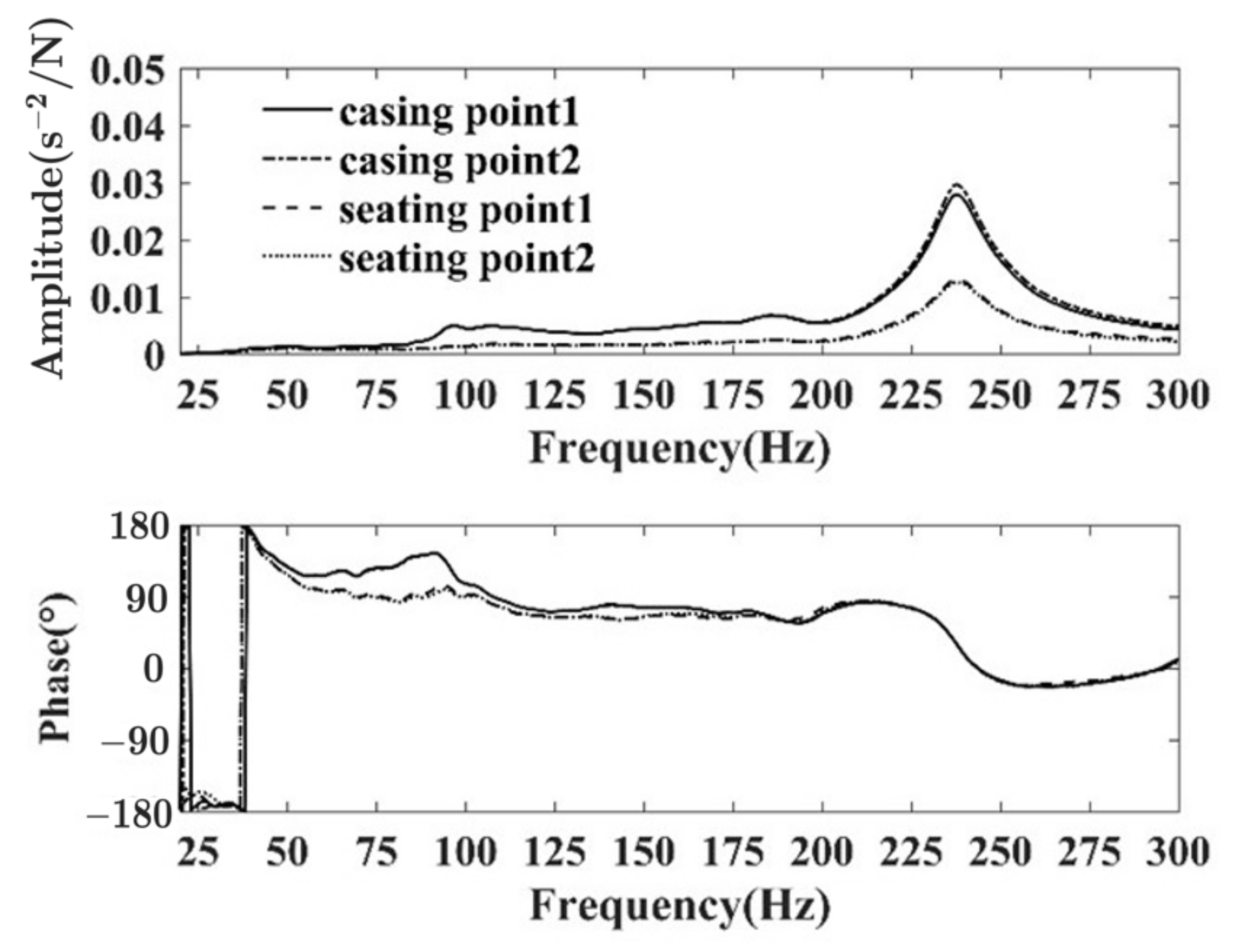
Figure 2 shows the acceleration frequency response curve of the thrust bearing tested at a static thrust of 30 kN and a shaft speed of 60 rpm. In
Figure 2, the casting points denote the two sensors at the top, and the seating points denote the two sensors at the base. It can be seen that the acceleration frequency responses of the two measurement points of the thrust bearing housing are consistent, indicating that the housing is vibrating as a whole, and a similar situation occurs in the base. The acceleration frequency response curves of the housing and base are similar, with only the peaks differing, indicating that the longitudinal vibration attenuates in the transmission channel of the thrust bearing structure. Except for those of the low frequencies, all phase angles are between 0°∼180°, indicating that only the first-order longitudinal vibration exists in the 300 Hz frequency range. Its corresponding natural frequency value is 237.5 Hz. There are several resonance peaks of lower amplitude on the housing’s acceleration frequency response curve, related to local resonances in the thrust bearing, which are discussed in
Section 5.
3.2. Comparison of Different Rotational Speeds
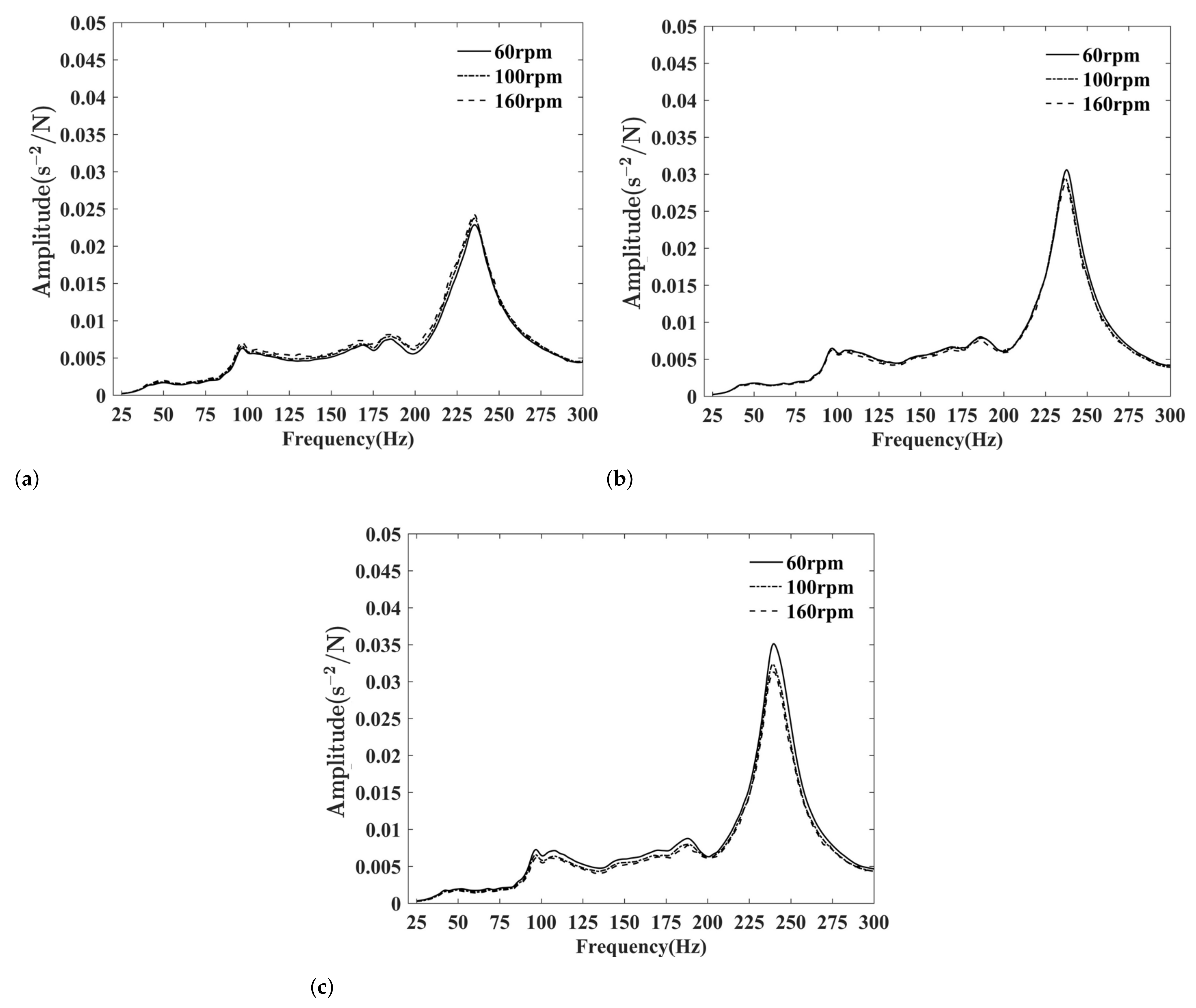
We repeated the longitudinal vibration test by varying the shaft rotational speed under the same static thrust. Without a loss of generality, the following discussion and analysis are based on the acceleration frequency responses of the base of the thrust bearing, because those of the thrust bearing housing and base are similar.
The results are shown in
Figure 3, and the curves in each subfigure are under the same static thrust while at different rotational speeds. The thrust bearing acceleration frequency response curves are consistent under each thrust, especially the resonance frequency, which indicates that the shaft rotational speed is not a major factor affecting vibration.
3.3. Comparison of Different Static Thrusts
We repeated the longitudinal vibration test by varying the static thrust at the same rotational speed. The results are shown in
Figure 4, including those when the shaft did not rotate. The resonance peak changes as the static thrust increases: the resonance peak amplitude and the corresponding frequency both increase. The increase in resonance peak amplitude derives from a reduction in shafting damping, which means that the greater the static thrust, the less damp. The increase in resonance frequency derives from a change in shafting system stiffness, which may originate from the lubricating oil film between the thrust ring and the thrust block, or the air spring static thrust device.
From
Figure 4d, the effect of the static thrust on the non-rotating shafting system is the same as that of the rotating one. As the thrust bearing has no lubricating oil film when the shaft is not rotating, it can be deduced that the increase in resonance frequency is related to the change in stiffness of the air spring static thrust device. Therefore, the static thrust affects the longitudinal vibration by varying the air spring stiffness. This property is similar if the test rigs use a static thrust device to simulate the propeller.
4. Test for Stiffness
Apart from the stern and thrust shafts, most of the other structures in the shafting system are assemblies and welded parts, such as thrust bearings. Therefore, it is difficult to calculate the stiffness accurately. Vassilopoulos has proposed a theoretical calculation method for thrust bearing stiffness [
16], where the stiffness of each component is first calculated based on material mechanics or contact theory, and then assembled to obtain the thrust bearing stiffness. As the stiffness of each element is obtained based on a simplified model and assumptions, the result is still an approximate solution. To provide accurate stiffness values for the vibration analysis, we directly tested the stiffness of the main structures, including the air spring static thrust device, the thrust bearing, and the base.
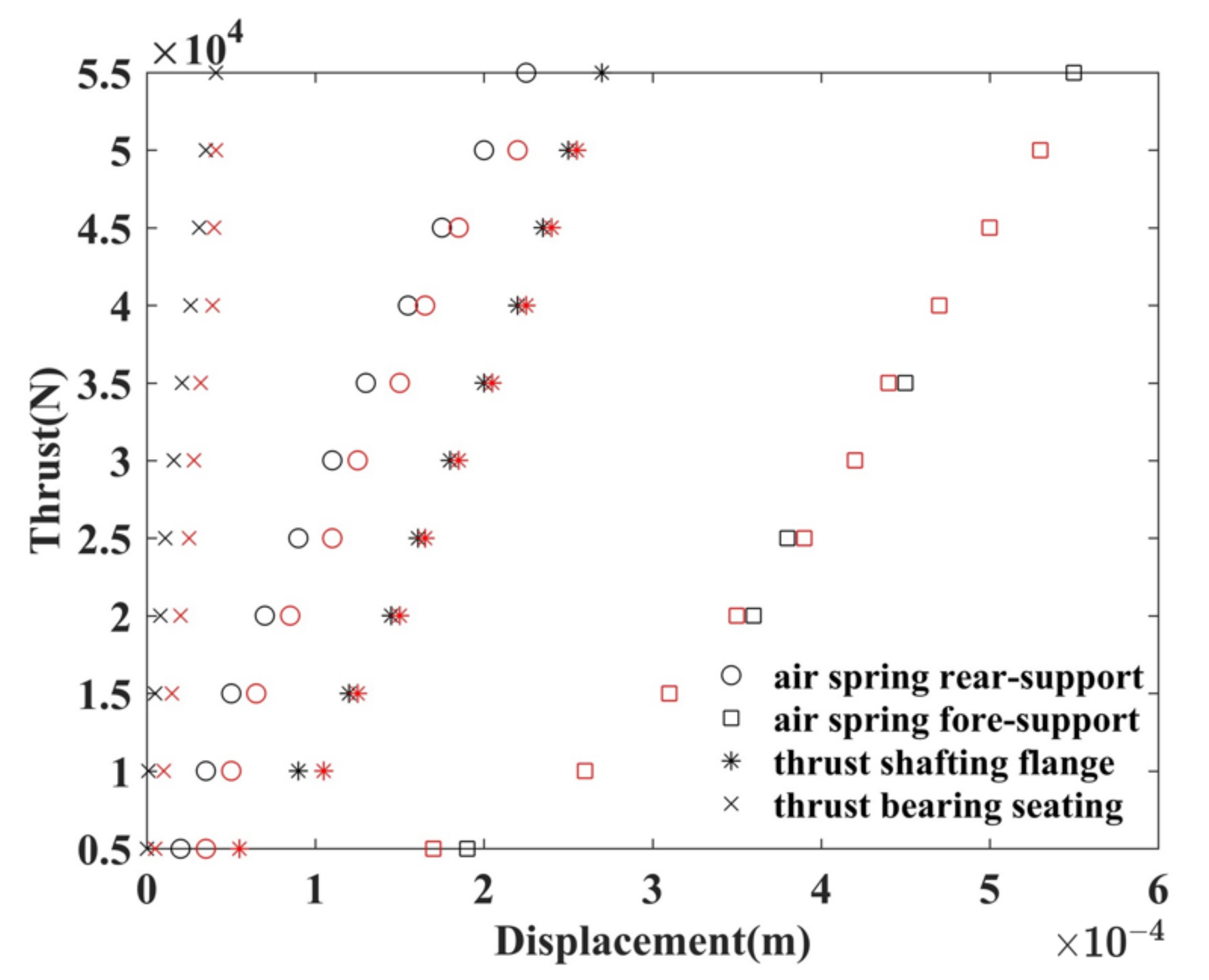
The static thrust force was applied to the stern end in certain load steps, and the displacement was measured at each step. We used 11 steps during the test. A percentage meter is located on the front and rear supports of the airbag, the thrust shaft flange, and the foot of the thrust bearing to measure the displacement values. The stiffness of the shafting system can be obtained at different speeds to analyze the variation of stiffness. To reduce random error interference, we repeated the process at the same speed to obtain an average value. We present the “static thrust-displacement” test data at 60 rpm in
Figure 5, as the results at different rotational speeds are consistent. In
Figure 5, the black points stand for loading and the red for unloading. It can be seen that the displacements during loading and unloading are not consistent, especially in the case of the airbag front bracket. The front bracket has a weaker stiffness than the rear and is the main direction of the airbag’s deformation.
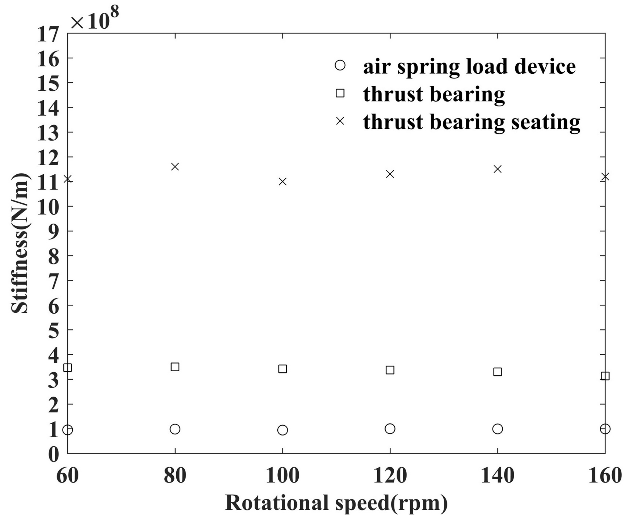
We performed least squares linear fitting on the “static thrust-displacement” data. The results at different rotational speeds are shown in
Figure 6, where the slopes of the fitted lines represent the stiffness values. It can be seen that the static thrust device, thrust bearing, and base stiffness are stable at different rotational speeds, 1.0 × 10
8 N/m, 3.4 × 10
8 N/m, and 1.1 × 10
9 N/m, respectively.
The least squares linear fitting process is shown as follows:
For a certain rotational speed, save the corresponding thrusts as the components of an 11 × 1 vector x and save the corresponding displacements as the components of an 11 × 1 vector y. Recall that we used 11 different thrust forces during our test.
Use four function bases , where and u is the independent variable of the function.
Calculate , where .
The normal equation can be expressed by
where
’s are the coefficients of the fitted function
,
is the
ith component of
x, and
is the
ith component of
y.
Let
denote the 11 × 4 matrix in (
1). According to the theory of the least squares linear fitting, we have
We obtain the fitted function of this certain rotational speed. Calculate the corresponding a’s of other rotational speeds.
The results show that ’s at every rotational speed, stating that the stiffnesses are in the elastic range. Therefore, we save the s as the corresponding stiffnesses.
We calculate the fluctuating values of different rotational speeds, comparing with the fitted stiffness of rotational speed 60 rpm. The results are present in
Table 2 and confirm our point clearly and directly, i.e., the static thrust device, thrust bearing, and base stiffness are stable at different rotational speeds. It can be seen that no fluctuating value exceeds 10%.
6. Discussion
To verify the previous inference that the stiffness of the airbag affects the resonant frequency, we varied the stiffness and calculated the corresponding acceleration frequency response of the thrust bearing, based on the identified dynamic parameters. The results are shown in
Figure 10. Unlike
Figure 4, the resonance peak in
Figure 10 decreases as the stiffness increases, because in the theoretical calculation only the stiffness changed, while the damping ratio of the shafting structure did not. In our vibration tests, they changed simultaneously when the static thrust was adjusted.
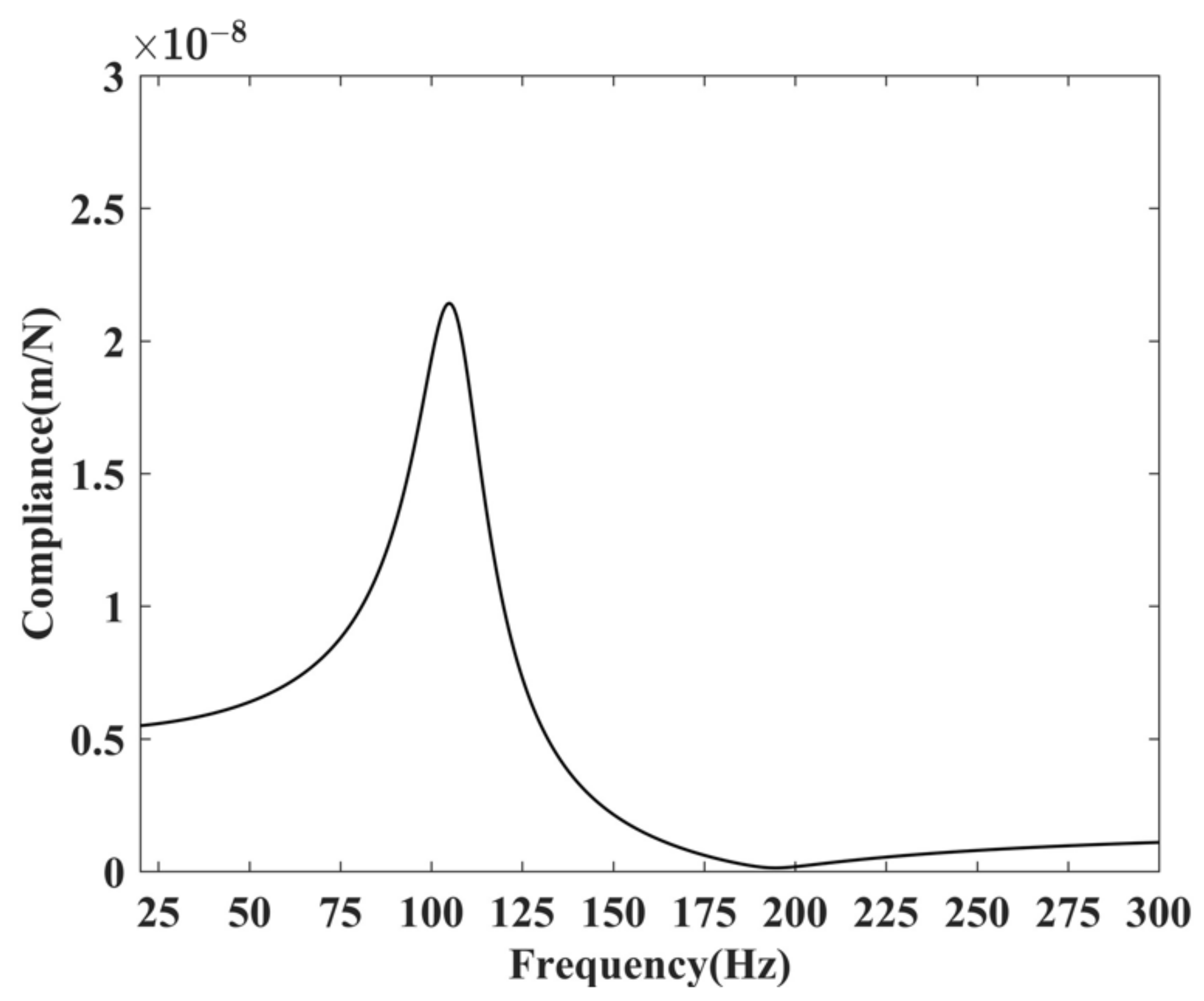
By substituting the identified parameters into Equation (
5), we have the dynamic flexibility curve shown in
Figure 11. The peak of the curve corresponds to the natural frequency of the thrust bearing, which is 103 Hz. According to the test results shown in
Figure 2, the frequency of the first local resonance peak is 98 Hz, which is closer to the natural frequency of the thrust bearing, indicating that it is generated by the resonance of the thrust bearing. The coupling between the thrust bearing and the shafting is weak at this time.
As mentioned previously, the thrust bearing and the fore shaft are two paths of longitudinal vibrations. The primary path can be identified by comparing the excitation forces transmitted. The hammer excitation data were collected for spectral analysis and, together with the identified parameters, substituted into the shafting model. We calculated the excitation forces transferred to the thrust bearing and front thrust shaft, respectively. The results of the transmissibility are shown in
Figure 12. The comparison shows that the thrust bearing is the main transmission channel for longitudinal shafting vibration. In addition, the force transmission characteristics show that the hammer excitation force is significantly amplified in the resonant state of the shafting system.
7. Conclusions
We designed a test rig to simulate the propulsion system of a ship. The rig simulates propeller propulsion in parallel with static and dynamic forces and allows the rotational speed and static thrust to be varied independently. Static and dynamic tests on the test rig were performed, and the dynamic parameters of the shafting system were identified by combining numerical models and the particle swarm optimization algorithm.
The test results and the theoretical analysis are consistent, proving the validity of both methods and the reliability of the results. Of the two variables, the longitudinal vibration is less affected by the shaft rotational speed, while the static thrust is the primary factor.
The static thrust device, as well as the thrust bearing, constitutes a branch of the shafting system, and its stiffness should be taken into account in the model. The branch effects reduce the original effective mass of the component. We obtain quantitative evidence to show that the thrust bearing is the main channel of the longitudinal vibration, and the excitation force via it is significantly amplified when the shafting resonates. As the additional transfer paths are unavoidable for any shafting system, our test data and analysis can provide a reference for subsequent researchers.


