Abstract
Swash motions are important for the design and assessment of beach protection projects, while the limitation of insightful observations in the swash zone still exists. An automatic identification method based on video imagery is developed to monitor and extract instantaneous swash motions in the laboratory. The method increases video sampling frequency and improves image enhancement in identification. The improved method fits well with the results of the manual method. The incident band roll-off of the swash spectrum in the experiment is consistent with those observed on natural beaches. Results have shown that on the barred beach, water depths influence the peak frequency in the incident band and cause a multi-peak swash spectrum. A large incident wave period causes a low peak frequency but high peak energy in the swash spectrum. Large incident wave height results in wider energy coupling, making swash to be saturated and more energy in swash energy. The existence of a barred beach promotes swash energy transferring from a high frequency to a low frequency.
1. Introduction
In the context of global climate change, extreme wave events such as tropical storms become more frequent and intensive (e.g., [1,2,3]). Wave runup during storm waves has always been a hot topic in coastal dynamic geomorphology and disaster prevention. Meanwhile, wave runup has been demonstrated as responsible for beach erosion, over-wash, and inundation [4,5,6,7,8].
Video systems are widely used in monitoring wave runup in the field. The imagery method is applied to acquire wave runup motions [9,10]. However, imagery method applications have several limitations in the laboratory. Firstly, low sampling frequency (usually lower than 30 Hz) and low identification accuracy in the laboratory influence the analysis of runup motions [11,12,13]. Low sampling frequency may cause the deficiency of runup motion information and introduce errors. Secondly, the usage of video imagery has several application differences in fields and laboratories, especially, edge detection of shoreline and runup. In runup motions captured, the white spray nearshore is defined as the propagating front of wave runup. In the usage of the imagery method, when using smooth material (e.g., concrete) to build a plane beach in laboratories, the difference is that runup motions on the concrete plane beach have low resolutions and low contrast. In summary, video imagery methods need to be developed and improved in the laboratory.
Wave runup is generated from potential energy which is transferred from the energy after wave dissipation [14], and typically can be separated into setup and swash. Swash is a time-varying phenomenon that has a variety of frequency components, usually larger than 0.003 Hz. Swash signatures are influenced by beach types. Field observations demonstrate that the infragravity band of swash spectra under different beach types have an obvious difference [15,16,17]. Swash signatures are discrepant under different water levels. Field observations suggest that wave energy dissipation during low tide is associated with maximum swash distribution [18,19]. Laboratory and field results indicate that different types of wave breaking also influence wave runup and swash distribution [7,15,16,20,21,22]. New evidence demonstrates that swash motions, related to reflection and breaking, force the long-wave [23,24,25,26,27]. However, most studies were focused on specific natural beaches based on a short-term wave runup dataset or low-resolution data. In the laboratory, parameters that influence the swash spectrum can be controlled.
The objective of this study is to utilize the improved imagery method in the swash experiments and investigate the spectra signature of swash motions. In the present work, Section 2 introduces the methodology, which includes experiment configuration, video measurements, and image improvements. Section 3 provides the results of the swash spectrum under the influence of incident wave height, water depth, and the beach profile. Section 4 discusses swash bispectrum and infragravity swash height proportion. Lastly, conclusions are given in Section 5.
2. Methodology
2.1. Experiment Configuration
The experiments were conducted in the wave flume located at the Key Laboratory of Ministry of Education for Coastal Disaster and Protection, Hohai University, China. The wave flume has a length of 50 m, a width of 0.5 m, and a height of 1.3 m. The flume is equipped with a hydraulic piston-type wavemaker and an absorbable wave-making mode that can help reduce the influence of secondary reflection waves. Wave absorbers are installed on the flume to mitigate wave reflection. The experimental setup is shown in Figure 1. The experiment’s beach profile contains two types using concrete: plane bed (Figure 1a) and barred bed (Figure 1b). The slope β of both profiles is 1/20. x = 0 is defined at the toe of the beach profile (z = 0). To magnify the effect of the beach profile, a barred beach is designed with steep seaward and shoreward slopes. The bar is located at x = 5.5 m with a seaward slope of 1/6, a shoreward slope of 1/2, a height of 0.4 m, and a triangular shape. The scale of the experimental model is 1:50.
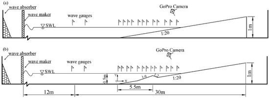
Figure 1.
Experimental configuration: The wave flume is equipped with a wavemaker and wave absorber. Wave gauges are fixed on the flume. (a) a plane bed. (b) a barred bed.
Water surface elevation is recorded by about 15 capacitance-type wave gauges with a sampling rate of 50 Hz installed on the flume. Before the experiment, wave gauges are calibrated. To record wave runup motions, a high-resolution camera with sampling rate 60 Hz is installed near the shoreline. A conventional lens is used by the camera and the resolution ratio is 2560 × 1440. In each case of the experiment, the still water level (SWL) is within the sight of the camera. Thus, each runup motion can be monitored and recorded. Under different water depths in the experiment, the locations of wave gauges and the camera are adjusted manually to fit the change of shoreline. The horizontal positions of instruments are listed in Table 1. In case T11, because of a larger change in water depth, the location of wave breaking changes a lot. Thus, the location and amount of wave gauges are adjusted.

Table 1.
Horizontal positions of instruments (unit: m). x = 0 is defined at the toe of the sloping bed.
Random waves defined by the JONSWAP spectrum were generated, with a peak enhancement factor of 3.3. The wave condition is determined by considering wave maker capacity and surf similarity parameter [28]. Surf similarity parameter can be expressed as:
where β is the bed slope, Hs0 is offshore wave height, and L0 is the offshore wavelength that is defined as using linear wave theory. Tm is the wave period, and g is the acceleration of gravity. The experiment condition is listed in Table 2. In the experiment, case T01 is set as the reference case. T01–T05 is listed to analyze the impact of incident wave height and wave period, by rising wave height from 0.08 m to 0.12 m and rising period from 1 s to 1.5 s. T00, T01, T06, and T11 are set to analyze the influence of water depth under plane beach. T0B and T11B are set to analyze the water depth influence under barred beach.

Table 2.
Experiment condition.
2.2. Video Measurements
The total methodology of image analysis is summarized as a flow diagram which can be divided into four parts (Figure 2): video calibration, image rectification, time-stack image, and time series analysis. The first two steps (video calibration and image rectification) can be summarized as video measurements.
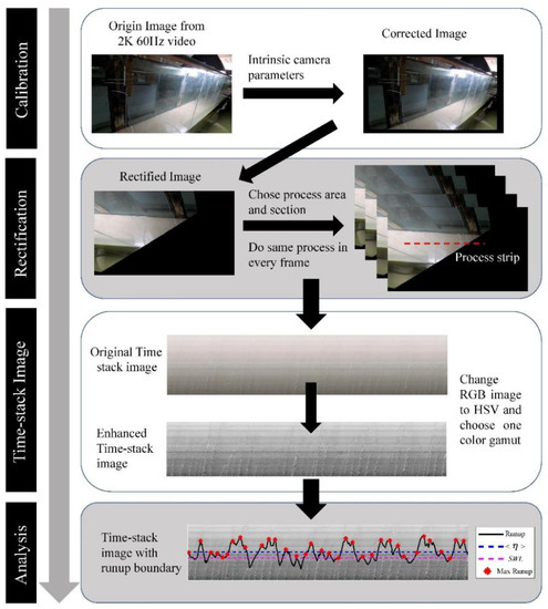
Figure 2.
Image process flow diagram in the experiment.
Video calibration is a process to eliminate camera distortion and obtain accurate swash motions. The calibration process is significant because the video monitoring system is built upon a non-metric camera. Four basic intrinsic camera parameters are determined in the calibration process: focal length (fc), principal point (cc), skew coefficient (αc), and distortions (kc). Those intrinsic parameters represent the parameter of the camera and remain constant during video monitoring. The calibration model used here is based on Heikkila and Silven [29], Bouguet [30]. After calibration, image error is lower than a pixel.
Image rectification is the process of establishing the relationship between image coordinates and geodetic coordinates in the world. The rectified images are plan view images that are free from the deformation and visual angle effect included by the camera. In the rectified images, one pixel represents a real distance in the geodetic coordinates.
Before image rectification, external parameters of the camera need to be identified based on several GCPs (geodetic control points) and intrinsic parameters. The geodetic coordinates of GCPs are the same as the relative coordinates which do not influence the final results of image rectification. The number of GCPs and the accuracy of GCPs’ coordinates are significant in the calculation of external parameters. At least six coordinates known as GCPs are necessary [31]. Usually, GCP coordinates are defined in the undistorted image. The undistorted image must be zoomed in when defining the accurate image coordinates of GCPs. GCPs can be selected on the fixed structure in the laboratory and must be visible in the image. In this work, GCPs are selected as the fixed points on the wave flume.
In this work, image rectification is done utilizing an MATLAB-based open-source software [32,33], which has already been successfully applied in several previous works of natural beach video monitoring [31].
2.3. Time-Stack and Image Improvement
Through video calibration and image rectification, all the monitoring videos are transformed into rectified images. Runup time series can be captured through the method of time-stack images and edge identification, using the rectified image [34,35]. A time-stack image is an image that combines both time and swash edge information, concentrating on one specific cross-section of the beach profile.
To get a time-stack image, the image strip and image area need to be determined in the rectified image. The image strip is the chosen cross-section of the beach profile while the image area is a temporary area of the rectified image to reduce the calculation load and noise. In the experiments, wave runup is observed to be uniform across the wave flume; therefore, the image strip is chosen at the center of the beach profile.
To get runup motions, edge identification on time-stack images is needed. The white spray is defined as the motion of wave runup and the set of maximum water levels evolution [34,36]. In common methods, low sampling rates are used in monitoring runup and swash motions. Sand is used as the material of beach profiles and the edges between beach and water are obvious to match [12,13,37]. When ignoring beach profiles’ change, beach profiles are made using concrete which introduces more difficulties to edge identification. Due to the similar colors and light disturbance, the edge between concrete bed and water is difficult to detect. Here, a developed method is presented. A higher camera sampling rate (60 Hz) is used to obtain more runup information. Two enhancement approaches are applied to reduce the influence of light and enhance the visuality of the time-stack image. The approaches include image sharpening and image equalization.
The effect of enhancement approaches is visualized in Figure 3. In Figure 3a, time-stack images are ordinary gray images and are difficult to detect the edge of runup motions. After image equalization (Figure 3b), the swash motions are more obvious to be detected in the time-stack image. In Figure 3b, edge identification has misidentified the edge of runup motions without image sharpening, while well-identified under image sharpening.
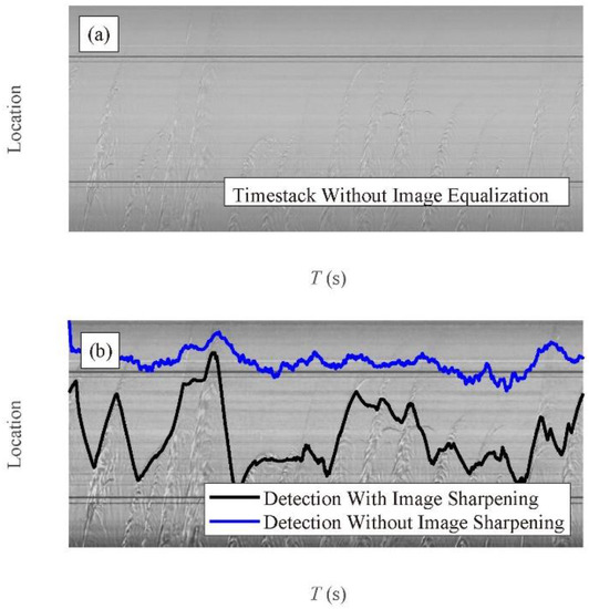
Figure 3.
An example application of image sharpening and image equalization. (a) Time-stack image without image equalization. (b) Edge identification comparison between with and without image sharpening, using the time-stack image under image equalization.
Time series of wave runup are obtained after edge identification on time-stack images. Swash can be expressed as [36]:
where R is the wave runup height, S is the swash height, and <η> is the swash set-up.
Figure 4a shows an example of time-stack image with wave runup edge (black solid line), wave set-up (blue solid line), SWL (carmine dotted line), and maximum runup (red star marker) using the method described above. Figure 4b is a comparison between the probability distribution of individual runup height and the Gaussian distribution. Figure 4c indicates an example of image errors during processing compared with manual detection. In the present work, image errors are always lower than a pixel (0.02 cm) after calibrating camera distortion.
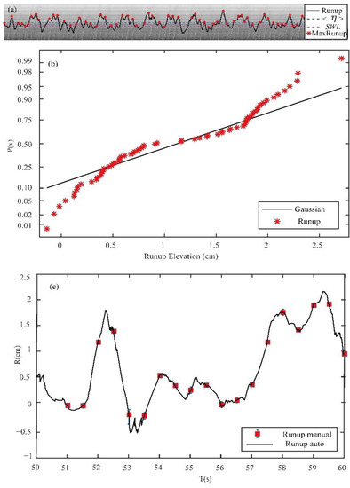
Figure 4.
Example of time-stack image: (a) time-stack image with runup edge (black solid line), wave set-up (blue dotted line), SWL (carmine dotted line), and max runup (red star marker); (b) probability cumulative distribution of individual wave runup (red points) and Gaussian distribution (black solid line); (c) automatic wave runup time series compared with a manual process.
3. Results
Using the imagery methods, the time series of swash motions under different wave and water conditions were obtained. In this part, swash time series are used to analyze and study the effect of water depth, wave conditions, and beach profiles on the swash spectrum.
3.1. Nearshore Wave Spectrum and Swash Spectrum
The spectrum of wave and swash motions is obtained using Welch’s method and Hamming’s window. In the wave spectrum, the chosen frequency of separating the short-wave and the long-wave is 0.5/fp [38].
On the plane beach (Figure 5a), the results demonstrate that the wave spectrum has a peak in the short-wave band before breaking (WG09) while the short-wave energy dissipates and the long-wave energy increases in the nearshore (WG14). Meanwhile, the swash spectrum and the infragravity band of wave spectrum (WG14) have the same tendency for energy evolution. Wave energy at WG14 is larger in the short-wave band (>0.5/fp) than swash energy, indicating that most energy in the short-wave band is dissipated, while the energy in the long-wave band increases. In the infragravity band, energy has a slight increase in the 0.05 Hz–0.5/fp frequency band, which represents some energy transformed from the short-wave band to the long-wave band, while in Figure 5b, a similar phenomenon can be observed. The difference is that wave spectrum still has energy growth from WG14 to the swash spectrum. This is related to the difference in relative water depth of WG14. In Figure 5b, the location of WG14 has a longer distance from the shoreline; thus, wave energy still evolves after WG14.
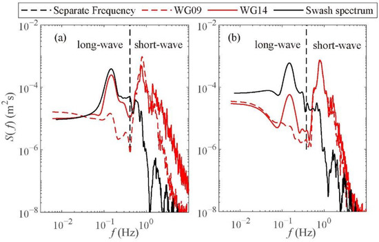
Figure 5.
(a) Wave spectrum evolution of experiment case T00 under the water depth of 0.42 m. (b) Wave spectrum evolution of experiment case T01 under the water depth of 0.45 m. The black dash line is the separation frequency of short-wave and long-wave. WG09 (red dash line) is located before wave breaking and WG14 (red solid line) is located nearshore.
On the barred beach, the wave spectrum is similar to the plane beach before breaking. However, the wave spectrum is different after breaking (Figure 6). Energy connections between wave and swash are more complex. With the same incident wave condition, wave energy is nearly the same on two profiles before breaking. The short-wave dissipates more energy and the long-wave band gets more energy on the barred beach. When the frequency is lower than 0.7 Hz, the swash spectrum has a multimodal peak on the barred beach and PSD (Power Spectrum Density) energy is slightly larger when the frequency is lower than 0.05 Hz. The main reason for wave and swash energy evolution on different beaches is the different wave-breaking types that cause the difference in energy transformation.
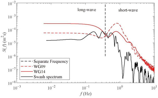
Figure 6.
Wave spectrum evolution of experiment case T00B. The black dash line is the separation frequency of short wave and long wave. WG09 (red dash line) is located before wave breaking and WG14 (red solid line) is located nearshore.
3.2. Effects of Water Depth on Swash Spectrum
Swash is divided into two frequency bands: incident band (f > 0.05 Hz) and infragravity band (f < 0.05 Hz) [15,39,40]. The incident swash band includes sea swells while the infragravity band includes standing waves and edge waves. The incident swash band roll-off is the slope of the saturated region which varies between −3 and −4 [15] and it is influenced by the measurement, beach slope, and porosity [41,42]. The incident band roll-off is shown in Figure 6, Figure 7, Figure 8, Figure 9 and Figure 10, which has a good agreement with field observations.
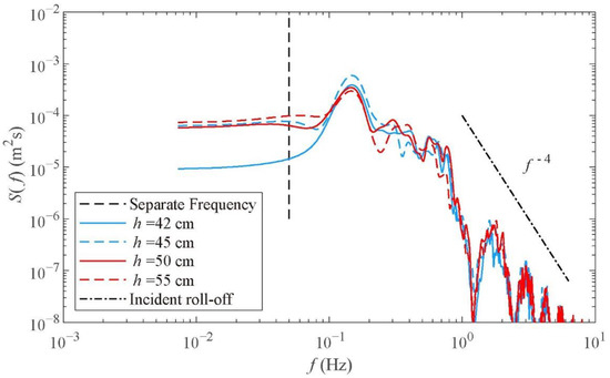
Figure 7.
Swash spectrum evolution with the same wave condition and different experimental water depths on the plane beach (T00, T01, T06, T11). The black dash line is the separation frequency of the incident swash band and infragravity swash band.
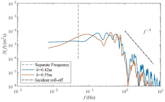
Figure 8.
Swash spectrum evolution with the same wave condition and different experimental water depths on the barred beach (T0B and T11B). The black dash line is the separation frequency of the incident swash band and infragravity swash band.
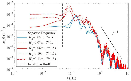
Figure 9.
Swash spectrum evolution with the same experimental water depth and different water conditions (T01, T02, T03, T04, T05). Black dash line is the separation frequency of incident swash band and infragravity swash band.
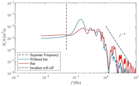
Figure 10.
Swash spectrum with the same wave condition and different experiment profiles (T00, T0B). The black dash line is the separation frequency of the incident swash band and infragravity swash band.
With the same wave condition (Figure 7), it is shown that the swash spectrum has the same peak frequency in the incident band under different water depths. The energy at peak frequency nearly remains the same. In the shallow water depth (h = 42 cm), results indicate that swash energy has a decrease in the infragravity band compared with other experimental water depths. The reasons are discussed in detail in Section 4.1. A slight increase in the infragravity band is shown with the increase in water depths (Figure 7). On the barred beach, water depths have a significant impact on the spread of swash frequency (Figure 8). In the incident swash band, it is shown that peak frequency increases with the enlargement of water depth. Peak energy remains the same under different depth conditions. The infragravity band of swash is influenced by water depths while energy decreases with the depths.
In summary, water depths in the plane beach experiments nearly have no obvious effect on the incident band of the swash spectrum. While in the barred beach experiments, water depths influence the peak frequency in the incident band and cause a multi-peak spectrum. Infragravity swash energy decreases under higher water depths. All the differences are based on the difference in wave breaking.
3.3. Effects of Incident Wave Condition on Swash Spectrum
To analyze wave condition effects on the swash spectrum, incident wave periods and heights are considered. With the same beach profile and water depth in the experiments (Figure 9), peak frequency varies under different incident wave periods. With a large incident wave period, the swash spectrum has a minor peak frequency but large peak energy in the incident band. The incident wave period does not affect the roll-off of the incident swash band (f−4).
Incident wave heights have a great impact on the swash spectrum. When the incident wave period (Tm) is 1 s, a slight increase of infragravity and incident band energy (blue solid and blue dashed line) is observed in the swash spectrum, under the increase of incident wave height. This is resulting from the saturation of the swash zone. More details are discussed in Section 4.1 using the methods of bispectrum. With a larger wave period (Tm = 1.5 s), swash spectrum energy is unsaturated obviously. Swash energy increases with the incident wave height in a frequency lower than 0.5 Hz. The increase in the infragravity swash band is much larger than the increase in the incident band. Meanwhile, the increased rate of swash energy becomes lower with the increase of wave height, which suggests that swash energy becomes saturated.
3.4. Effect of the Beach Profile on Swash Spectrum
Swash spectra on the plane beach and barred beach are compared under the same experiment condition (Figure 10). On barred beach swash, the roll-off f−4 seems inappropriate (red solid line). Combined with Figure 8, the incident swash roll-off is affected by beach profiles. In the plane beach experiments, roll-off is f−4, while on the barred beach, roll-off is f−3 which is similar to a dissipative beach.
On the barred beach, the swash spectrum has multi-peaks that are in low peak energy. Under the same wave condition, more total swash energy can be calculated on the plane beach in Figure 10. More energy dissipated in the surf zone on the barred beach results in less energy in the swash spectrum. The maximum peak frequency on the barred beach is larger than the peak on the plane beach. In the infragravity swash band, energy on the barred beach is larger than the plane beach and nearly remains the same. More energy exists in the band larger than 1 Hz on the barred beach.
4. Discussion
4.1. Swash Bispectral Analysis
Bispectral analysis is widely used in the analysis of energy transfer between different frequencies in swash, nonlinear waves, and infragravity waves [43,44,45]. Bispectral analysis provides more evidence on energy response and transformation in the swash zone. Bryan and Coco [35] suggested that the interesting pattern of swash bispectrum lies in the band (f/2, f/2). The wavelet-based bispectrum used here is based on van Milligen et al. [46]. The bispectrum measures the phase coupling between three wavelet components of frequency. Bicoherence is the normalized bispectrum and is a measure of the amount of phase coupling between two signals or in a signal (Figure 11). The value of bicoherence ranges from 0 to 1, representing the degree of wave phase coupling and denoting a maximal coupling [46]. The imagery part of the bispectrum is used to determine the direction of swash energy transformation (Figure 12). Color intensity is the magnitude of energy transfer and also denotes the energy transformation direction. Positive values of the imagery part indicate energy transfer from f1, f2 to f3 (f3 = f1 + f2) while negative values represent the opposite.
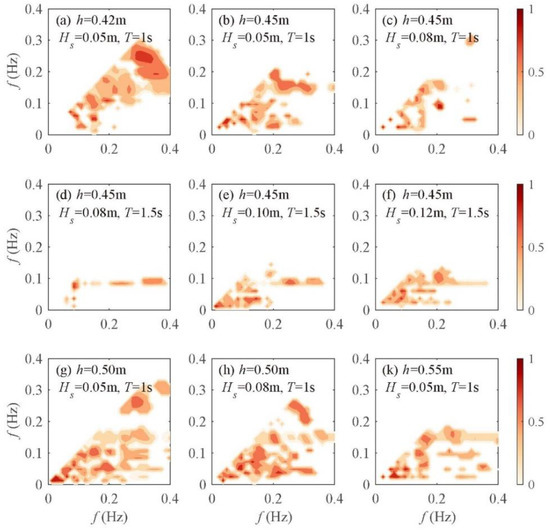
Figure 11.
Swash bicoherence of different experiment conditions: (a) T00, (b) T01, (c) T02, (d) T03, (e) T04, (f) T05, (g) T06, (h) T07, (k) T11. Xlabel and Ylabel are wave components frequency. Colorbar denotes the degree of swash bicoherence.
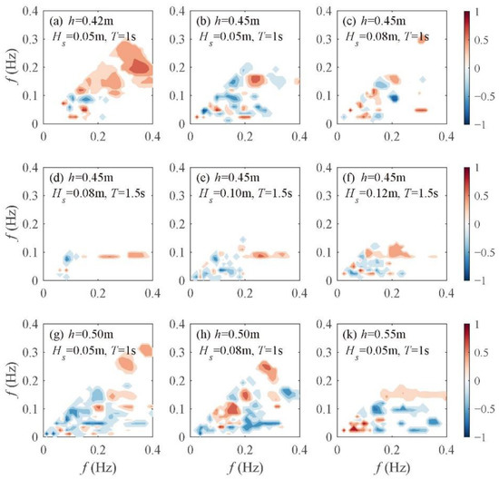
Figure 12.
Imagery part of Swash bispectrum of different experiment conditions: (a) T00, (b) T01, (c) T02, (d) T03, (e) T04, (f) T05, (g) T06, (h) T07, (k) T11. Xlabel and Ylabel are wave components frequency. Colorbar denotes the imagery part of swash bispectrum value.
Bispectral analysis provides more details on the effects of water depth. Bicoherence results are used to find out whether swash exchanges energy between two energy bands (Figure 11). With the same wave condition (Figure 11a,b,g,k), a max value b(0.1, 0.03) exists, indicating an energy connection between infragravity and an incident band under different water depths in the experiments. With the increase of water depth, the frequency coupling in the bicoherence becomes lower. The degree of energy exchange in the imagery part is similar to the results of bicoherence (Figure 12). Incident swash energy mainly transfers to a higher frequency when the frequency is larger than 0.2 Hz (Figure 12a,b,g,k). Under the shallow water depth (h = 42 cm), a more obvious coupling band can be found in the bicoherence. An energy connection within the incident swash band is also observed in Figure 11a. In an interesting pattern, frequencies of 0.04 Hz and 0.1 Hz have an energy input from 0.14 Hz, which is mainly found in shallow water depths (Figure 12a). Under larger water depths, the direction of energy transformation is low frequency to high frequency (Figure 12b,g,h). Therefore, the shallow water depth (h = 42 cm) results in the infragravity band decrease in Figure 7.
Effects of wave conditions can also be enriched using bispectral analysis. With the same incident water depth and period (Tm = 1 s), when increasing incident wave height, swash bicoherence seems not to change much in the frequency (f1) lower than 0.2 Hz (Figure 11b,c). Although bicoherence is almost the same in low frequency, the imagery part is different (Figure 12b,c). When increasing wave height, a wider energy coupling band exists near (0.1, 0.04) and transfers energy to a higher frequency. This may also be related to swash saturation and can explain swash spectra in Figure 9 (blue line). Under a high incident wave period (Tm = 1.5 s) and the same water depth in the experiments (h = 0.45 m), the band (0.03–0.1 Hz, 0.03–0.05 Hz) has a strong energy exchange and mainly transfers to a higher frequency (Figure 11d–f). Near (0.1 Hz, 0.05 Hz), the direction of energy transformation is contrary, from f3 to f1 and f2 (Figure 12d–f). Therefore, with a higher incident wave period, the energy of swash spectrum increases with the incident wave height (red line in Figure 9) and is less easy to be saturated. Furthermore, when the incident wave height increases, swash bicoherence shows a more wide frequency coupling near the frequency of (0.1, 0.03) Hz. This leads to the infragravity swash band energy growing faster than the incident band in Figure 9.
Bicoherence and the imagery parts of the bispectrum on the barred beach are shown in Figure 13. Compared with those on the plane beach (Figure 11a and Figure 12a), the band range of energy exchange is much larger on the barred beach plane in both bispectra. In Figure 13a, an energy connection is observed during (0.03–0.2, 0.03) Hz. The connection band is divided into two parts according to Figure 13b. The first part transfers energy to a higher frequency, resulting in the peak frequency (almost 0.18 Hz) in Figure 10 while the other transfers to a lower frequency. More energy transfers from the incident swash band to the infragravity swash band (Figure 13b), which leads to the energy of the infragravity swash band being larger on the barred beach in Figure 10.
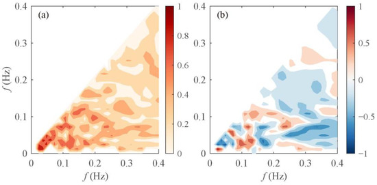
Figure 13.
Swash bispectrum of the barred beach (T00B): (a) Swash bicoherence, (b) imagery part of swash bispectrum.
4.2. Infragravity Swash Height Proportion
Swash height is defined as the difference between the maximum upwash and the minimum downwash in a complete swash cycle. Significant swash height is the integration of different swash bands and is calculated as follows [36,47]:
where Sinc is the incident significant swash height, Sig is the infragravity significant swash height, and PSD (f) is the power spectrum density of the swash spectrum.
The infragravity band has been demonstrated to contribute to the total swash height under varying beach slopes. A possible relationship between the surf similarity parameter and significant swash height ratio of the two bands is visualized (Figure 14). Figure 14 shows that in the same wave condition (ξ = 0.279 and 0.221, dissipative), the ratio of infragravity and the incident band swash height increase with the increasing experimental water depth. The increase of experimental water depth leads to more energy in the infragravity band, just the same as the results shown in Figure 7. Meanwhile, with the same water depth in the experiments (same marker in Figure 14), the proportion of swash height Sig/Sinc first increases and then decreases with increasing surf similarity. The increasing trend of Sig/Sinc demonstrates that the ratio of incident and infragravity swash energy on the reflective beach is greatly lower than those on the dissipative beach.
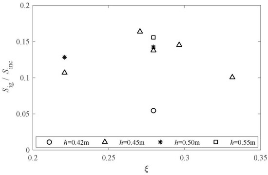
Figure 14.
Relationship between surf similarity and the ratio of significant infragravity swash and significant incident swash.
5. Conclusions
Laboratory experiments of swash oscillations based on video imagery are presented for a plane beach and a barred beach with varying wave conditions and water depths. Based on the limitations of sampling rates and edge identification in common methods, an improved imagery method is presented. The sampling frequency of runup monitoring is increased to obtain more swash information and edge enhancement approaches (image sharpening and image equalization) are applied to obtain accurate swash motions. Through all the improvements, the runup and swash motions are obtained and transferred into time series which have an error within a pixel (0.02 cm). The automatic data is in good agreement with the manual data and have the same roll-off in the swash spectrum compared with field observations. Spectra signatures of swash are analyzed under the effect of water depth, wave condition, and beach profile. The bispectrum and infragravity swash height proportions are discussed to obtain more details to confirm the results of the spectra.
Results show that the long-wave band of the wave spectrum is similar to the swash spectra, inferring an energy connection between wave and swash. Wave breaking types contribute to the swash spectrum. Restricted to experimental conditions, it needs to be explored in future works, as well as the influence of reflection.
In the plane beach experiments, water depth does not affect the swash spectrum in the incident swash band, but the proportion of infragravity swash height increases with water depth. On the barred beach experiment, water depth influences the swash frequency spread and the total swash energy remains the same. Peak frequency increases with the experimental water depth and the peak energy remains the same.
A large incident wave period has a lower peak frequency but a larger peak energy in the swash spectrum. The swash spectrum is easy to be saturated under a low incident wave period (Tm = 1 s). Bispectral analysis confirms this. Swash bicoherence seems to remain the same when the frequency is lower than 0.2 Hz under a low period which is related to swash saturation. Wave height influences peak energy, total swash, and wider energy coupling between two swash bands in bicoherence.
On the barred beach, swash energy is lower in the incident swash band and larger in the infragravity band compared with the plane beach. The bispectrum results indicate that more energy is transferred from the incident swash band to the infragravity swash band. A multimodal peak frequency is demonstrated in swash spectra on the barred beach and wider energy exchange.
Author Contributions
Conceptualization, C.Z. and J.S.; methodology, H.Y. and J.S.; software, H.Y. and C.Z.; validation, J.S., X.C. and H.Y.; formal analysis, H.Y.; investigation, H.Y.; resources, C.Z.; data curation, H.Y. and X.C.; writing—original draft preparation, H.Y.; writing—review and editing, C.Z., J.S. and Y.L.; visualization, H.Y.; supervision, C.Z. and J.S.; project administration, J.S.; funding acquisition, C.Z. and J.S. All authors have read and agreed to the published version of the manuscript.
Funding
This research was funded by the Key Program of National Natural Science Foundation of China, grant number 41930538, the Guangxi Key Laboratory of Beibu Gulf Marine Resources, Environment and Sustainable Development, grant number MRESD-2022-B03, the National Natural Science Foundation of China, grant number 51879096, and the National Science Foundation of China, grant number 52201317.
Institutional Review Board Statement
Not applicable.
Informed Consent Statement
Not applicable.
Data Availability Statement
Not applicable.
Acknowledgments
We thank three anonymous reviewers for their constructive comments that significantly improved the quality of this paper. Our students Wenshan Wan and Lipeng Zhang are acknowledged for their contributions in conducting laboratory experiments.
Conflicts of Interest
The authors declare no conflict of interest.
References
- Vitousek, S.; Barnard, P.L.; Fletcher, C.H.; Frazer, N.; Erikson, L.; Storlazzi, C.D. Doubling of coastal flooding frequency within decades due to sea-level rise. Sci. Rep. 2017, 7, 1399. [Google Scholar] [CrossRef] [PubMed]
- Vousdoukas, M.I.; Mentaschi, L.; Voukouvalas, E.; Verlaan, M.; Jevrejeva, S.; Jackson, L.P.; Feyen, L. Global probabilistic projections of extreme sea levels show intensification of coastal flood hazard. Nat. Commun. 2018, 9, 2360. [Google Scholar] [CrossRef] [PubMed]
- Shi, J.; Zheng, J.; Zhang, C.; Joly, A.; Zhang, W.; Xu, P.; Sui, T.; Chen, T. A 39-year high resolution wave hindcast for the Chinese coast: Model validation and wave climate analysis. Ocean Eng. 2019, 183, 224–235. [Google Scholar] [CrossRef]
- Guza, R.T.; Thornton, E.B. Swash oscillations on a natural beach. J. Geophys. Res. 1982, 87, 483–491. [Google Scholar] [CrossRef]
- Blenkinsopp, C.E.; Matias, A.; Howe, D.; Castelle, B.; Marieu, V.; Turner, I.L. Wave runup and overwash on a prototype-scale sand barrier. Coast. Eng. 2016, 113, 88–103. [Google Scholar] [CrossRef]
- Gomes da Silva, P.; Dalinghaus, C.; González, M.; Gutiérrez, O.; Espejo, A.; Abascal, A.J.; Klein, A.H. Estimating flooding level through the Brazilian coast using reanalysis data. J. Coast. Res. 2016, 75, 1092–1096. [Google Scholar] [CrossRef]
- Zhang, C.; Li, Y.; Cai, Y.; Shi, J.; Zheng, J.; Cai, F.; Qi, H. Parameterization of nearshore wave breaker index. Coast. Eng. 2021, 168, 103914. [Google Scholar] [CrossRef]
- Li, Y.; Zhang, C.; Chen, D.; Zheng, J.; Sun, J.; Wang, P. Barred beach profile equilibrium investigated with a process-based numerical model. Cont. Shelf Res. 2021, 222, 104432. [Google Scholar] [CrossRef]
- Vousdoukas, M.I.; Velegrakis, A.F.; Dimou, K.; Zervakis, V.; Conley, D.C. Wave run-up observations in microtidal, sediment-starved pocket beaches of the Eastern Mediterranean. J. Mar. Syst. 2009, 78, S37–S47. [Google Scholar] [CrossRef]
- Almar, R.; Blenkinsopp, C.; Almeida, L.P.; Cienfuegos, R.; Catalán, P.A. Wave runup video motion detection using the Radon Transform. Coast. Eng. 2017, 130, 46–51. [Google Scholar] [CrossRef]
- Shankar, N.; Jayaratne, M. Wave run-up and overtopping on smooth and rough slopes of coastal structures. Ocean Eng. 2003, 30, 221–238. [Google Scholar] [CrossRef]
- Palmsten, M.L.; Holman, R.A. Laboratory investigation of dune erosion using stereo video. Coast. Eng. 2012, 60, 123–135. [Google Scholar] [CrossRef]
- Blenkinsopp, C.E.; Bayle, P.M.; Conley, D.C.; Masselink, G.; Gulson, E.; Kelly, I.; Almar, R.; Turner, I.L.; Baldock, T.E.; Beuzen, T.; et al. High-resolution, large-scale laboratory measurements of a sandy beach and dynamic cobble berm revetment. Sci. Data 2021, 8, 1–11. [Google Scholar]
- Hunt, I.A., Jr. Design of sea-walls and breakwaters. Trans. Am. Soc. Civ. Eng. 1959, 126, 542–570. [Google Scholar] [CrossRef]
- Ruessink, B.G.; Kleinhans, M.G.; van den Beukel, P.G.L. Observations of swash under highly dissipative conditions. J. Geophys. Res. Ocean. 1998, 103, 3111–3118. [Google Scholar] [CrossRef]
- Ruggiero, P.; Holman, R.A.; Beach, R.A. Wave run-up on a high-energy dissipative beach. J. Geophys. Res. 2004, 109. [Google Scholar] [CrossRef]
- Hughes, M.G.; Aagaard, T.; Baldock, T.E.; Power, H.E. Spectral signatures for swash on reflective, intermediate and dissipative beaches. Mar. Geol. 2014, 355, 88–97. [Google Scholar] [CrossRef]
- Guedes, R.M.C.; Bryan, K.R.; Coco, G.; Holman, R.A. The effects of tides on swash statistics on an intermediate beach. J. Geophys. Res. 2011, 116. [Google Scholar] [CrossRef]
- Guedes, R.M.C.; Bryan, K.R.; Coco, G. Observations of wave energy fluxes and swash motions on a low-sloping, dissipative beach. J. Geophys. Res. Ocean. 2013, 118, 3651–3669. [Google Scholar] [CrossRef]
- Zhang, C.; Zhang, Q.; Zheng, J.; Demirbilek, Z. Parameterization of nearshore wave front slope. Coast. Eng. 2017, 127, 80–87. [Google Scholar] [CrossRef]
- Shi, J.; Shi, F.; Zheng, J.; Zhang, C.; Malej, M.; Wu, G. Interplay between grid resolution and pressure decimation in non-hydrostatic modeling of internal waves. Ocean Eng. 2019, 186, 106110. [Google Scholar] [CrossRef]
- Zheng, J.; Yao, Y.; Chen, S.; Chen, S.; Zhang, Q. Laboratory study on wave-induced setup and wave-driven current in a 2DH reef-lagoon-channel system. Coast. Eng. 2020, 162, 103772. [Google Scholar] [CrossRef]
- Martins, K.; Blenkinsopp, C.E.; Almar, R.; Zang, J. The influence of swash-based reflection on surf zone hydrodynamics: A wave-by-wave approach. Coast. Eng. 2017, 122, 27–43. [Google Scholar] [CrossRef]
- Gao, J.; Ma, X.; Dong, G.; Chen, H.; Liu, Q.; Zang, J. Investigation on the effects of Bragg reflection on harbor oscillations. Coast. Eng. 2021, 170, 103977. [Google Scholar] [CrossRef]
- Gao, J.; Ma, X.; Zang, J.; Dong, G.; Ma, X.; Zhu, Y.; Zhou, L. Numerical investigation of harbor oscillations induced by focused transient wave groups. Coast. Eng. 2020, 158, 103670. [Google Scholar] [CrossRef]
- De Moura, T.G.R. Infragravity Wave Forcing in the Surf and Swash Zone; The University of Queensland: St. Lucia, QLD, Australia, 2016. [Google Scholar]
- Moura, T.; Baldock, T.E. New Evidence of Breakpoint Forced Long Waves: Laboratory, Numerical, and Field Observations. J. Geophys. Res. Ocean. 2018, 123, 2716–2730. [Google Scholar] [CrossRef]
- Battjes, J.A. Surf Similarity. Coast. Eng. 1975, 1974, 466–480. [Google Scholar]
- Heikkila, J.; Silven, O. A four-step camera calibration procedure with implicit image correction. In Proceedings of the IEEE Computer Society Conference on Computer Vision and Pattern Recognition, San Juan, PR, USA, 17–19 June 1997; pp. 1106–1112. [Google Scholar]
- Bouguet, J. Camera Calibration Toolbox for Matlab (1.0); CaltechDATA: Pasadena, CA, USA, 2022. [Google Scholar] [CrossRef]
- Andriolo, U. Nearshore Hydrodynamics and Morphology Derived from Video Imagery. PhD Thesis, Universidade de Lisboa, Lisbon, Portugal, 2018. [Google Scholar]
- Wolf, P.R.; Dewitt, B.A.; Wilkinson, B.E. Elements of Photogrammetry with Applications in GIS; McGraw-Hill Education: New York, NY, USA, 2014. [Google Scholar]
- Taborda, R.; Silva, A. COSMOS: A lightweight coastal video monitoring system. Comput. Geosci. 2012, 49, 248–255. [Google Scholar] [CrossRef]
- Bailey, D.G.; Shand, R.D. Determining wave run-up using automated video analysis. Proc. Second. New Zealand Conf. Image Vis. Comput. 1994, 2, 2.11.1–2.11.8. [Google Scholar]
- Vousdoukas, M.I.; Kirupakaramoorthy, T.; Oumeraci, H.; de la Torre, M.; Wübbold, F.; Wagner, B.; Schimmels, S. The role of combined laser scanning and video techniques in monitoring wave-by-wave swash zone processes. Coast. Eng. 2014, 83, 150–165. [Google Scholar] [CrossRef]
- Stockdon, H.F.; Holman, R.A.; Howd, P.A.; Sallenger, A.H. Empirical parameterization of setup, swash, and runup. Coast. Eng. 2006, 53, 573–588. [Google Scholar] [CrossRef]
- Erikson, L.H.; Hanson, H. A method to extract wave tank data using video imagery and its comparison to conventional data collection techniques. Comput. Geosci. 2005, 31, 371–384. [Google Scholar] [CrossRef]
- Janssen, T.T.; Battjes, J.A. Long waves induced by short-wave groups over a sloping bottom. J. Geophys. Res. 2003, 108, 3252. [Google Scholar] [CrossRef]
- Cox, N.; Dunkin, L.M.; Irish, J.L. An empirical model for infragravity swash on barred beaches. Coast. Eng. 2013, 81, 44–50. [Google Scholar] [CrossRef]
- Gomes da Silva, P.; Coco, G.; Garnier, R.; Klein, A.H.F. On the prediction of runup, setup and swash on beaches. Earth-Sci. Rev. 2020, 204, 103148. [Google Scholar] [CrossRef]
- Thornton, E.B.; Guza, R. Energy saturation and phase speeds measured on a natural beach. J. Geophys. Res. Oceans 1982, 87, 9499–9508. [Google Scholar] [CrossRef]
- Guza, R.T.; Thornton, E.B.; Holman, R.A. Swash on Steep and Shallow Beaches. Coast. Eng. Proc. 1985, 1984, 708–723. [Google Scholar]
- Bryan, K.R.; Coco, G. Observations of nonlinear runup patterns on plane and rhythmic beach morphology. J. Geophys. Res. 2010, 115. [Google Scholar] [CrossRef]
- Dong, G.; Chen, H.; Ma, Y. Parameterization of nonlinear shallow water waves over sloping bottoms. Coast. Eng. 2014, 94, 23–32. [Google Scholar] [CrossRef]
- Bertin, X.; de Bakker, A.; van Dongeren, A.; Coco, G.; André, G.; Ardhuin, F.; Bonneton, P.; Bouchette, F.; Castelle, B.; Crawford, W.C. Infragravity waves: From driving mechanisms to impacts. Earth-Sci. Rev. 2018, 177, 774–799. [Google Scholar] [CrossRef]
- Van Milligen, B.P.; Sánchez, E.; Estrada, T.; Hidalgo, C.; Brañas, B.; Carreras, B.; García, L. Wavelet bicoherence: A new turbulence analysis tool. Phys. Plasmas 1995, 2, 3017–3032. [Google Scholar] [CrossRef]
- Almar, R.; Blenkinsopp, C.; Almeida, L.P.; Catalán, P.A.; Bergsma, E.; Cienfuegos, R.; Viet, N.T. A new remote predictor of wave reflection based on runup asymmetry. Estuar. Coast. Shelf Sci. 2019, 217, 1–8. [Google Scholar] [CrossRef]
Publisher’s Note: MDPI stays neutral with regard to jurisdictional claims in published maps and institutional affiliations. |
© 2022 by the authors. Licensee MDPI, Basel, Switzerland. This article is an open access article distributed under the terms and conditions of the Creative Commons Attribution (CC BY) license (https://creativecommons.org/licenses/by/4.0/).