Virtual Inertia-Based Inverters for Mitigating Frequency Instability in Grid-Connected Renewable Energy System: A Review


Abstract
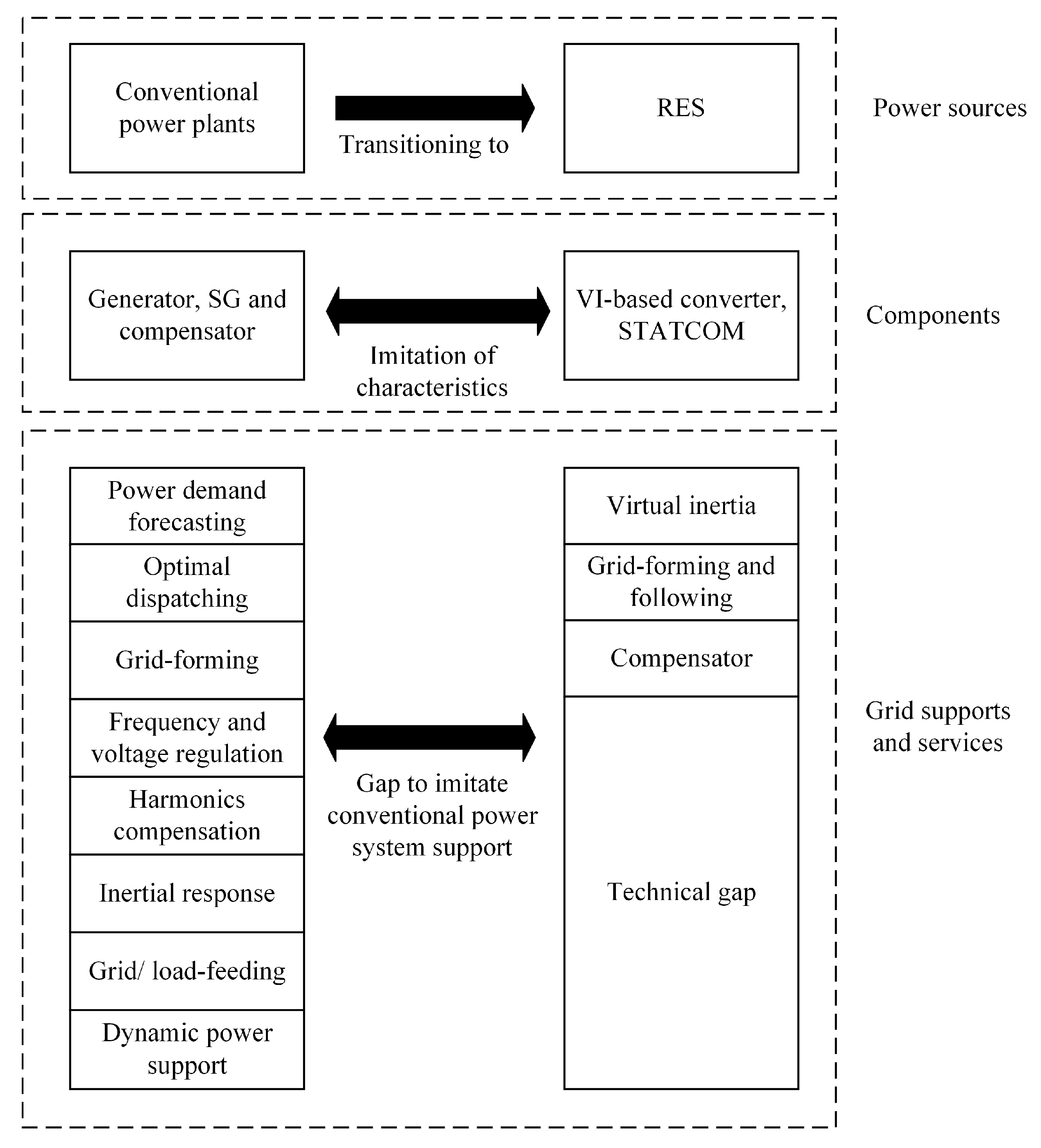
1. Introduction
- RES exhibits low or non-existent inertial responses which lead to frequency instability [8].
- In the event of a fault and sudden load change, the system frequency deviates from the nominal frequency [9].
- The frequency nadir and rate of change of frequency (RoCoF) are expected to be higher in the event of a fault or sudden load change, which activates the load-shedding controller to trip frequency relay [10].
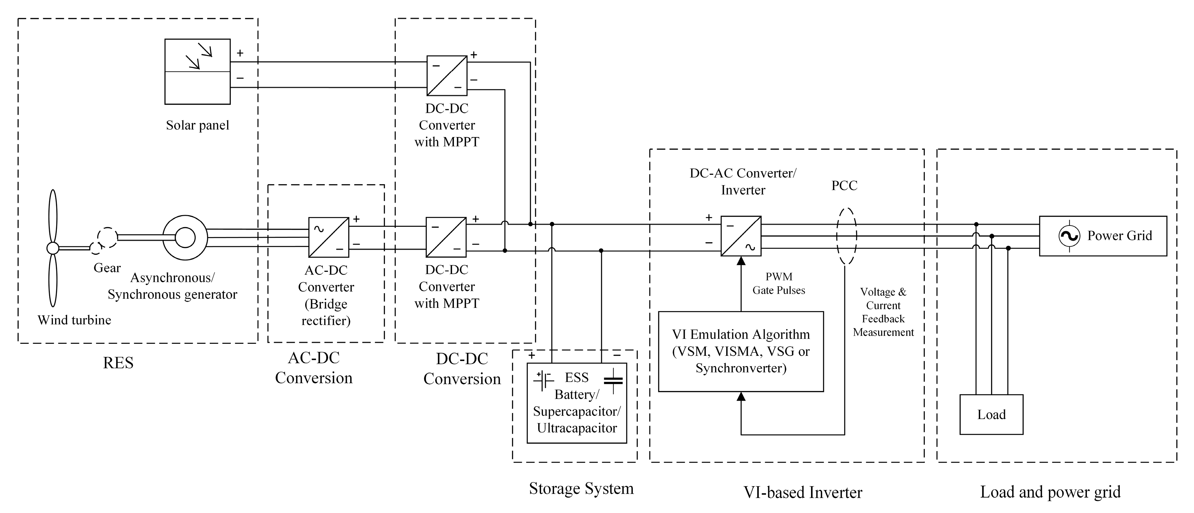
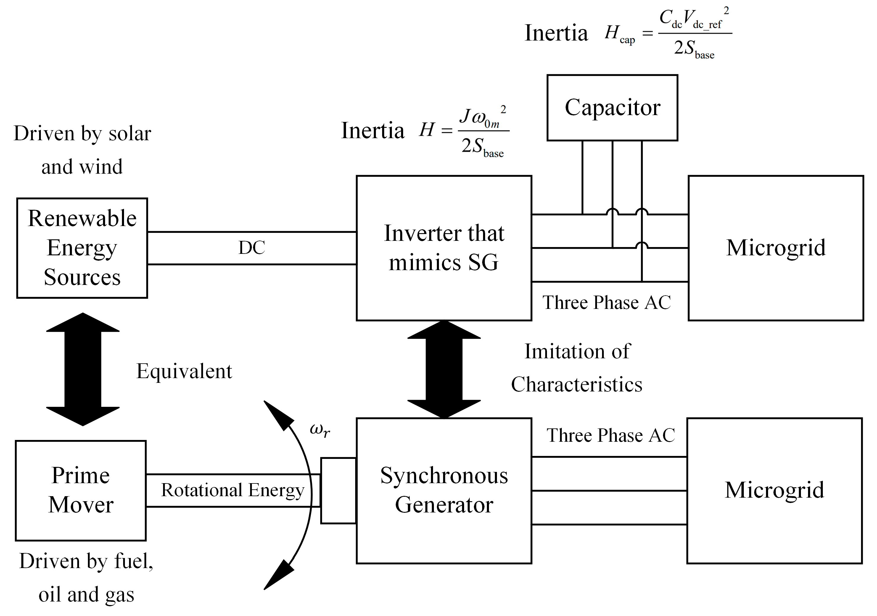
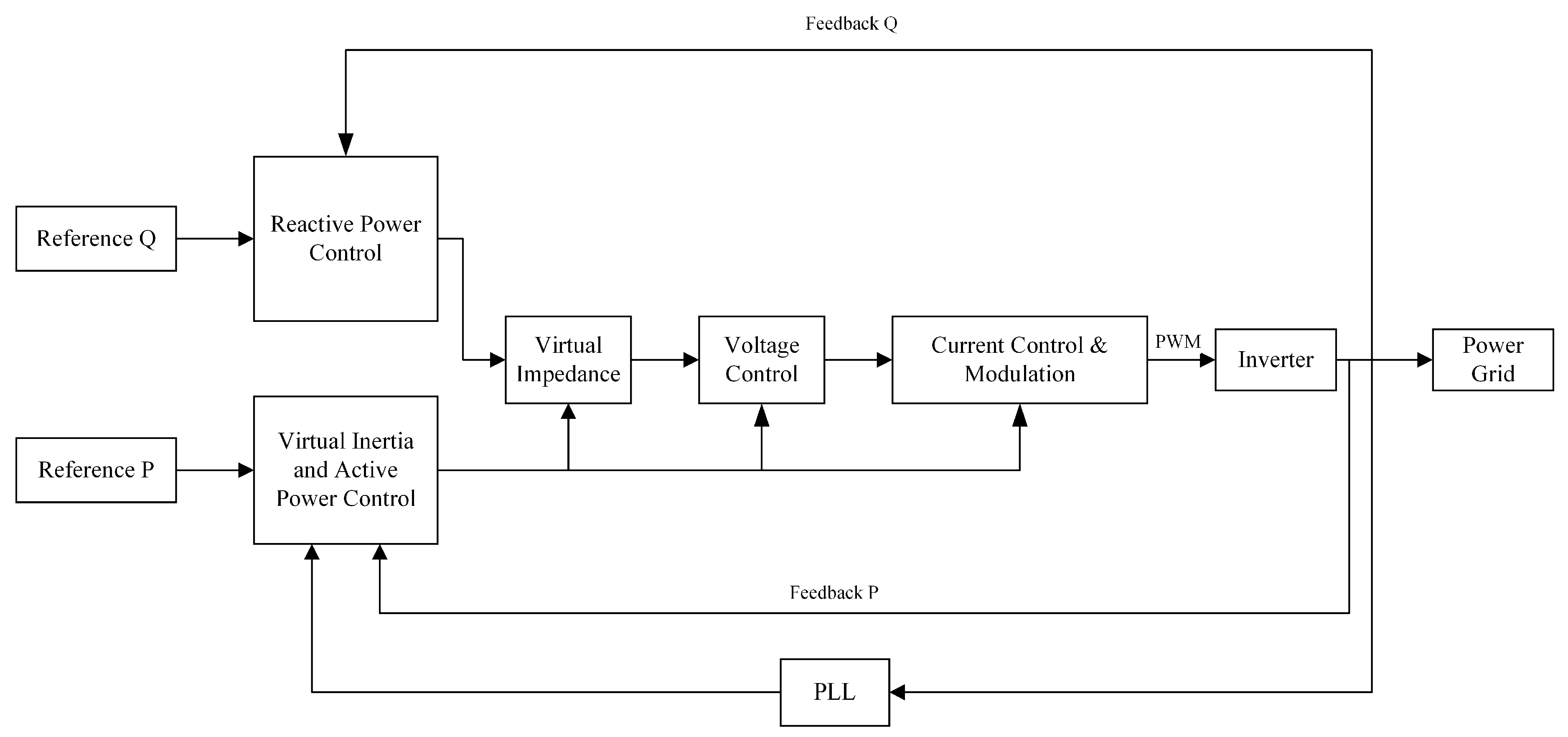
2. Implementation of VI-Based Inverters
- Reduction in frequency nadir and frequency deviation from nominal frequency (fn)
- Less overshoot and faster transient or respond time
- Less RoCoF and less steep gradient
- Faster recovery time to the nominal frequency
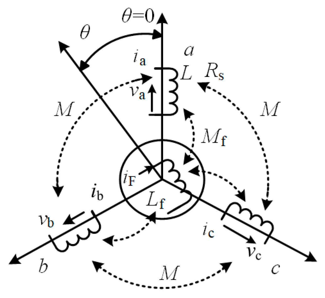
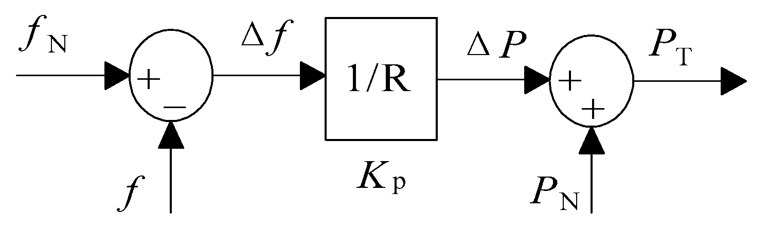
2.1. VSM
- Step 1:
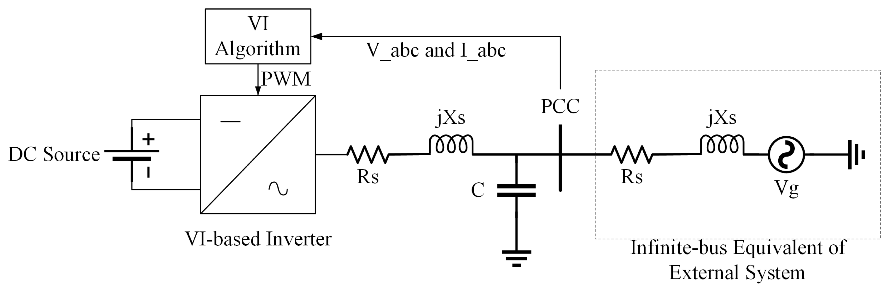
- The voltages at point of common coupling (PCC) between the output of VSM and grid are measured to compute the phase currents of the VISMA in real-time.
- Step 2:
- The computed currents are utilized as reference currents for a current-controlled inverter.
- Step 3:
- The pulse width modulation (PWM) modulator drives the inverter.
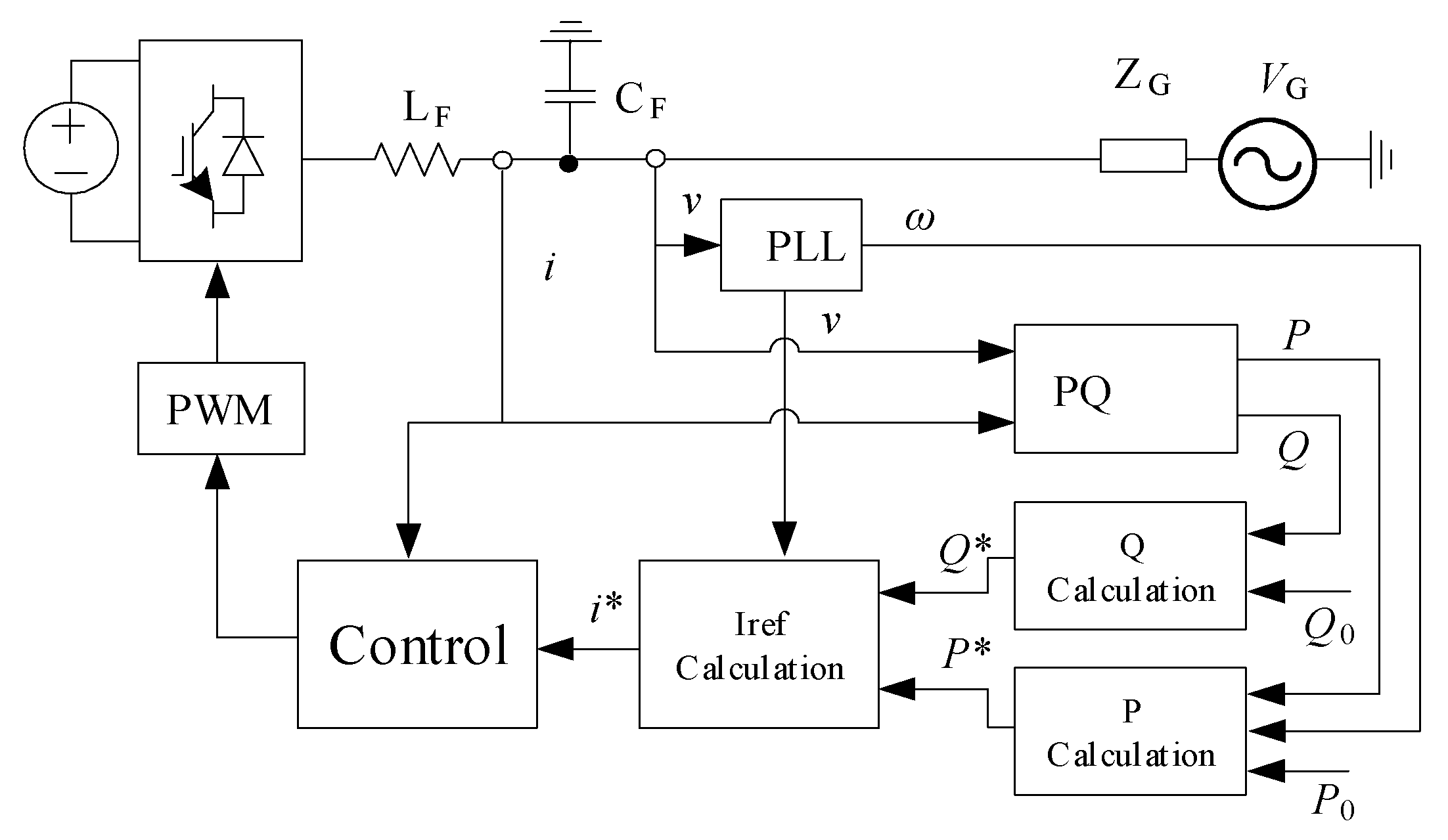
2.2. VSG
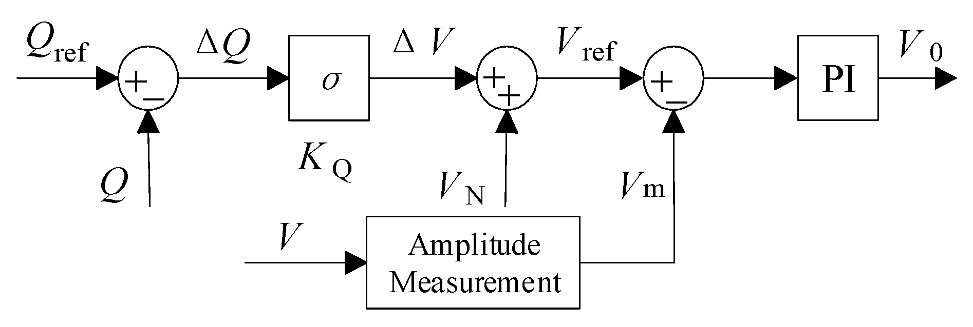
- Step 1:
- The grid voltage (V) at PCC between the output of VSG and the grid is measured and sent to the processing unit, which contains the VSG algorithm.
- Step 2:
- The processing unit uses the SM model to compute the stator current of the VSG.
- Step 3:
- Current controller sends the gate signal to inverter based on the calculated reference current (Iref).
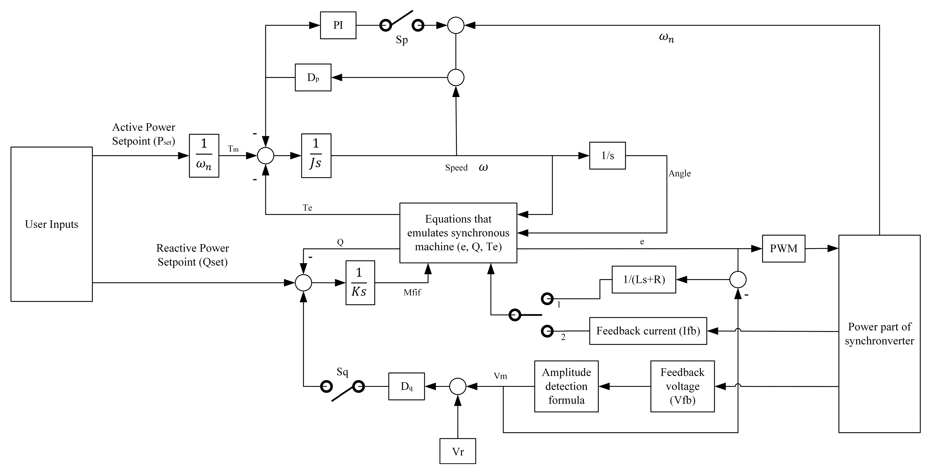
2.3. Synchronverter
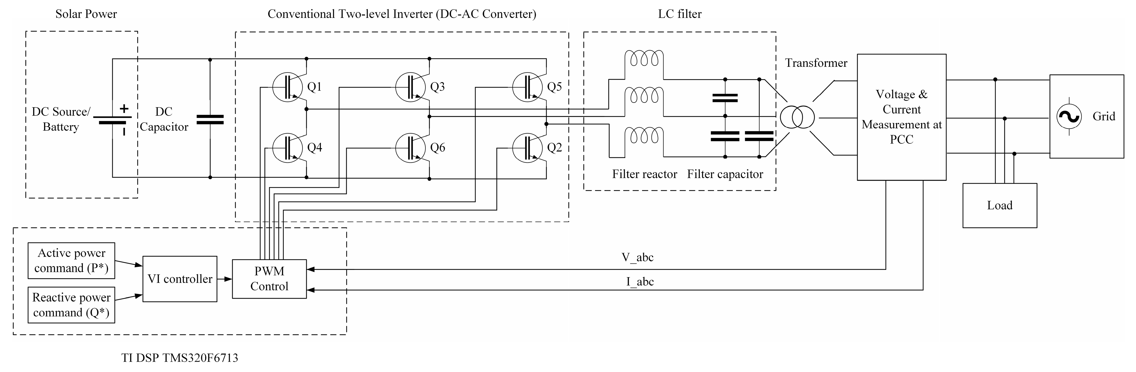
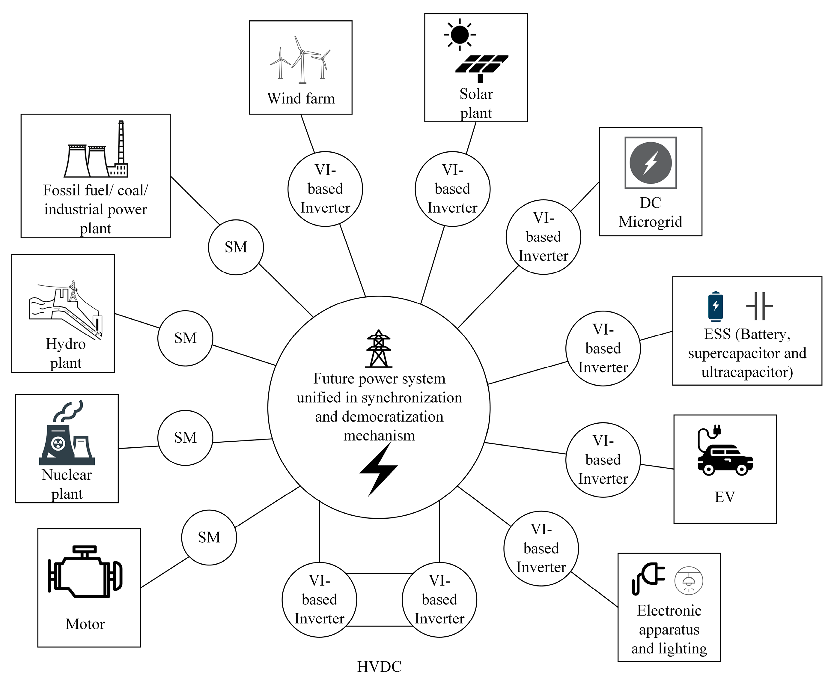
3. Applications of VI-Based Inverters
3.1. Grid-Connected RES
3.2. HVDC Transmission
3.3. ESS
3.4. Microgrid
3.5. EV
4. Comparison of VI-Based Inverters
5. Future Research
- The definition of a new grid code and standards: Grid code and standards should enable the integration of large-scale RES into the power grid, by enforcing VI emulation. The frequency regulation should be contributed by RES, and grid-forming inverter should be mandatory.
- The revision of existing reserve policy: Further technical studies and economic analysis are recommended to revise the current policy to adjust proper frequency reserve margin. It is to suit the high penetration of RES in balancing between cost and performance.
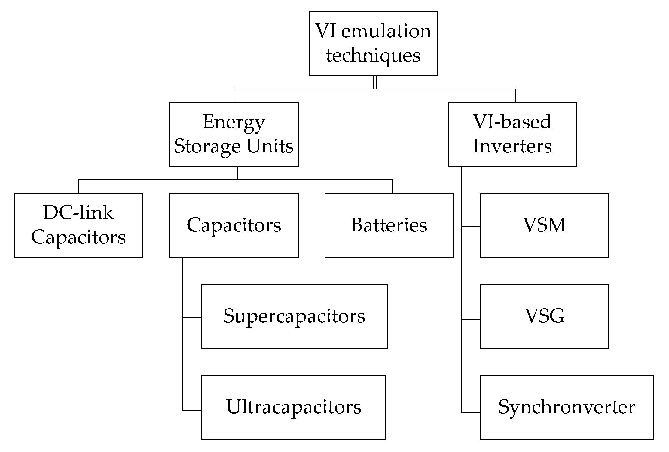
- The development of new storage technologies for frequency regulation: Both supercapacitor and ultracapacitor are promising storage technologies that are applicable to VI emulation.
5.1. Current Challenges and Limitations
5.2. ESS for VI System
5.3. Current Market and Commercialized VI Service
5.4. Industrial Implementation of VI-Based Inverters
6. Conclusions
Author Contributions
Acknowledgments
Conflicts of Interest
References
- Zsiborács, H.; Baranyai, N.H.; Vincze, A.; Zentkó, L.; Birkner, Z.; Máté, K.; Pintér, G. Intermittent Renewable Energy Sources: The Role of Energy Storage in the European Power System of 2040. Electronics 2019, 8, 729. [Google Scholar] [CrossRef]
- Ding, X.; Liu, L.; Huang, G.; Xu, Y.; Guo, J. A Multi-Objective Optimization Model for a Non-Traditional Energy System in Beijing under Climate Change Conditions. Energies 2019, 12, 1692. [Google Scholar] [CrossRef]
- Tamrakar, U.; Shrestha, D.; Malla, N.; Ni, Z.; Hansen, T.M.; Tamrakar, I.; Tonkoski, R. Comparative Analysis of Current Control Techniques to Support Virtual Inertia Applications. Appl. Sci. 2018, 8, 2695. [Google Scholar] [CrossRef]
- Zhang, D.; Wu, Y.; Xiong, L.; Zhao, C. Analysis of Inertia Characteristics of Direct-Drive Permanent-Magnet Synchronous Generator in Micro-Grid. Energies 2019, 12, 3141. [Google Scholar] [CrossRef]
- Li, Y.; Sun, Q.; Wan, D.; Lin, S. A Virtual Inertia-Based Power Feedforward Control Strategy for an Energy Router in a Direct Current Microgrid Application. Energies 2019, 12, 517. [Google Scholar] [CrossRef]
- Mehrasa, M.; Pouresmaeil, E.; Soltani, H.; Blaabjerg, F.; Calado, M.R.A.; Catalão, J.P.S. Virtual Inertia and Mechanical Power-Based Control Strategy to Provide Stable Grid Operation under High Renewables Penetration. Appl. Sci. 2019, 9, 1043. [Google Scholar] [CrossRef]
- Yan, X.; Zhang, X.; Zhang, B.; Ma, Y.; Wu, M. Research on Distributed PV Storage Virtual Synchronous Generator System and Its Static Frequency Characteristic Analysis. Appl. Sci. 2018, 8, 532. [Google Scholar] [CrossRef]
- Rodriguez, E.; Rodriguez, P. Inertia Emulation in AC/DC Interconnected Power Systems Using Derivative Technique Considering Frequency Measurement Effects. IEEE Trans. Power Syst. 2017, 32, 3338–3351. [Google Scholar]
- Rakhshani, E.; Rouzbehi, K.; Sánchez, A.J.; Tobar, A.C.; Pouresmaeil, E. Integration of Large Scale PV-Based Generation into Power Systems: A Survey. Energies 2019, 12, 1425. [Google Scholar] [CrossRef]
- Shi, R.; Zhang, X. VSG-Based Dynamic Frequency Support Control for Autonomous PV-Diesel Microgrids. Energies 2018, 11, 1814. [Google Scholar] [CrossRef]
- Kerdphol, T.; Rahman, F.S.; Mitani, Y. Virtual Inertia Control Application to Enhance Frequency Stability of Interconnected Power Systems with High Renewable Energy Penetration. Energies 2018, 11, 981. [Google Scholar] [CrossRef]
- Pagola, V.; Peña, R.; Segundo, J.; Ospino, A. Rapid Prototyping of a Hybrid PV-Wind Generation System Implemented in a Real-Time Digital Simulation Platform and Arduino. Electroncis 2019, 8, 102. [Google Scholar] [CrossRef]
- Chen, D.; Xu, Y.; Huang, A.Q. Integration of DC Microgrids as Virtual Synchronous Machines Into the AC Grid. IEEE Trans. Ind. Electron. 2017, 64, 7455–7466. [Google Scholar] [CrossRef]
- Xi, J.; Geng, H.; Ma, S.; Chi, Y.; Yang, G. Inertial response characteristics analysis and optimisation of PMSG-based VSG-controlled WECS. Renew. Power Gener. 2018, 12, 1741–1747. [Google Scholar] [CrossRef]
- Gloe, A.; Jauch, C.; Craciun, B.; Winkelmann, J. Continuous provision of synthetic inertia with wind turbines: Implications for the wind turbine and for the grid. Renew. Power Gener. 2019, 13, 668–675. [Google Scholar] [CrossRef]
- Chandrakar, P.; Saha, S.; Das, P.; Singh, A.; Debbarma, S. Grid Integration of PV System using Synchronverter. In Proceedings of the 2018 International Conference on Computation of Power, Energy, Information and Communication (ICCPEIC), Chennai, India, 28–29 March 2018. [Google Scholar]
- Amin, M.; Molinas, M. Self-synchronisation of Wind Farm in MMC-based HVDC System. IEEE Trans. Energy Convers. 2017, 32, 458–470. [Google Scholar] [CrossRef]
- Zhang, W.; Rouzbehi, K.; Luna, A.; Gharehpetian, G.B.; Rodriguez, P. Multi-terminal HVDC grids with inertia mimicry capability. Renew. Power Gener. 2016, 10, 752–760. [Google Scholar] [CrossRef]
- Wang, Y.; Yu, M.; Li, Y. Self-adaptive inertia control of DC microgrid based on fast predictive converter regulation. Renew. Power Gener. 2017, 11, 1295–1303. [Google Scholar] [CrossRef]
- Dhingra, K.; Singh, M. Frequency support in a micro-grid using virtual synchronous generator based charging station. Renew. Power Gener. 2018, 12, 1034–1044. [Google Scholar] [CrossRef]
- Li, B.; Zhang, W.; He, J. Inertia emulation and dynamic voltage support scheme for MMC-based dc systems. Renew. Power Gener. 2019, 13, 146–154. [Google Scholar] [CrossRef]
- Web of Science Group. Available online: https://mjl.clarivate.com/ (accessed on 10 September 2019).
- Zaman, M.S.U.; Hazazi, K.M.; Haider, Z.M.; Haider, R.; Kim, C.-H. Frequency Response Analysis of a Single-Area Power System with a Modified LFC Model Considering Demand Response and Virtual Inertia. Energies 2018, 11, 787. [Google Scholar] [CrossRef]
- Stephen, J. Electric Machinery Fundamentals; McGraw-Hill Education: New York, NY, USA, 2012. [Google Scholar]
- Zhong, Q.-C.; Weiss, G. Static Synchronous Generators for Distributed Generation and Renewable Energy. In Proceedings of the 2009 IEEE/PES Power Systems Conference and Exposition, Seattle, WA, USA, 15–18 March 2009. [Google Scholar]
- Liu, J.; Yang, D.; Yao, W.; Fang, R.; Zhao, H.; Wang, B. PV-based virtual synchronous generator with variable inertia to enhance power system transient stability utilizing the energy storage system. Prot. Control Mod. Power Syst. 2017, 2, 39. [Google Scholar] [CrossRef]
- Sun, R.; Chen, B.; Lv, Z.H.; Mei, J.; Zang, H.; Wei, Z.; Sun, G. Research on Robust Day-Ahead Dispatch Considering Primary Frequency Response of Wind Turbine. Appl. Sci. 2019, 9, 1784. [Google Scholar] [CrossRef]
- Fu, Y.; Wang, Y.; Zhang, X. Integrated wind turbine controller with virtual inertia and primary frequency responses for grid dynamic frequency support. Renew. Power Gener. 2017, 11, 1129–1137. [Google Scholar] [CrossRef]
- Khan, S.; Bletterie, B.; Anta, A.; Gawlik, W. On Small Signal Frequency Stability under Virtual Inertia and the Role of PLLs. Energies 2018, 11, 2372. [Google Scholar] [CrossRef]
- Miao, H.; Mei, F.; Yang, Y.; Chen, H.; Zheng, J. A Comprehensive VSM Control Strategy Designed for Unbalanced Grids. Energies 2019, 12, 1169. [Google Scholar] [CrossRef]
- Beck, H.-P.; Hesse, R. Virtual Synchronous Machine. In Proceedings of the 9th International Conference on Electrical Power Quality and Utilisation, Barcelona, Spain, 7 January 2007. [Google Scholar]
- Khajehoddin, S.A.; Karimi-Ghartemani, M.; Ebrahimi, M. Grid-Supporting Inverters With Improved Dynamics. IEEE Trans. Ind. Electron. 2019, 66, 3655–3667. [Google Scholar] [CrossRef]
- Wu, W.; Chen, Y.; Luo, A.; Zhou, L.; Zhou, X.; Yang, L.; Dong, Y.; Guerrero, J.M. A Virtual Inertia Control Strategy for DC Microgrids Analogized With Virtual Synchronous Machines. IEEE Trans. Ind. Electron. 2017, 64, 6005–6016. [Google Scholar] [CrossRef]
- Lv, Z.; Zhong, Q.-C. Control of Modular Multilevel Converters as Virtual Synchronous Machines. In Proceedings of the IEEE Power & Energy Society General Meeting, Chicago, IL, USA, 16–20 July 2017. [Google Scholar]
- Bose, U.; Chattopadhyay, S.K.; Chakraborty, C.; Pal, B. A Novel Method of Frequency Regulation in Microgrid. IEEE Trans. Ind. Appl. 2019, 55, 111–121. [Google Scholar] [CrossRef]
- Hu, W.; Wu, Z.; Dou, X.; Hu, M.; Song, H. Dynamic Analysis and Parameters Design of the Load Virtual Synchronous Machine. In Proceedings of the IEEE Power & Energy Society General Meeting, Portland, OR, USA, 24 December 2018. [Google Scholar]
- Ademola-Idowu, A.; Zhang, B. Optimal Design of Virtual Inertia and Damping Coefficients for Virtual Synchronous Machines. arXiv 2018, arXiv:preprint/1806.08488. [Google Scholar]
- D’Arco, S.; Suula, J.A.; Fosso, O.B. A Virtual Synchronous Machine implementation for distributedcontrol of power converters in SmartGrids. Electr. Power Syst. Res. 2015, 122, 180–197. [Google Scholar] [CrossRef]
- Zhang, B.; Yan, X.; Li, D.; Zhang, X.; Han, J.; Xiao, X. Stable Operation and Small-Signal Analysis of Multiple Parallel DG Inverters Based on a Virtual Synchronous Generator Scheme. Energies 2018, 11, 203. [Google Scholar] [CrossRef]
- Ma, Y.; Lin, Z.; Yu, R.; Zhao, S. Research on Improved VSG Control Algorithm Based on Capacity-Limited Energy Storage System. Energies 2018, 11, 677. [Google Scholar] [CrossRef]
- Liu, J.; Hossain, M.; Lu, J.; Raf, F.; Li, H. A hybrid AC/DC microgrid control system based on a virtual synchronous generator for smooth transient performances. Electr. Power Syst. Res. 2018, 162, 169–182. [Google Scholar] [CrossRef]
- Su, J.; Li, W.; Liu, H.; Meng, F.; Wang, L.; Han, X. Application of Virtual Synchronous Generator in Solar Power Generation. J. Phys. Conf. Ser. 2018, 1087. [Google Scholar] [CrossRef]
- Andalib-Bin-Karim, C.; Liang, X.; Zhang, H. Fuzzy-Secondary-Controller-Based Virtual Synchronous Generator Control Scheme for Interfacing Inverters of Renewable Distributed Generation in Microgrids. IEEE Trans. Ind. Appl. 2018, 54, 1047–1061. [Google Scholar] [CrossRef]
- Abdolwahhab, F.; Qobad, S.; Bevrani, H. Robust Frequency Control of Microgrids Using an Extended Virtual Synchronous Generator. IEEE Trans. Ind. Appl. 2018, 33, 6289–6297. [Google Scholar]
- Wang, F.; Zhang, L.; Feng, X.; Guo, H. An Adaptive Control Strategy for Virtual Synchronous Generator. IEEE Trans. Ind. Appl. 2018, 54, 5124–5133. [Google Scholar] [CrossRef]
- Dong, S.; Chen, Y.C. Reducing Transient Active- and Reactive-power Coupling in Virtual Synchronous Generators. In Proceedings of the IEEE 28th International Symposium on Industrial Electronics (ISIE), Vancouver, BC, Canada, 12–14 June 2019; pp. 1090–1095. [Google Scholar]
- Zhang, B.; Li, D.; Wang, Y.; Yan, X. Self-adaptable reactive power-voltage controller for virtual synchronous generators. J. Eng. 2019, 2019, 2969–2973. [Google Scholar] [CrossRef]
- Liu, J.; Miura, Y.; Ise, T. Comparison of Dynamic Characteristics Between Virtual Synchronous Generator and Droop Control in Inverter-Based Distributed Generators. IEEE Trans. Power Electron. 2016, 31, 3600–3611. [Google Scholar] [CrossRef]
- Li, B.; Zhou, L.; Yu, X.; Zheng, C.; Liu, J. Improved power decoupling control strategy based on virtual synchronous generator. Power Electron. 2017, 10, 462–470. [Google Scholar] [CrossRef]
- Shi, K.; Ye, H.; Song, W.; Zhou, G. Virtual Inertia Control Strategy in Microgrid Based on Virtual Synchronous Generator Technology. IEEE Access 2018, 6, 27949–27957. [Google Scholar] [CrossRef]
- Ma, Y.; Cao, W.; Yang, L.; Wang, F.; Tolbert, L.M. Virtual Synchronous Generator Control of Full Converter Wind Turbines With Short-Term Energy Storage. IEEE Trans. Ind. Electron. 2017, 64, 8821–8831. [Google Scholar] [CrossRef]
- Yazdi, S.S.H.; Milimonfared, J.; Fathi, S.H.; Rouzbehi, K.; Rakhshani, E. Analytical modeling and inertia estimation of VSG-controlled Type 4 WTGs: Power system frequency response investigation. Electr. Power Energy Syst. 2019, 107, 446–461. [Google Scholar] [CrossRef]
- Cao, Y.; Wang, W.; Li, Y.; Tan, Y.; Chen, C.; He, L.; Hager, U.; Rehtanz, C. A Virtual Synchronous Generator Control Strategy for VSC-MTDC Systems. IEEE Trans. Energy Convers. 2018, 33, 750–761. [Google Scholar] [CrossRef]
- Rahman, F.S.; Kerdphol, T.; Watanabe, M.; Mitani, Y. Optimization of virtual inertia considering system frequency protection scheme. Electr. Power Energy Syst. 2019, 170, 294–302. [Google Scholar] [CrossRef]
- Kerdphol, T.; Rahman, F.S.; Mitani, Y.; Watanabe, M.; Küfeoǧlu, S. Robust Virtual Inertia Control of an Islanded Microgrid Considering High Penetration of Renewable Energy. IEEE Access 2018, 6, 625–636. [Google Scholar] [CrossRef]
- Magdy, G.; Shabib, G.; Elbaset, A.A.; Mitani, Y. Renewable power systems dynamic security using a new coordination of frequency control strategy based on virtual synchronous generator and digital frequency protection. Electr. Power Energy Syst. 2019, 109, 351–368. [Google Scholar] [CrossRef]
- Rathore, B.; Chakrabarti, S.; Anand, S. Frequency response improvement in microgrid using optimized VSG control. In Proceedings of the 2016 National Power Systems Conference, Bhubaneswar, India, 9–21 December 2016. [Google Scholar]
- Sekizaki, S.; Matsuo, K.; Sasaki, Y.; Yorino, N.; Nakamura, Y.; Zoka, Y.; Shimizu, T.; Nishizaki, I. A Development of Single-phase Synchronous Inverter and Integration to Single-phase Microgrid effective for frequency stability enhancement. IFAC-PapersOnLine 2018, 51, 245–250. [Google Scholar] [CrossRef]
- Hu, P.; Chen, H.; Cao, K.; Hu, Y.; Kai, D.; Chen, L.; Wang, Y. Coordinated Control of Multiple Virtual Synchronous Generators in Mitigating Power Oscillation. Energies 2018, 11, 2788. [Google Scholar] [CrossRef]
- Huang, X.; Wang, K.; Li, G.; Zhang, H. Virtual Inertia-Based Control Strategy of Two-Stage Photovoltaic Inverters for Frequency Support in Islanded Micro-Grid. Electronics 2018, 7, 340. [Google Scholar] [CrossRef]
- Zhong, Q.-C.; Weiss, G. Synchronverters: Inverters That Mimic Synchronous Generators. IEEE Trans. Ind. Electron. 2011, 58, 1259–1267. [Google Scholar] [CrossRef]
- Zhong, Q.-C.; Nguyen, P.-L.; Ma, Z.; Sheng, W. Self-Synchronized Synchronverters: Inverters Without a Dedicated Synchronization Unit. IEEE Trans. Power Electron. 2014, 29, 617–630. [Google Scholar] [CrossRef]
- Reed, J.K.; Zhong, Q.-C.; Saniie, J. Digital Synchronverter Design Flow for Renewable Energy. In Proceedings of the 2017 IEEE International Conference on Electro Information Technology, Lincoln, NE, USA, 14–17 May 2017. [Google Scholar]
- Zhong, Q.-C.; Konstantopoulos, G.C.; Ren, B.; Krstic, M. Improved Synchronverters with Bounded Frequency and Voltage for Smart Grid Integration. IEEE Trans. Smart Grid 2018, 9, 786–796. [Google Scholar] [CrossRef]
- Thomas, A.; Smitha, S.D. A Self-synchronized Synchronverter Technology for Integrating PV Inverters to Grid without Using a Phase Locked Loop. Int. J. Innov. Res. Technol. 2015, 2, 24–29. [Google Scholar]
- Shao, T.; Zheng, T.Q.; Li, H.; Zhang, X. Parameter design and hot seamless transfer of single-phase synchronverter. Electr. Power Energy Syst. 2018, 160, 63–70. [Google Scholar] [CrossRef]
- Younis, T.; Ismeil, M.; Orabi, M.; Hussain, E.K. A Single-phase Self-synchronized Synchronverter with Bounded Droop Characteristics. In Proceedings of the 2018 IEEE Applied Power Electronics Conference and Exposition (APEC), San Antonio, TX, USA, 4–8 March 2018. [Google Scholar]
- Aouini, R.; Nefzi, I.; Kilani, K.B.; Elleuch, M. Exploitation of Synchronverter Control to Improve the Integration of Renewable Sources to the Grid. J. Electr. Syst. 2017, 13, 543–557. [Google Scholar]
- Dong, S.; Chen, Y.C. A Method to Directly Compute Synchronverter Parameters for Desired Dynamic Response. IEEE Trans. Energy Convers. 2018, 33, 814–825. [Google Scholar] [CrossRef]
- Blau, M.; Weiss, G. Synchronverters used for damping inter-area oscillations in two-area power systems. Int. Conf. Renew. Energ. Power Qual. 2018, 1, 45–50. [Google Scholar] [CrossRef]
- Younis, T.; Ismeil, M.; Hussain, E.K.; Orabi, M. An Improved Single-phase Self-synchronized Synchronverter with Enhanced Dynamics and Current Limitation Capability. Res. J. 2018, 12, 337–344. [Google Scholar]
- Wang, X.; Chen, L.; Sun, D.; Zhang, L.; Nian, H. A Modified Self-Synchronized Synchronverter in Unbalanced Power Grids with Balanced Currents and Restrained Power Ripples. Energies 2019, 12, 923. [Google Scholar] [CrossRef]
- Aouini, R.; Marinescu, B.; Kilani, K.B.; Elleuch, M. Synchronverter-Based Emulation and Control of HVDC Transmission. IEEE Trans. Power Syst. 2015, 31, 278–286. [Google Scholar] [CrossRef]
- Zhang, W.; Cantarellas, A.M.; Rocabert, J.; Luna, A.; Rodriguez, P. Synchronous Power Controller With Flexible Droop Characteristics for Renewable Power Generation Systems. IEEE Trans. Sustain. Energy 2016, 7, 1572–1582. [Google Scholar] [CrossRef]
- Barzilai, G.; Marcus, L.; Weiss, G. Energy Storage Systems-Grid Connection Using Synchronverters. In Proceedings of the ISCEE International Conference on the Science of Electrical Engineering, Eilat, Israel, 16–18 November 2016. [Google Scholar]
- Tamrakar, U.; Shrestha, D.; Maharjan, M.; Bhattarai, B.P.; Hansen, T.M.; Tonkoski, R. Virtual Inertia: Current Trends and Future Directions. Appl. Sci. 2017, 7, 654. [Google Scholar] [CrossRef]
- Yang, S.; Fang, J.; Tang, Y.; Qiu, H.; Dong, C.; Wang, P. Modular Multilevel Converter Synthetic Inertia-Based Frequency Support for Medium-Voltage Microgrids. IEEE Trans. Ind. Electron. 2019, 66, 8992–9002. [Google Scholar] [CrossRef]
- Bonfiglio, A.; Invernizzi, M.; Labella, A.; Procopio, R. Design and Implementation of a Variable Synthetic Inertia Controller for Wind Turbine Generators. IEEE Trans. Power Syst. 2019, 34, 754–764. [Google Scholar] [CrossRef]
- Rajan, E.; Amrutha, S. Synchronverter based HVDC transmission. In Proceedings of the Innovations in Power and Advanced Computing Technologies (i-PACT), Vellore, India, 21–22 April 2017. [Google Scholar]
- Yan, X.; Li, J.; Zhang, B.; Jia, Z.; Tian, Y.; Zeng, H.; Lv, Z. Virtual Synchronous Motor Based-Control of a Three-Phase Electric Vehicle Off-Board Charger for Providing Fast-Charging Service. Appl. Sci. 2018, 8, 856. [Google Scholar] [CrossRef]
- Liu, D. Cluster Control for EVs Participating in Grid Frequency Regulation by Using Virtual Synchronous Machine with Optimized Parameters. Appl. Sci. 2019, 9, 1924. [Google Scholar] [CrossRef]
- Yuan, C.; Xie, P.; Yang, D.; Xiao, X. Transient Stability Analysis of Islanded AC Microgrids with a Significant Share of Virtual Synchronous Generators. Energies 2018, 11, 44. [Google Scholar] [CrossRef]
- Chamorro, H.R.; Riaño, I.; Gerndt, R.; Zelinka, I.; Gonzalez-Longatt, F.; Sood, V.K. Synthetic inertia control based on fuzzy adaptive differential evolution. Electr. Power Energy Syst. 2019, 105, 803–813. [Google Scholar] [CrossRef]
- Beltran, O.; Peña, R.; Segundo, J.; Esparza, A.; Muljadi, E.; Wenzhong, D. Inertia Estimation of Wind Power Plants Based on the Swing Equation and Phasor Measurement Units. Appl. Sci. 2018, 8, 2413. [Google Scholar] [CrossRef]
- Nanou, S.I.; Papakonstantinou, A.G.; Papathanassiou, S.A. A generic model of two-stage grid-connected PV systems with primary frequency response and inertia emulation. Electr. Power Energy Syst. 2015, 127, 186–196. [Google Scholar] [CrossRef]
- Ofir, R.; Markovic, U.; Aristidou, P.; Hug, G. Droop vs. Virtual Inertia: Comparison from the Perspective of Converter Operation Mode. In Proceedings of the 2018 IEEE International Energy Conference (ENERGYCON), Limassol, Cyprus, 3–7 June 2018. [Google Scholar]
- Yan, X.; Zhang, W. Review of VSG Control-Enabled Universal Compatibility Architecture for Future Power Systems with High-Penetration Renewable Generation. Appl. Sci. 2019, 9, 1484. [Google Scholar] [CrossRef]
- Li, M.; Huang, W.; Tai, N.; Yu, M. Lyapunov-Based Large Signal Stability Assessment for VSG Controlled Inverter-Interfaced Distributed Generators. Energies 2018, 11, 2273. [Google Scholar] [CrossRef]
- Negri, S.; Tironi, E.; Danna, D.S. Integrated Control Strategy for Islanded Operation in Smart Grids: Virtual Inertia and Ancillary Services. In Proceedings of the 2017 IEEE International Conference on Environment and Electrical Engineering, Milan, Italy, 6–9 June 2017. [Google Scholar]
- Agranat, Q.; MacGill, I.; Bruce, A. Fast Frequency Markets under High Penetrations of Renewable Energy in the Australian National Electricity Market. In Asia-Pacific Solar Research Conference; UNSW: Sydney, QLD, Australia, 2015. [Google Scholar]
- Zeng, Z.; Li, X.; Shao, W. Multi-functional grid-connected inverter: Upgrading distributed generator with ancillary services. Renew. Power Gener. 2018, 12, 797–805. [Google Scholar] [CrossRef]
- Jaalam, N.; Rahim, N.; Bakar, A.; Tan, C.; Haidar, A.M. A comprehensive review of synchronization methods for grid-connected converters of renewable energy source. Renew. Sustain. Energy Rev. 2016, 59, 1471–1481. [Google Scholar] [CrossRef]
- Jadhav, G.N.; Shaikh, S.J.; Buwa, O.N. Challenges in Implementation of Virtual Synchronous Generator. Compend. Tech. Pap. Springer 2018, 487, 209–221. [Google Scholar]
- Mohammed, O.O.; Otuoze, A.O.; Salisu, S.; Ibrahim, O.; Rufa’i, N.A. Virtual Synchronous Generator: An Overview. Niger. J. Technol. 2019, 38, 153–164. [Google Scholar] [CrossRef]
- Fang, J.; Lin, P.; Li, H.; Yang, Y.; Tang, Y. An Improved Virtual Inertia Control for ThreePhase Voltage Source Converters Connected to a Weak Grid. IEEE Trans. Power Electron. 2018, 34, 8660–8670. [Google Scholar]
- Fang, J.; Tang, Y.; Li, H.; Li, X. A Battery/Ultracapacitor Hybrid Energy Storage System for Implementing the Power Management of Virtual Synchronous Generators. IEEE Trans. Power Electron. 2017, 33, 2820–2824. [Google Scholar] [CrossRef]
- Luo, X.; Wang, J.; Dooner, M.; Clarke, J. Overview of current development in electrical energy storage technologies and the application potential in power system operation. Appl. Energy 2015, 137, 511–536. [Google Scholar] [CrossRef]
- Fang, J.; Li, H.; Tang, Y.; Blaabjerg, F. On the Inertia of Future More-Electronics Power Systems. IEEE J. Emerg. Sel. Top. Power Electron. 2018, 7, 2130–2146. [Google Scholar] [CrossRef]
- Karapanos, V.; de Haan, S.; Zwetsloot, K. Real time simulation of a power system with VSG hardware in the loop. In Proceedings of the 37th Annual Conference of the IEEE Industrial Electronics Society (IECON), Melbourne, Australia, 7–10 November 2011. [Google Scholar]
- Thiesen, H.; Jauch, C.; Gloe, A. Design of a System Substituting Today’s Inherent Inertia in the European Continental Synchronous Area. Energies 2016, 9, 582. [Google Scholar] [CrossRef]


| Merits | Demerits |
|---|---|
| - Suppress grid disturbances - Automatic synchronization and power-sharing ability - For both stand-alone and microgrid operation - Conceptual simplicity | - Long TET because of Park Transformation - Numerical instability - Complex PLL implementation |
| Type of Application | Ref. | Type of VSM/VISMA | Highlights of the Control Strategy |
|---|---|---|---|
| DC Microgrids | [33] | VSM for DC Microgrids | VSM is designed to improve the inertia of DC microgrid and reduce the fluctuation of the DC bus voltage. |
| MMC | [34] | VSM for MMC | VSM control strategy is applied for MMC to operate and control it as an SG. |
| General | [32] | Enhanced VSM | The enhanced VSM (eVSM) exhibits larger inertia which eliminates the requirement of a large DC-link element or BESS. |
| Microgrid | [35] | VSM with EES for a stand-alone microgrid | ESS is integrated by VSM-based inverter to the grid and a double second-order generalized integrator PLL to regulate frequency during transient conditions. |
| Load | [36] | Load VSM | Load virtual synchronous machine topology and corresponding control strategy to mimic the characteristics of an SM. |
| General | [37] | Optimal design of the VI and damping coefficient | H2 norm objective function is utilized to calculate the coefficient values for VSM. |
| Smart grids | [38] | VSM for distributed control of power converters in smart grids | A VSM is designed to provide smart grid support and allow a seamless transition between grid-connected or islanded operation. |
| Merits | Demerits |
|---|---|
| - Enable load sharing among parallel-connected units - Unlike SG, the parameter of VSG (H and D) can be controlled in real-time - Fast response in tracking steady-state frequency - No magnetic saturation and eddy current losses - Can act as a motor - Simple implementation - Typical current-source implementation with inherent overcurrent protection | - Long execution time because of Park Transformation - Instability due to the presence of PLL especially in weak grid - The presence of frequency derivative introduced noise - Unable to implement in islanded mode since it is not a grid forming unit - It emulates inertia during frequency variation, not input power variation |
| Type of Application | Ref. | Type of VSG | Highlights of the Control Strategy |
|---|---|---|---|
| General | [43] | Fuzzy Secondary Controller (FSC) | Fuzzy logic control (FLC) algorithm, which is a type of artificial intelligence (AI) method is applied for VSG control. |
| [49] | Power decoupling control strategy | Active power and reactive power are independently controlled for the enhanced decoupling strategy for VSGs. | |
| [45] | Adaptive Control for VSG | The inertia and damping coefficient of VSG is adjusted flexibly to achieve better dynamic performance. | |
| Wind Energy | [50] | VI Control Strategy in Microgrid | The state information of the generator and ESS are utilized for VI control to regulate output frequency in a direct and accurate manner. |
| [51] | VSG with Short-Term Energy Storage | The VSG is integrated with short-term minute-level energy storage. | |
| [52] | Inertia estimation of VSG-controlled Type 4 WTGs | The wind turbine generator is controlled by VSG based on motion equation concept. | |
| HVDC | [53] | VSG Control Strategy for HVDC | VSG control is adapted for voltage-source converter-based multiterminal high-voltage direct current |
| Frequency protection | [54] | PSO-based VSG | Particle swarm optimization (PSO) is applied to optimize VI constant of VSG. |
| Microgrid | [44] | Extended VSG for Microgrid | The H∞ control method is applied to tune the virtual parameters of VSG. |
| [55] | Robust VI Control by H infinity control method | A robust H∞ based VI controller is designed to minimize the frequency deviations of an islanded microgrid. | |
| [56] | VSG with digital frequency protection | VSG is designed to stabilize the system frequency with digital frequency protection to interface with small and large scales of power systems. | |
| [57] | Optimized VSG Control by PSO | PSO is utilized to optimize the values of virtual inertia constant and virtual damping factor. | |
| [41] | A hybrid AC/DC microgrid control system based on a VSG | An improved VSG with a pre-synchronization controller is applied for hybrid AC to DC microgrid system. |
| Merits | Demerits |
|---|---|
| - Self-synchronizing to the grid frequency without any additional controller, unless there is a large disturbance - Scalable by parallel connection in sharing real and reactive power - Technological maturity-control synchronverter is the same way as controlling a synchronous generator - Robust and dynamic control of PQ and voltage phase as well frequency - Does not require PLL for self-synchronizing synchronverter - Frequency derivative which known for noise is not presented | - No overcurrent protection due to voltage-source implementation - Differential equation complexity causes numerical instability - Voltage-source control has no inherent protection against severe grid transient - Require external protection for safe operation |
| Type of Application | Ref. | Type of Synchronverter | Highlights of Control Strategy |
|---|---|---|---|
| General | [66] | Hot seamless transfer | Additional seamless transfer branch to enable single-phase synchronverter acts as an uninterrupted power source |
| [62] | Self-synchronized synchronverter | Modification on synchronverter which does not require PLL to synchronize itself to the grid. Instead of PLL, virtual impedance is utilized. | |
| [71] | Self-synchronized synchronverter with enhanced dynamics and current limitation | The droop ratio is decoupled from the damping coefficient and a PR current inner loop is added. | |
| [64] | Bounded frequency and voltage | Integration of bounded frequency and voltage to ensure synchronverter always operates in a stable region. | |
| [72] | Modified self-synchronized synchronverter | A filter has been used in filter-based current feeding loops to eliminate the power ripples. | |
| Solar PV | [65] | Grid-connected PV inverters without PLL | Self-synchronizing inverter without the need of PLL is able to interface the solar PV system to the utility grid. |
| [67] | Bounded droop control | It provides the synchronverter with power limitation and more flexible design process. | |
| [16] | Grid integration of PV system using synchronverter | Interface solar photovoltaic module was connected as DC source to the inverter. The inverter was connected to the grid without any transformer. | |
| HVDC | [73] | Synchronverter-based emulation and control of HVDC | Control strategy for HVDC based on synchronverter |
| Renewable Power Generation Systems | [74] | Flexible droop characteristics | The controller has flexibility since it avoids the constraint between the damping and droop characteristics in power regulating loop. |
| Wind Farm | [17] | Self-synchronization of wind farm in MMC-based HVDC | Synchronverter is implemented on the wind energy conversion system converter to synchronize them to the Modular MMC-based HVDC system. |
| ESS | [75] | Grid-connected ESS using synchronverters | Lithium-ion batteries as ESS is connected to the power grid via synchronverters. It improves the stability of the grid and supplies power during high demand. |
| Power system | [70] | Synchronverter for damping inter-area oscillations in two-area power systems | Synchronverter is utilized to improve the damping of inter-area oscillations and transient stability of a power system. |
| Parameter | VSM | VSG | Synchronverter |
|---|---|---|---|
| Converter type | VSC | ||
| Inverter type | Current-controlled | Voltage-controlled | |
| Based on | SM | SG | |
| Model order | Up to seventh order | Up to second order | |
| Complexity | High | Medium | |
| Grid mode | Yes | ||
| Standalone mode | Not applicable | Yes | |
| Grid viewpoint | Different than SG | As an SG | |
| Dependency on the tracking of ref. I or V | Yes | No | |
| Cost | High | ||
| General mathematical model | |||
| Algorithm Implementation Complexity | Moderate—higher order of SG model | Hard—parameters difficult to adjust and dependent on unstable PLL | Easy—second-order SG model and can operate with or without PLL |
| Readiness for commercial and industrial inverter | Ready for full commercialization: ABB, Schneider Electric, FREQCON | ||
| Readiness for the grid or power system operator | Hydro-Québec TransÉnergie’s (HQT’s) Canada; National Grid Electricity System Operator (NGESO), Great Britain; Electric Reliability Council of Texas grid; South African Grid Code | ||
| Research and Development (R&D) Funding | SYNDEM | VSYNC project (EU), 2007; IEPE Group; ISE Lab; Kawasaki Heavy Industries (KHI) | Synchronverter- European Commission, Q3 Energie GmbH & Co. |
| Type of Inverter | Grid-Forming | Grid-Following |
|---|---|---|
| VI-based Inverters | Synchronverter and VSM | VSG |
| Function | Supporting the grid | Following the grid |
| Source behavior from grid viewpoint | Voltage source | Current source |
| Set grid voltage and frequency | Yes | No (Follow the grid) |
| Provide active and reactive power to the load via voltage | Yes | Inject active and reactive power |
| Response | Slow response due to large inertia | Fast response to the intermittent |
| Inertial response | Yes | No |
| Buffer | Yes | No |
| Instable due to intermittent irradiance (PV) or wind | No | Yes |
| Support weak grid operation | Yes | No |
| Islanding | Yes | No |
| Deviation from the nominal frequency | Higher | Lower |
| RoCoF | Similar | |
| Peak power injection during disturbance | Smaller | Larger |
| Injection of active power | Not application | Yes |
| The manipulation of frequency of voltage | Yes | Not application |
| Order of Model | Model Implementation | Reference Voltage | Reference Current | Reference Power (P&Q) | Merit | Demerit | |
|---|---|---|---|---|---|---|---|
| Direct PWM | V&I Controllers | ||||||
| Seventh-order model | Electric, magnetic, swing equation of stator and rotor winding | Possible | Possible | VSM | N/A | Full representation of SG dynamics with all parameters | Highly complex and high computational burden |
| Fifth- or fourth-order model | Electric, magnetic, swing equation of stator winding | VSM | Possible | VSM | N/A | Best balance between complexity and computational burden | Only stator winding is considered compared to seventh-order model |
| Second-order model | Swing equation and voltage amplitude is given by the reactive power controller | Synchronverter | Ongoing research | Conceptual | VSG | Most common scheme of converter implementation for a simple and close imitation | Lack of some parameters compared to seventh-order model |
| First-order model | Inertial emulation by power response calculated from grid voltage tracking | N/A | N/A | Possible | VSYNC and VSG | Simplest and fastest implementation | Incapable of isolated operation and insufficient modeling |
© 2019 by the authors. Licensee MDPI, Basel, Switzerland. This article is an open access article distributed under the terms and conditions of the Creative Commons Attribution (CC BY) license (http://creativecommons.org/licenses/by/4.0/).
Share and Cite
Yap, K.Y.; Sarimuthu, C.R.; Lim, J.M.-Y. Virtual Inertia-Based Inverters for Mitigating Frequency Instability in Grid-Connected Renewable Energy System: A Review. Appl. Sci. 2019, 9, 5300. https://doi.org/10.3390/app9245300
Yap KY, Sarimuthu CR, Lim JM-Y. Virtual Inertia-Based Inverters for Mitigating Frequency Instability in Grid-Connected Renewable Energy System: A Review. Applied Sciences. 2019; 9(24):5300. https://doi.org/10.3390/app9245300
Chicago/Turabian StyleYap, Kah Yung, Charles R. Sarimuthu, and Joanne Mun-Yee Lim. 2019. "Virtual Inertia-Based Inverters for Mitigating Frequency Instability in Grid-Connected Renewable Energy System: A Review" Applied Sciences 9, no. 24: 5300. https://doi.org/10.3390/app9245300
APA StyleYap, K. Y., Sarimuthu, C. R., & Lim, J. M.-Y. (2019). Virtual Inertia-Based Inverters for Mitigating Frequency Instability in Grid-Connected Renewable Energy System: A Review. Applied Sciences, 9(24), 5300. https://doi.org/10.3390/app9245300