Featured Application
The grouted sleeve lapping connector reported in this work, which is featured by a large sleeve inner diameter and low production cost, can be used to connect the components in precast concrete structures, such as a precast column and shear wall.
Abstract
Compared to grouted splice connectors that have been widely used in constructing precast concrete structures, grouted sleeve lapping connectors have the advantages of a large sleeve interior diameter and low manufacturing cost. In this study, 16 grouted sleeve lapping connectors and three grouted splice connectors were tested under an incremental tensile load. The differences in their tensile capacities and failure modes, especially the mechanical properties of the grouted sleeve lapping connectors, were investigated. It was found that the tensile capacities of the grouted sleeve lapping connectors were up to 2.45 times that of the grouted splice connectors when the sleeve inner surfaces were smooth. All of the grouted sleeve lapping connectors failed by a bar tensile fracture or bar-grout slip, whereas the only failure mode of the grouted splice connectors was grout-sleeve failure. The bond stress distribution around the inserted bar in the grouted sleeve lapping connector was similar to the bond stress distribution around a single bar anchored in concrete. The ultimate hoop compressive strain of the sleeve and the corresponding load increase with greater lap length. In addition, an approximate mechanical model with high reliability was put forward to describe the mechanical properties of the grouted sleeve lapping connector.
1. Introduction
Compared to cast-in-situ concrete structures, precast concrete structures have the advantages of design-build efficiency, aesthetical versatility, reduced costs, low maintenance, and superior resistance to disasters [1,2,3,4]. However, many long-standing issues of precast structures, such as the defects of the connectors between precast components, always cause difficulties in the construction procedure and safety hazard under service as well as disasters. Although these issues need comprehensive research, most of the existing investigations are related to cast-in-situ structures and the studies on precast structures, especially those that focus on the connectors of precast structures, which have yet to be sufficient.
To guarantee the performance of precast concrete structures, the reinforcement bars in components of the structures need to be well spliced. Thus, the grouted splice connector has been widely studied by researchers from all over the world [5,6,7,8]. For instance, Parks et al. [9] investigated the grouted splice connector, which connected a reinforced precast concrete bridge pier cap and a precast column in America. Li et al. [10] studied the dynamic response of precast concrete beams connected by the grouted splice connector in China. Tullini and Minghini [11] conducted an experimental research on the behavior of precast reinforced concrete column-to-column connections made with grouted sleeve splices in Italy. Ling et al. [12] studied the behavior of the precast concrete wall panels, which was connected by a grouted splice connector in Malaysia. Figure 1 is a sketch of a vertically-connected precast concrete shear wall system with a grouted splice connector. A sleeve is embedded at the bottom of the upper precast shear wall in advance during the fabrication process. In the field, the sleeve is placed onto the bar protruding from the top of the lower precast shear wall. Then, grout is poured into the sleeve through the grouting hole until the sleeve is full [13]. The spliced bars must be aligned and positioned at the center of the sleeve for the tensile capacity of the connector to develop fully [14]. The force in one bar is transferred from the grout to the sleeve, and, by the same way, to the other bar [15]. Thus, the grout in the sleeve plays a critical role in force transfer. Therefore, it is essential to completely fill the sleeve inner cavity with grout.
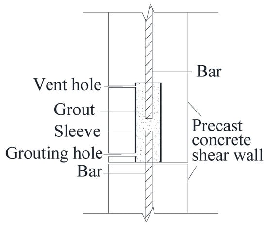
Figure 1.
Sketch of the grouted splice connector.
According to the specification JGJ 355-2015 [16], for bars with diameters of 12–25 mm and 28–40 mm, the minimum differences between the sleeve inner diameter and the bar diameter are 10 mm and 15 mm, respectively. However, most sleeve inner diameters designed by practitioners are less than 50 mm [17,18,19,20], since a smaller sleeve diameter will provide sufficient confinement to achieve a higher bond strength between the bar and the grout, which increases the tensile capacity [21,22]. However, a small sleeve inner diameter always creates difficulties in on-site construction. One problem is that insufficient space between the bar and the sleeve cavity will cause an incomplete fill of grout (Figure 2), which weakens the ability of the connector to transfer force. There is a more serious secondary problem. The protruded bar inevitably leans during transportation and construction. Usually, construction workers need to exert force to correct the inclination of the bar so that the bar can be inserted into the sleeve to align with the other bar. However, when the angle of the incline of the bar is relatively large, and the sleeve inner diameter is relatively small, some workers choose to cut off the inclined bar for ease of construction, which severely weakens the connection performance of the splice.
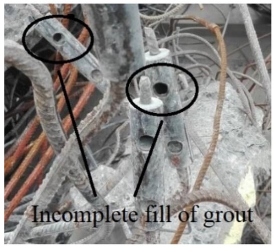
Figure 2.
Incomplete fill of grout in grouted splice connector.
Grout-sleeve bond failure is a typical but undesirable failure mode in grout splice connector [23,24]. Sufficient bond strength is required between the grout and the sleeve to avoid the slippage of grout from the sleeve. However, a strong enough bond cannot form for a smooth sleeve inner surface because of the relatively weak chemical bond between the sleeve and the grout [15]. Hence, numerous fabrication methods for sleeves have been developed to improve the bond strength between the grout and sleeve in grouted splice connectors, such as welding bars to the sleeve inner surface and tapering the sleeve head [14], threading the inner surface of the sleeve [25], and producing ribs on the interior surface of the sleeve [18,19,26]. The complexity of these sleeve configurations requires advanced casting technology to fabricate the sleeve. In addition, the manufacturing cost of these sleeves is relatively high.
To avoid the difficulties caused by the small inner diameter of the sleeve and lower the production cost of the sleeves illustrated above, Yu and Xu [27] developed a grouted sleeve lapping connector. The sleeve of this connector is cut from a standard pipe section and does not require additional fabrication, which is both economical and simple to produce. In addition, its inner diameter is up to 70 cm. In the grouted sleeve lapping connector, the two main bars are lapped, and the pipe is set along with the grout around the lapping splice to provide transverse confinement. A schematic of the grouted sleeve lapping connector is shown in Figure 3. The construction process of the grouted sleeve lapping connector is similar to that of the grouted splice connector. The sleeve in the upper precast shear wall is placed onto the bar protruding from the lower precast shear wall. Thus, the two main bars are lapped. Then, grout is poured into the sleeve through the grouting hole until the pipe cavity is full.
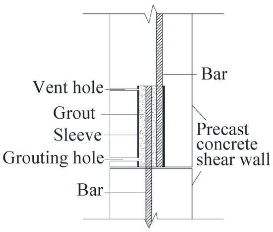
Figure 3.
Sketch of grouted sleeve lapping connector.
Although the grouted sleeve lapping connector offers the advantages of a large sleeve inner diameter and low sleeve manufacturing cost, it is unknown whether the tensile capacity of the grouted sleeve lapping connector is larger or smaller than that of the grouted splice connector and if there is a difference between the failure modes of the two connectors. Thus, it is meaningful and essential to conduct experimental research to study the differences in tensile capacity and failure modes between the two connectors.
There are many significant typical mechanical properties of grouted splice connectors, such as the mechanism of force transfer [28], the bond stress distribution along the embedded length [13], and the confining mechanism [18]. In-depth studies of these mechanical properties have been conducted for the grouted splice connector [29,30,31,32,33,34], which significantly promotes the application of this connector. Similarly, research on the mechanical properties of the grouted sleeve lapping connector must be conducted to provide a theoretical basis for its popularization. A previous study on the grouted sleeve lapping connector focused on its feasibility and working mechanism, and two equations were developed to calculate the average lapping bond stress and the critical lap length using linear regression [27]. Many principal mechanical properties—the load transfer mechanism, the force state on the cross section, and the bond stress distribution along the lapped bars—were not investigated.
To fill in the gaps that were left by the previous study, 16 grouted sleeve lapping connectors and three grouted splice connectors were tested under monotonic conditions. Since the subject of this research is to study the mechanical behavior of the grouted sleeve lapping connector, the test on three grouted splice connectors can be considered as a reference, in which the purpose is to conduct a comprehensive analysis of the grouted sleeve lapping connector. The differences in the tensile capacity and the failure modes between the two connectors were studied, and the origin of these differences was explored. The mechanical properties of the grouted sleeve lapping connector were analyzed in terms of the bond stress distribution between the bar and the grout, the force state in the middle section, and the strain of the reinforcement bars and the sleeve. In addition, an approximate mechanical model was put forward to describe the mechanical properties of the grouted sleeve lapping connector.
2. Experimental Procedure
2.1. Description of Specimens
2.1.1. Grouted Sleeve Lapping Connector
Figure 4 shows the details of the grouted sleeve lapping connector specimens. The specimen comprised two lapped main bars and a grouted-filled sleeve, which was cut from a cylindrical standard steel pipe without any reprocessing. One main bar was spot-welded to the pipe and is, henceforth, referred to as the welded bar. The other main bar, which is referred to as the inserted bar, was placed close to the welded bar and the sleeve pipe-wall. The length of the overlap was the same as the length of the sleeve.
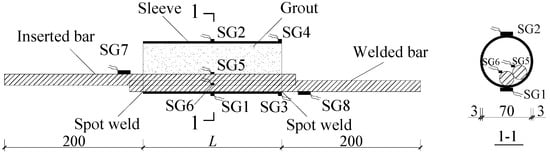
Figure 4.
Details of specimens and location of strain gauges (units: mm).
Being different from the grouted sleeve lapping connector shown in Figure 3, in which the inserted bar is not close to the welded bar, the two bars in this experimental study (as shown in Figure 4) are near to each other and both close to the sleeve pipe-wall. The purpose of this design was to test the mechanical properties of the grouted sleeve lapping connector under the worst-case scenario.
Steel pipes with internal diameters of 70 mm and thicknesses of 3 mm with a nominal yield strength of 335 N/mm2 were used to splice the bars. All of the bar diameters were 18 mm. The sleeve lengths, L, were 100, 150, 200, 250, and 300 mm. Each group of a particular lap length contained three or four identical specimens.
2.1.2. Grouted Splice Connector
Figure 5 is a schematic of the grouted splice connector specimens. The bars were placed in a line that passed through the central axis of the sleeve. The sleeve was the same as that in the grouted sleeve lapping connector and was cut from a cylindrical standard steel pipe with an inner diameter and thickness of 70 mm and 3 mm, respectively. The bar diameter was 18 mm. Three identical specimens with sleeve lengths of 200 mm were fabricated.
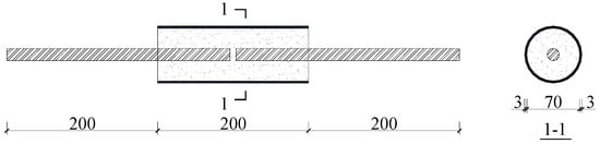
Figure 5.
Schematic of grouted splice connector (units: mm).
2.2. Material Properties
The specimens of grouted sleeve lapping connectors and grouted splice connectors had the same material properties. Control bars with a nominal yield strength of 400 N/mm2 were tested and the measured average yield strength and tensile strength were 469.2 MPa and 602.5 MPa, respectively. The flexural, compressive, and tensile strengths of the grout were 15.1 MPa, 71.2 MPa, and 6.0 MPa, respectively. The yield strength, tensile strength, and elastic modulus of the steel pipe were 363.8 MPa, 523.63 MPa, and 184.2 GPa, respectively.
2.3. Test Scheme and Setup
Prior to testing, strain gauges (SG) were installed on the grouted sleeve lapping connectors, as shown in Figure 4.
1. SG1 and SG2 were installed transversely at the midpoint of the sleeve length, and SG1 was placed closer to the overlapped bars than SG2,
2. SG3 and SG4 were installed at the bottom of the sleeve to measure the sleeve hoop strain, and SG3 was placed closer to the overlapped bars than SG4,
3. SG5 and SG6 were installed longitudinally midway along the length of the spliced bars inside the sleeve, and
4. SG7 and SG8 were installed on the spliced bars outside the sleeve, which was 20 mm away from the grout surface.
The fabrication of specimens is shown in Figure 6.
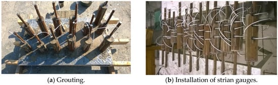
Figure 6.
Fabrication of specimens.
The specimens were loaded using a hydraulic actuator, as shown in Figure 7. The bars were pulled out at a constant rate of 2 kN/s until the load reached the bar yield strength of 450 MPa. Subsequently, the load was in a displacement control at a rate of 100 mm/min until the specimen failed.
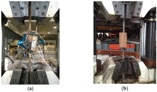
Figure 7.
Setup of the tensile test. (a) Grouted sleeve lapping connector. (b) Grouted splice connector.
3. Test Results
For the grouted sleeve lapping connector, the misalignment of the main bars generated secondary moments that resulted in the rotation of the sleeve and a slight bending of the bars outside the sleeve, as shown in Figure 8. It is well-known that bar kinking produces local and early failure of the bond between the bar and grout [19] and the results are conservative. If the specimen passes a test in which there is no restraint on rotation, the specimen will perform better under restrained rotation [35]. In addition, in the field, the connector is surrounded and constrained by the concrete and stirrups in the precast shear wall or column such that the deflection of the connector is impeded. However, further studies in which the connector is constrained to avoid deflection need to be conducted.
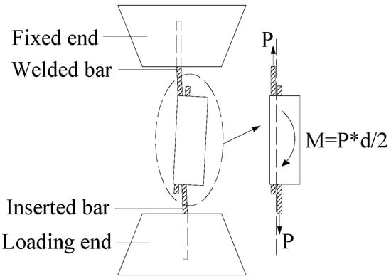
Figure 8.
Deflection of the grouted sleeve lapping connector after testing.
The ultimate tensile capacity (), the ultimate tensile strength (), and the failure mode of all the specimens are listed in Table 1.

Table 1.
Results of specimens under monotonic loading.
3.1. Strength Evaluation
It is evident from the test results in Table 1 that the tensile capacity of the specimens that failed by bar tensile fracture was close to that of the bare bar in tension.
According to ACI-318 [36] specifications, the tensile strength of a splice should be at least 125% of the nominal yield strength of the spliced bar. Therefore, the ratio of the tensile strength of the splice to the yield strength of the spliced bar, Rs, should satisfy: Rs ≥ 1.25. The strength ratings following this criterion are shown in Table 1. It is shown that the specimens of the grouted sleeve lapping connector with lap lengths greater than or equal to 150 mm satisfied the previously mentioned criterion.
3.2. Failure Mode
Figure 9 illustrates the typical failure modes of the specimens. The typical failure modes for the grouted sleeve lapping connectors were bar tensile fracture and bar-grout slip. All of the grouted splice connectors failed by the mode of grout-sleeve slip.
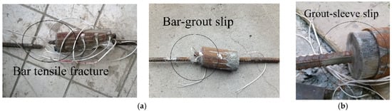
Figure 9.
Failure modes of specimens. (a) Grouted sleeve lapping connector. (b) Grouted splice connector.
The tensile capacity of the specimens was governed by the tensile capacity of the main bars, the bond capacity between the bar and the grout, and the bond capacity between the grout and the sleeve.
For the grouted sleeve lapping connectors of 150-4, 200-2, 200-3, the 250 series, and the 300 series, the lap length was long enough to provide a sufficient bond stress between the bar and the grout. Thus, the bond capacity between the bar and the grout for these specimens was larger than the tensile capacity of the main bars, which results in the failure mode of the bar fracture. The grouted sleeve lapping connectors of the 100 series, 150-1, 150-2, 150-3, and 200-1 had a short lap length, and the ultimate bond stress between the bar and the grout was not sufficient to prevent the bar from slipping out of the grout. Thus, these specimens failed the bar-grout slip. The grout-sleeve slip did not occur for the grouted sleeve lapping connectors.
For all of the grouted splice connectors, the ultimate bearing capacity depended on the bond strength between the grout and the sleeve. All of the specimens failed by the grout-sleeve slip as long as the load exceeded the ultimate bond between the grout and the sleeve.
3.3. Load-Displacement Curve
Figure 10a,b demonstrated the load-displacement responses of the grouted sleeve lapping connectors. For the specimens of the 100 series that failed by the mode of bar-grout slip, the displacement varied about linearly with the load increment initially and then failed suddenly when the load exceeded the tensile capacity of the specimen. Since the tensile strength of the specimens was smaller than the yield strength of the overlapped bars, the curve exhibited no plastic regime. Therefore, the specimens failed in a brittle manner.
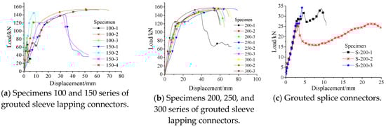
Figure 10.
Load-displacement curves.
Although the specimens 150-1, 150-2, 150-3, and 200-1 also failed by the mode of the bar-grout slip, the tensile strength of these specimens was larger than the yield strength of the bar. Thus, the bars were in the post-yielding state when the specimens failed, and their load-displacement curves exhibited yielding and hardening stages, which was different from the behavior of the specimens of the 100 series. Therefore, these specimens failed in a ductile manner.
Specimens of the 150-4, 200-2, 200-3, 250 series, and 300 series failed by bar tensile fracture and exhibited a ductile response. The load–displacement curves of these specimens that failed by the mode of bar fracture was basically the same as that of the bare bar. The curves exhibited an approximately elastic response at the initial stage. The stiffness gradually degraded as the rotation of the sleeve and the development of internal micro-cracks [14]. However, the magnitude of this change was insignificant. As the bar yielded, a large displacement was produced for a small load increment. The curve began to descend after the load exceeded the tensile capacity of the specimens.
The load-displacement curves of the grouted splice connectors are shown in Figure 10c. Since the ultimate tensile strength was smaller than the bar yield strength, all of the specimens failed in a brittle manner. For the specimens S-200-1, S-200-2, and S-200-3, the tensile load first increased to an initial peak and then decreased to a certain value. Subsequently, the tensile load increased to a second peak as the displacement increased. Lastly, the tensile load decreased suddenly, and the loading process ended. The curve can be explained by the following destruction mechanism: immediately after the load reached the first peak, the grout was completely pulled off at the middle section and split into two pieces. Subsequently, the load was carried by the bond between the separated grout and the sleeve until the grout was pulled out of the sleeve. The second peak corresponded to the maximum bond strength between the separated grout and the sleeve.
4. Comparison between Grouted Splice Connectors and Grouted Sleeve Lapping Connectors
4.1. Tensile Capacity
Table 2 shows the tensile capacity of the grouted splice connectors and grouted sleeve lapping connectors with the same bar anchorage length of 100 mm. When the inner surface of the sleeve was smooth and parameters other than the bar structural form were identical, the average tensile capacity of the grouted sleeve lapping connectors was 2.45 times that of the grouted splice connectors. This result showed that the lap of the bars enabled the grouted sleeve lapping connectors to provide much greater bearing capacity than the grouted splice connectors with aligned bars.
Table 2.
Comparison between the grouted splice connector and the grouted sleeve lapping connector.
This result can be explained by the difference in the load transfer between the two types of connectors. In the grouted splice connector, the tensile force was transferred from one bar to the other though two paths. In Path I, part of the tensile force was transferred through the grout to the sleeve wall by the bond, which is similar for the other bar [13,18]. In Path II, the remainder of the force was transferred through the surrounding grout to the other bar directly. The load transfer paths are shown in Figure 11.
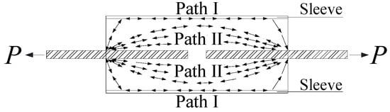
Figure 11.
Load transfer path of the grouted splice connector.
In addition to the same load transfer paths as the grouted splice connector, a third path (Path III) is available for the grouted sleeve lapping connector, in which part of the force is transferred though the grout between the bars directly. Path III is depicted in Figure 12, which shows the section passing through the centerline of the two bars. In this load transfer path, the two bars extruded each other, which creates a tendency for the two bars to move away from each other [37,38,39]. The expansion degree of the grout increased, and the radial confinement provided by the sleeve became stronger. The sleeve made a higher contribution for providing transverse confinement in the grouted sleeve lapping connector, which, in turn, increased the ultimate bearing capacity of the connector [40].
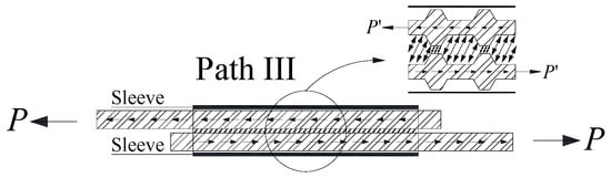
Figure 12.
Load transferred from one bar to the other directly in the grouted sleeve lapping connector.
4.2. Failure Mode
As shown in Table 2, the failure modes of the specimens of the grouted splice connectors and the grouted sleeve lapping connectors with the same bar anchorage length of 100 mm were the grout-sleeve slip and the bar-grout slip, respectively. The different structural forms of the bars resulted in these different failure modes.
It is well-known that the bond for deformed bars comprises three components: chemical adhesion, friction, and mechanical interlock between the concrete and the bar [41,42]. The sleeve of the grouted splice connector has a smooth inner pipe-wall and there is no mechanical interlock between the grout and the sleeve. Thus, the bond force between the grout and the sleeve consists of the chemical adhesion force () and the friction force ().
In light of the load-displacement curves of the grouted splice connectors (as shown in Figure 9c), we define the first load peak value as the rupture load (), and the second load peak value as the ultimate friction force (). Then, Equations (1) and (2) can be written as:
where denotes the ultimate tensile force of the grout at the middle cross section, denotes the ultimate chemical adhesion force between the separated grout and the sleeve, and denotes the ultimate friction force between the separated grout and the sleeve.
The values of and for the three specimens are shown in Table 3.
Table 3.
and for a grouted splice connector.
By establishing a force equilibrium at the middle of the grout and assuming a uniform tensile stress distribution for the grout at the cross section (Figure 13), it follows that:
where P is the load, is the resultant tensile stress of the grout, and is the resultant bond stress between the grout and the sleeve, which equals the chemical adhesion force () before the grout slips, and it is equivalent to the friction force () after the grout slips.
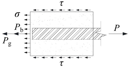
Figure 13.
Force equilibrium at the middle of the grout in a grouted splice connector.
Bar tensile fracture is the ideal failure mode for a connector. To guarantee that the grouted splice connector fails by the bar tensile fracture, the bond force between the grout and the sleeve () must be larger than , where is the ultimate tensile capacity of the bar and can be calculated by Equation (4). is the ultimate tensile force of the grout at the middle cross section and can be calculated by Equation (5) below.
where d is the bar diameter, is the ultimate tensile strength of the bar, is the inner diameter of the sleeve, and is the ultimate tensile strength of the grout.
By substituting the values of d, , and into Equations (4) and (5), the values of and can be obtained. Thus, the minimum value of can be computed as 130.15 kN. This result means that the bond force between the half grout and the sleeve needed to be larger than 130.15 kN to ensure that the grouted splice connector failed by the bar rupture. However, as shown in Table 3, the maximum of the chemical adhesion force () and the friction force () did not meet the requirement. Thus, certain construction measures, such as setting shear keys in the sleeve internal wall, are necessary to generate the mechanical interlock force and increase the bond force between the grout and sleeve in a grouted splice connector.
No grout-sleeve slip failure could occur in the grouted sleeve lapping connector. The two lapped main bars that passed through the entire sleeve were subjected to forces in the opposite directions. Since the grout could only slip out of the sleeve along with the bar, the grout could only slip after the bar slipped. However, by the time the bar could slip, the bond between the bar and the grout would have already failed, and the bar could not both pull the grout and slide out of the sleeve, even if the grout had been completely split in the cross section. Therefore, the grout sleeve lapping connector could not fail by bar-grout slip even though the interior surface of the sleeve was smooth.
5. Mechanical Analysis of Grouted Sleeve Lapping Connector
5.1. Bond Stress Distribution between the Bar and Grout
Figure 14 shows the mechanical equilibrium of the inserted bar in a grouted sleeve lapping connector. The resultant bond stress acting on the inserted bar by the grout from section A to B is denoted as and the resultant bond stress acting on the inserted bar by the grout from section B to C is denoted as . Neglecting the effect of the gap opening displacement [43], it follows that:
where is the tensile forces of the reinforcement bar, which was calculated by using the strains measured by SG5.
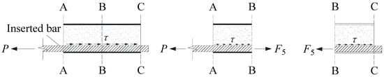
Figure 14.
Mechanical equilibrium of the inserted bar in the grouted sleeve lapping connector.
Figure 15 illustrates the ratios of and to loads of 25 kN, 50 kN, and the ultimate load (). As we can see from Figure 14, for all of the specimens under loads of 25 kN and 50 kN, the ratios of to the respective load were larger than 50%, whereas the ratios of to the respective load were smaller than 50%, which was in accord with the bond stress distribution variation law of the bond pull-out test [44] (as shown in Figure 16a,b). Even a very small load caused some slip, and a high bond stress developed near the loaded end. However, the upper part of the bar was left completely unstressed, as shown in Figure 16b. When a higher load was applied, the slip at the loaded end increased, and both the high bond stress and slip extended deeper into the specimen.
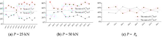
Figure 15.
Ratios of and to specific loads in the grouted sleeve lapping connector.
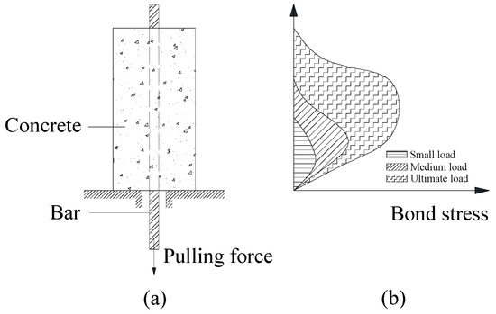
Figure 16.
Bond pullout test with bond stress distributions (reproduced from Reference [44]).
At the ultimate load, the ratios of to the respective load were generally near 50%. This result can be explained by Figure 16b. When the slip almost reached the unloaded end, and the maximum resistance had nearly been reached, the bond stress close to the unloaded end was almost equal to the loaded end, which resulted in being nearly equal to .
It can be concluded that the bond stress distribution around the inserted bar in the grouted sleeve lapping connector was similar to that around a single bar anchored in concrete.
5.2. Force State at the Middle Section
From the force equilibrium in the middle section of the grouted sleeve lapping connector (as shown in Figure 17), the following is found.
where P denotes the load and and denotes the tensile forces of the reinforcement bars, which can be calculated by using the strains measured by SG5 and SG6. denotes the tensile force of the sleeve, which is also the resultant shear stress acting on the sleeve wall. denotes the resultant tensile stress of the grout and denotes the resultant of and . Substituting the relevant data into Equation (8) yields the value of .
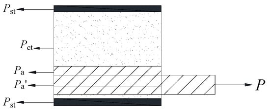
Figure 17.
Force equilibrium at the middle of the grouted sleeve lapping connector.
Figure 18 shows the relationship between P and for specimens with different lap lengths. For the specimens of the 150, 200, 250, and 300 series, the developments of the curves were similar and could be divided into three stages. In the first stage, i.e., section AB, was tensile and increased with the load. reached its maximum () when the load reached a certain value (). In the second stage, i.e., section BC, was still tensile, but it decreased as the load increased. At the moment that the load value reached , the value of decreased to 0. In the last stage, i.e., section CD, was compressive and increased with the load.
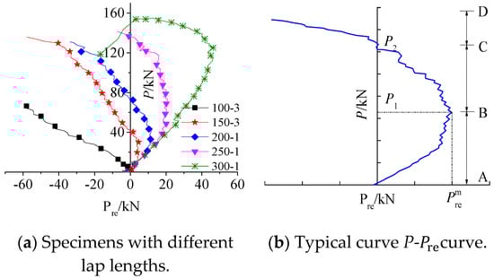
Figure 18.
Relationship between P and .
As we can see from Table 4, , and increased with the lap length. The increment in the lap length engaged more bar ribs in interlocking with the grout keys from the loading end to the middle section, such that a larger part of the load was borne by the bond between the bar and grout. Thus, for the same load, the longer was the lap length, the smaller was , and the larger was . Therefore, the maximum tensile value of (i.e., ) and the corresponding load () increased with the lap length.
Table 4.
Maximum of and corresponding P1 and P2.
According to Equation (6), was equal to P when was 0. The load transfer from the loading end to the middle section was slower when the lap length was longer. Therefore, it took more time for the value of to increase to the value of P as the loading rate was fixed. This showed that the duration of section AC where was tensile was longer. Accordingly, the value of was larger for the specimens with longer lap lengths.
5.3. Strain Analysis of Reinforcement Bars
The load-strain curves of the bars outside the sleeve (i.e., SG7 and SG8), the color of which is translucent, are shown in Figure 19. The load-strain curve of the control bar (i.e., the bare bar in tension), is also presented using a black curve with dark spots as a reference. The strain was tensile at all times and increased with the load during the elastic range in the control bar, whereas the strain gauges in the bars outside the sleeve indicated a compressive or tensile strain before the bar started yielding. This result was obtained because the gauges were located in the compressive or tensile region of the bended bar outside the sleeve.
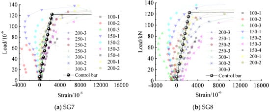
Figure 19.
Load-strain relationship for bars outside the sleeve in a grouted sleeve lapping connector.
The load–strain curves of the bars in the middle section of the sleeve (i.e., SG5 and SG6) are shown in Figure 20. For specimen 100-3, the development of the load–strain curve of SG6 differed considerably from that of SG5. As the sleeve deflected significantly, and the segment of the bar where SG6 was located bended, the tensile value of SG6 was larger than the strain value of the control bar under the same load.
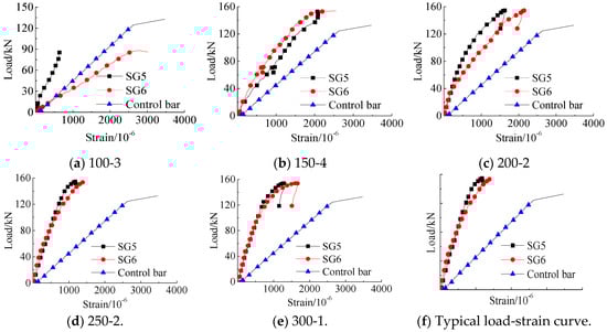
Figure 20.
Load-strain curves of SG5 and SG6 in a grouted sleeve lapping connector.
For specimens with lap lengths larger than 100 mm, the strain values of SG5 and SG6 were near each other under the same load, and these values were both smaller than the strain value of the control bar. This was because a considerable portion of the pulling force was borne by the bond force between the bar and grout from the loaded end to the middle section, and the tensile forces at the bar where SG5 and SG6 were located were smaller than the pulling force.
Typical load-strain curves of SG5 and SG6 are shown in Figure 20f. The slope of the curves clearly decreased as the load increased, which was different from the curve of the control bar for which the slope remained unchanged as the load increased during the elastic stage. As the load increased, the bond failure between the bar and grout developed from the loaded end to the free end, and the rate of the internal force of the bar at the middle section accelerated. Thus, the rate of the strain of SG5 and SG6 increased and the slope of the curves decreased.
5.4. Strain Analysis of the Sleeve
The strain states in the transverse direction for the sleeve were caused by the axial and radial forces acting on the sleeve. According to the generalized Hooke’s law, the axial compressive force produced the hoop tensile strain, whereas the axial tensile force caused the hoop compressive strain. The radial force triggered the transverse expansion of the sleeve, which resulted in a tensile strain in the sleeve in the transverse direction.
5.4.1. Analysis of Hoop Compressive Strain for the Sleeve
Figure 21a shows the load-strain curves of SG1 (as shown in Figure 4) installed on specimens with lap lengths of 100 mm, 200 mm, and 300 mm. Generally, the curves could be classified into three similar regimes (as shown in Figure 21b). In the first stage, the strain was compressive and increased with the load. The compressive strain reached a maximum () when the load reached a certain value (). In the second stage, the strain was still compressive, but decreased as the load increased. At the moment that the load reached , the strain decreased to 0. In the last stage, the strain was tensile and increased with the load until a maximum was reached.
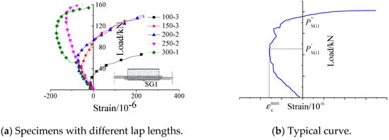
Figure 21.
Load-strain curves of SG1 in a grouted sleeve lapping connector.
The ultimate compressive strain values of SG1 (i.e., ), and the corresponding loads () are shown in Figure 22. To reduce the scatter caused by the heterogeneity of the grout and the sleeve deflection, the average values of specimens with the same lap length were used. As the lap length increased, the average ultimate compressive strain value of SG1 and the corresponding average load increased. As we can see from Figure 18a, at the same load, the longer the lap length was, the larger and the axial tensile force of the sleeve were. Thus, the axial tensile stress of the sleeve wall increased with respect to the lap length, which led to a larger hoop compressive strain in the sleeve. In addition, an increment in the lap length decreased the radial stress and the expansion degree of the sleeve in the transverse direction [27], which resulted in a smaller hoop tensile strain in the sleeve. Therefore, the longer the sleeve was, the larger the ultimate hoop compressive strain of the sleeve and the corresponding load were.
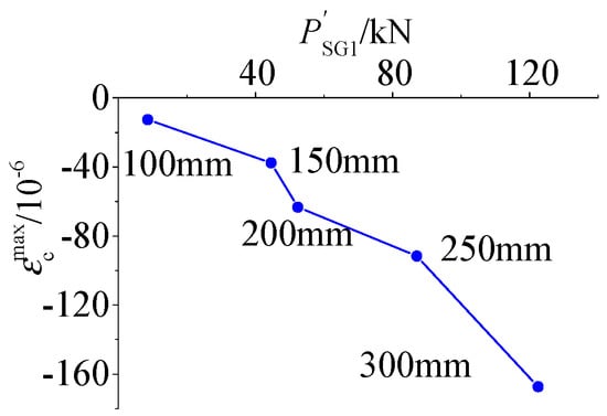
Figure 22.
Ultimate compressive strain values of SG1 () and corresponding loads ().
5.4.2. Comparison of Sleeve Hoop Strains
Figure 23 shows the load-strain curves for SG1, SG2, SG3, and SG4 for typical specimens with different lap lengths. At the late loading stage, the tensile strain of SG4 (SG3) was higher than that of SG2 (SG1) in almost all of the specimens. This means the hoop tensile strains that were measured by the tensile strain gauges installed at the end of the sleeve were higher than that at the mid-sleeve, which shows that the expansion degree of the grout at the end of the sleeve was greater than at the mid-sleeve. This is because the grout at the end of the sleeve was sliding or had the tendency to slide out of the sleeve at the late loading stage, which resulted in a greater expansion degree of the grout at the end of the sleeve.
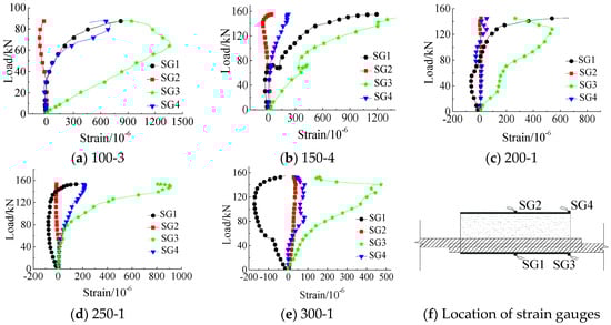
Figure 23.
Typical load-strain curves of SG1, SG2, SG3, and SG4 in a grouted sleeve lapping connector.
The rotation of the sleeve (as shown in Figure 8) led to the kinked bar pressing the sleeve wall and to the transverse expansion degree of the sleeve close to the bars, which was larger than that of the sleeve far from the bars. Since SG3 was placed closer to the bars than SG4, the tensile strain of SG3 was larger than that of SG4 for almost all of the specimens, which shows that the hoop tensile strain in the sleeve close to the overlapped bars was larger than the overlapped bars at the end of the sleeve.
5.5. Approximate Mechanical Model
Figure 24 shows an approximate mechanical model of the grouted sleeve lapping connector. In the model, the two bars cling to each other, and the line connecting their centers passes though the center of the sleeve. Assuming the tensile stress of the grout has a triangular distribution at the ultimate load, the equilibrium equation can be written per unit length as follows.
where S is the effective length, known as the unit length. are the stresses of the sleeve wall far from the overlapped bars and close to the overlapped bars, respectively, where the values of are obtained by multiplying the elastic modulus (E) by the strain of SG2 () and the strain of SG1 (), respectively. denotes the cross-sectional area of the sleeve wall and is equal to the product of and . t is the thickness of the sleeve. is the nominal tensile strength of the grout. is the sleeve internal diameter. d is the bar diameter and is the radial stress acting on the grout that is exerted by the bar ribs.
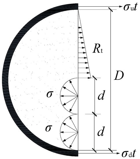
Figure 24.
Mechanical model of a grouted sleeve lapping connector.
Figure 25 shows the bond stress distribution on the bar surface. Assuming that the bond stress, , is uniformly distributed on the bar surface, Equation (10) is as follows.
where is the pulling force, is the bond stress, and is the lap length.
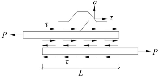
Figure 25.
Distribution of bond stress along the steel bar.
Assuming that the radial stress () equals the longitude, bond stress () yields:
Combining Equations (9)–(11) yields Equation (12).
To evaluate the reliability of the mechanical model, the maximum pulling force (), the corresponding stresses and , and other relevant data for the specimens that failed by bar-grout bond failure were substituted into Equation (10), and the calculated lap length (Lcal) was compared to the actual lap length (L). The results are shown in Table 5. It was found that the average calculated lap length () was near the actual lap length (L), which indicated that the approximate mechanical model was highly reliable.
Table 5.
Comparison between calculated lap length, Lcal, and actual lap length, L.
6. Conclusions
Experimental studies were performed on 16 grouted sleeve lapping connectors and three grouted splice connectors under tensile loading. The differences in the tensile capacity and failure modes between the grouted splice connector and the grouted sleeve lapping connector were studied. Analysis of the mechanical properties of the grouted sleeve lapping connector was conducted. The following conclusions can be drawn based on this research.
(1) When the inner surface of the sleeve was smooth and all of the parameters other than the bar structural form were the same, the tensile capacity of the grouted sleeve lapping connector was 2.45 times that of the grouted splice connector, which was explained in terms of the different load transfer mechanisms of the two connectors.
(2) Different bar configurations resulted in different failure modes for the connectors. All of the grouted sleeve lapping connectors with lapped bars failed by a bar tensile fracture or bar-grout slip, whereas the only failure mode of the grouted splice connectors with aligned bars was a grout-sleeve failure. Specific construction measures must be taken to generate a mechanical interlock force to improve the bond force between the grout and the sleeve in the grouted splice connector.
(3) The bond stress distribution around the inserted bar in the grouted sleeve lapping connector was similar to that around a single bar anchored in concrete.
(4) For the grouted sleeve lapping connectors, the slopes of the load-displacement curves of strain gauges installed at the middle bar inside the sleeve decreased as the load increased. As the lap length increased, the ultimate hoop compressive strain of the sleeve and the corresponding load increased.
(5) An approximate mechanical model was put forward to describe the mechanical properties of the grouted sleeve lapping connector and was proved to be highly reliable.
Studying the feasibility of a grouted sleeve lapping connector under a cycling load is a future research direction. It is also necessary to test the seismic behavior of precast shear walls with vertical reinforcements that are spliced by grouted sleeve lapping connectors to evaluate the operating performance of grouted sleeve lapping connectors when used in structures.
Author Contributions
Q.Y. proposed the method, conceived the experiments, and wrote the paper. J.S. performed the experiments and analyzed the data. Z.X. conceived and designed the experiments, analyzed the data, and wrote the paper. L.L., Z.Z., and S.Y. revised the paper.
Funding
The National Natural Science Foundation of China (Grant number: 51322803) supported this research.
Conflicts of Interest
The authors declare no conflict of interest.
Nomenclature
| ultimate tensile capacity of the specimen (kN) | tensile force of the sleeve (kN) | ||
| ultimate tensile strength of the specimen (N/mm2) | resultant tensile stress of the grout (kN) | ||
| strength ratio | resultant of and (kN) | ||
| ultimate tensile force of the grout at the middle cross section (kN) | tensile load corresponding to the maximum tensile value of (kN) | ||
| rupture load of the specimen (kN) | tensile load when equals 0 (kN) | ||
| ultimate friction force of the specimen (kN) | unit length (mm) | ||
| ultimate chemical adhesion force between the separated grout and the sleeve (kN) | stress of the sleeve wall far from the overlapped bars (N/mm2) | ||
| ultimate friction force between the separated grout and the sleeve (kN) | stress of the sleeve wall close to the overlapped bars (N/mm2) | ||
| tensile load (kN) | elastic modulus of the bar (N/mm2) | ||
| resultant tensile stress of the grout (kN) | cross-sectional area of the sleeve (mm2) | ||
| resultant bond stress between the grout and the sleeve (kN) | strain of the strain gauge installed transversely at the middle of the sleeve | ||
| ultimate tensile capacity of the bar (kN) | thickness of the sleeve (mm) | ||
| ultimate tensile force of the grout at the middle cross section (kN) | radial stress acting on the grout that is exerted by the bar ribs (N/mm2) | ||
| bar diameter (mm) | nominal tensile strength of the grout (N/mm2) | ||
| ultimate tensile strength of the bar (N/mm2) | bond stress between the bar and the grout (N/mm2) | ||
| inner diameter of the sleeve (mm) | lap length of the bars (mm) | ||
| ultimate tensile strength of the grout (N/mm2) | calculated lap length (mm) | ||
| tensile force of the bar (kN) | average calculated lap length (mm) |
References
- Park, R. A Perspective of the Seismic Design of Precast Concrete Structures in New-Zealand. PCI J. 1995, 40, 40–60. [Google Scholar] [CrossRef]
- Yee, A.A. Structural and economic benefits of precast/prestressed concrete construction. PCI J. 2001, 46, 34–42. [Google Scholar] [CrossRef]
- Li, L.Z.; Liu, X.; Yu, J.T.; Lu, Z.D.; Su, M.N.; Liao, J.H.; Xia, M. Experimental study on seismic performance of post-fire reinforced concrete frames. Eng. Struct. 2019, 179, 161–173. [Google Scholar] [CrossRef]
- Li, L.Z.; Bai, Y.; Yu, K.Q.; Yu, J.T.; Lu, Z.D. Reinforced high-strength engineered cementations composite (ECC) columns under eccentric compression: Experiment and theoretical model. Eng. Struct. 2019, 198, 109541. [Google Scholar] [CrossRef]
- Albrigo, J.; Ricker, E.D.; Colarusso, L.J. Reinforcing Bar Splice and System for Forming Precast Concrete Members and Structures. U.S. Patent 5,468,524, 21 November 1995. [Google Scholar]
- Yee, A.A. Splice Sleeve for Reinforcing Bars. U.S. Patent 3,540,763, 27 June 1968. [Google Scholar]
- Precast Prestressed Concrete Institute. New precast prestressed system saves money in Hawaii hotel. PCI J. 1973, 18, 10–13. [Google Scholar]
- Lu, Z.; Wang, Z.; Li, J.; Huang, B. Studies on seismic performance of precast concrete columns with grouted splice sleeve. Appl. Sci. 2017, 7, 571. [Google Scholar] [CrossRef]
- Parks, J.E.; Papulak, T.; Pantelides, C.P. Acoustic emission monitoring of grouted splice sleeve connectors and reinforced precast concrete bridge assemblies. Constr. Build. Mater. 2016, 122, 537–547. [Google Scholar] [CrossRef]
- Li, H.; Chen, W.; Hao, H. Dynamic response of precast concrete beam with wet connection subjected to impact loads. Eng. Struct. 2019, 191, 247–263. [Google Scholar] [CrossRef]
- Tullini, N.; Minghini, F. Grouted sleeve connections used in precast reinforced concrete construction—Experimental investigation of a column-to-column joint. Eng. Struct. 2016, 127, 784–803. [Google Scholar] [CrossRef]
- Ling, J.H.; Abd. Rahman, A.B.; Ibrahim, I.S.; Hamid, Z.A. An Experimental Study of Welded Bar Sleeve Wall Panel Connection under Tensile, Shear, and Flexural Loads. Int. J. Concr. Struct. Mater. 2017, 11, 525–540. [Google Scholar] [CrossRef]
- Hosseini, S.J.A.; Abd. Rahman, A.B.; Osman, M.H.; Saim, A.; Adnan, A. Bond behavior of spirally confined splice of deformed bars in grout. Constr. Build. Mater. 2015, 80, 180–194. [Google Scholar] [CrossRef]
- Ling, J.H.; Abd. Rahman, A.B.; Ibrahim, I.S.; Hamid, Z.A. Tensile capacity of grouted splice sleeves. Eng. Struct. 2016, 111, 285–296. [Google Scholar] [CrossRef]
- Einea, A.; Yamane, T.; Tadros, M.K. Grout-filled pipe splices for precast concrete construction. PCI J. 1995, 40, 82–93. [Google Scholar] [CrossRef]
- Ministry of Housing and Urban-Rural Development of the People’s Republic of China. Technical Specification for Grout Sleeve Splicing of Rebar (JGJ 355-2015); China Architecture & Building Press: Beijing, China, 2015. (In Chinese)
- Zheng, Y.; Guo, Z.; Guan, D.; Zhang, X. Parametric study on a novel grouted rolling pipe splice for precast concrete construction. Eng. Struct. 2018, 166, 452–463. [Google Scholar] [CrossRef]
- Zheng, Y.; Guo, Z.; Liu, J.; Chen, X.; Xiao, Q. Performance and confining mechanism of grouted deformed pipe splice under tensile load. Adv. Sturct. Eng. 2016, 19, 86–103. [Google Scholar] [CrossRef]
- Lin, F.; Wu, X. Effect of sleeve length on deformation properties of grouted splices. Gradevinar 2017, 69, 537–546. [Google Scholar]
- Zheng, Y.; Guo, Z.; Zhang, X. Effect of grout properties on bond behavior of grouted pipe splice. KSCE J. Civ. Eng. 2018, 22, 2951–2960. [Google Scholar] [CrossRef]
- Ling, J.H.; Abd. Rahman, A.B.; Ibrahim, I.S.; Abdul Hamid, Z. Behaviour of grouted pipe splice under incremental tensile load. Constr. Build. Mater. 2012, 33, 90–98. [Google Scholar] [CrossRef]
- Alias, A.; Zubir, M.A.; Shahid, K.A.; RAhman, A.B.A. Structural performance of grouted sleeve connectors with and without transverse reinforcement for precast concrete structure. Procedia Eng. 2013, 53, 116–123. [Google Scholar] [CrossRef]
- Ling, J.H.; Abd. Rahman, A.B.; Ibrahim, I.S. Feasibility study of grouted splice connector under tensile load. Constr. Build. Mater. 2014, 50, 530–539. [Google Scholar] [CrossRef]
- Han, W.; Zhao, Z.; Qian, J. Global experimental response of a three-story, full-scale precast concrete shear wall structure with reinforcing bars spliced by grouted couplers. PCI J. 2019, 64, 65–80. [Google Scholar]
- Henin, E.; Morcous, G. Non-proprietary bar splice sleeve for precast concrete construction. Eng. Struct. 2015, 83, 154–162. [Google Scholar] [CrossRef]
- Lu, Z.; Huang, J.; Li, Y.; Dai, S.; Peng, Z.; Liu, X.; Zhang, M. Mechanical behaviour of grouted sleeve splice under uniaxial tensile loading. Eng. Struct. 2019, 186, 421–435. [Google Scholar] [CrossRef]
- Yu, Q.; Xu, Z. Experimental study of grouted sleeve lapping connector under tensile load. Gradevinar 2017, 69, 453–465. [Google Scholar]
- Hosseini, S.J.A.; Rahman, A.B.A. Effects of spiral confinement to the bond behavior of deformed reinforcement bars subjected to axial tension. Eng. Struct. 2016, 112, 1–13. [Google Scholar] [CrossRef]
- Hosseini, S.J.A.; Abd. Rahman, A.B. Analysis of spiral reinforcement in grouted pipe splice connectors. Gradevinar 2013, 65, 537–546. [Google Scholar]
- Kuang, Z.; Zheng, G. Computational and experimental mechanical modelling of a composite grouted splice sleeve connector system. Materials 2018, 11, 306. [Google Scholar] [CrossRef]
- Lin, F.; Wu, X. Mechanical performance and stress-Strain relationships for grouted splices under tensile and cyclic loadings. Int. J. Concr. Struct. Mater. 2016, 10, 435–450. [Google Scholar] [CrossRef]
- Liu, H.; Han, Q.; Bai, Y.; Xu, C.; Du, X. Connection performance of restrained deformed grouted sleeve splice. Adv. Struct. Eng. 2018, 21, 488–499. [Google Scholar] [CrossRef]
- Sayadi, A.A.; Abd. Rahman, A.B.; Sayadi, A.; Bahmani, M.; Shahryari, L. Effective of elastic and inelastic zone on behavior of glass fiber reinforced polymer splice sleeve. Constr. Build. Mater. 2015, 80, 38–47. [Google Scholar] [CrossRef]
- Sayadi, A.A.; Rahman, A.B.A.; Jumaat, M.Z.B.; Johnson Alengaram, U.; Ahmad, S. The relationship between interlocking mechanism and bond strength in elastic and inelastic segment of splice sleeve. Constr. Build. Mater. 2014, 55, 227–237. [Google Scholar] [CrossRef]
- Coogler, K.L.; Harries, K.A.; Gallick, M. Experimental study of offset mechanical lap splice behavior. ACI Struct. J. 2008, 105, 478–487. [Google Scholar]
- American Concrete Institute. Building Code Requirements for Structural Concrete and Commentary (ACI 318M-11); American Concrete Institute: Farmington Hills, MI, USA, 2011. [Google Scholar]
- Tastani, S.P.; Brokalaki, E.; Panatazopoulou, S.J. State of bond along lap splices. J. Struct. Eng. 2015, 141. [Google Scholar] [CrossRef]
- Aly, R. Stress along tensile lap-spliced fibre reinforced polymer reinforcing bars in concrete. Can. J. Civ. Eng. 2007, 34, 1149–1158. [Google Scholar] [CrossRef]
- Asadian, A.; Eslami, A.; Farghaly, A.S.; Benmokrane, B. Lap-Splice Length of Bundled Glass Fiber-Reinforced Polymer Bars in Unconfined Concrete. ACI Struct. J. 2019, 116, 287–299. [Google Scholar] [CrossRef]
- Robins, P.; Standish, I.G. The influence of lateral pressure upon anchorage bond. Mag. Concr. Res. 1984, 36, 195–202. [Google Scholar] [CrossRef]
- Lutz, L.A.; Peter, G. Mechanics of bond and slip of deformed bars in concrete. ACI J. 1967, 64, 711–721. [Google Scholar]
- Lei, J.; Shi-ping, Y.; Ke, D. Analysis of the interface bond property between the concrete and steel bar under textile reinforced concrete confinement. Constr. Build. Mater. 2019, 224, 447–454. [Google Scholar]
- Wu, D.; Liang, S.; Guo, Z.; Zhu, X. Flexural capacity calculation approach for precast grouted shear wall influenced by joint interface displacements. Adv. Mater. Sci. Eng. 2015, 2015. [Google Scholar] [CrossRef]
- Ferguson, P.M.; Breen, J.E.; Jirsa, J.O. Reinforced Concrete Fundamentals, 5th ed.; John Wiley & Sons, Inc.: New York, NY, USA, 1988; pp. 310–312. [Google Scholar]
© 2019 by the authors. Licensee MDPI, Basel, Switzerland. This article is an open access article distributed under the terms and conditions of the Creative Commons Attribution (CC BY) license (http://creativecommons.org/licenses/by/4.0/).