Featured Application
It is useful and easy to predict performance of an electromagnetic launcher.
Abstract
An electromagnetic launcher (EML) is used to generate high launching velocities. The basic governing equation of the propulsion force of an EML is that the propulsion force is directly proportional to current and inductance gradient. is the inductance gradient that refers to the increase or decrease in the inductance with the length of rails. The inductance gradient is easily calculated because it is a function of the rail shape and frequency. However, current () flowing in an EML is calculated by the series resistor, inductor, and capacitor (RLC) equation of the equivalent circuit. Here, is not constant and increases as the projectile muzzles. Owing to the increase in inductance, the current () and voltage () vary depending on the projectile position. Therefore, inductance, current, and voltage should be exactly obtained to calculate the exact current at a specific time. This study deals with analytical performance prediction using the relation EML propulsion force with real-time current, which is based on an increase in resistance and inductance at a specific time. To validate this approach, the results of the current waves are compared via numerical analyses and experiments. Using this prediction method, it is possible to determine and optimize the rail shape and length from the capacitor bank and vice versa.
1. Introduction
In recent times, electromagnetic launching systems have been adopted to substitute existing launch systems. For example, electromagnetic launchers (EMLs) or railguns have been developed to install battleships by the US Navy and the Chinese Navy since 1995 and 2011, respectively [1,2,3]. Moreover, the French-German Research Institute has developed the PEGASUS Launcher, having a 10- Mega Joule (MJ) pulse power system, to increase efficiency and high muzzle velocity [4,5,6]. The most attractive advantage of an EML is the ability to obtain higher projectile velocities than conventional gunpowder-type guns.
Another application of an electromagnetic launching system is the electromagnetic aircraft launch system (EMALS). This is currently being developed by General Atomics and the US Navy. The main advantage of this is that it can accelerate an aircraft more smoothly, thereby incurring less stress on the aircraft and carrier. Further, EMALS has less weight, cost, and maintenance requirements than a steam catapult [7]. Similar to EMALS, the magnetic system for UAV carriers has been developed. The advantages of this system include a short runway, reduced risk of pilot casualty, and reduced cost of having an airborne device [8].
Another application is that of a heavy projectile launcher. The direct launch of payloads into orbit is impossible. However, it would be possible to launch rugged payloads, such as fuel, water, and others. There are two main advantage of this technology: it is possible to achieve high muzzle velocities and it is easy to force control with a pulse power system [9,10,11,12].
Furthermore, the propulsion force of an electromagnetic launcher is the Lorentz force; this force is applied electric propulsion (EP). EP is termed ion or plasma thrusters. It has a low thrust level compared to that of electromagnetic launchers. EP has significant advantages for in space propulsion for smaller objects and longer durations. EP is independent of a propellant, posing a risk of explosion with a large energy density [13,14,15,16].
Since the 1950s, studies and research on EMLs have been conducted and a few useful equations to predict their performance have been established. A useful equation is given below, which is schematically illustrated in Figure 1.
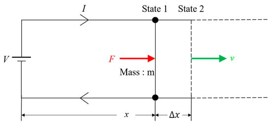
Figure 1.
Electromagnetic launcher (EML) schematic view.
This equation draws from the conservation of energy requirement
where is calculated by generated on a projectile of mass and displacement () from state 1 to state 2.
Further, the increase in inductive energy is calculated using inductance gradient () determined from “Kerrisk ,” which is a function of the shape of the rail and current () [17,18].
The energy delivered to the EML circuit is
The voltage form of Faraday’s law is given as . The voltage is then given by
Equations (2)–(6) indicate that the propulsion force of an EML (Equation (1)) generated on the projectile can be calculated from the inductance gradient and current at a specific time [19].
Using this equation, considerable analytical research was conducted to predict the performance of an electromagnetic launcher or other [20,21,22,23,24]. However, these analytical analyses did not consider variations in specific time current with an increase in resistance and inductance. Moreover, this equation applies to active electromagnetic launcher armor that utilizes the Lorentz force in a manner similar to an electromagnetic launcher [25].
To identify the propulsion Lorentz force at a time instant, current () should then be determined. To acquire current () at a time instant, the series resistor, inductor, and capacitor (RLC) equivalent circuit of an EML was developed, as shown in Figure 2, following the initial conditions of the capacitor bank and EML. The original step response of the series RLC circuit is given by the following equation.
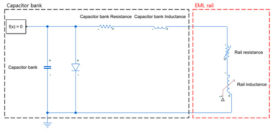
Figure 2.
EML equivalent circuit.
As the projectile is accelerated and approaches the muzzle, resistance and inductance of the rail are increased, owing to the resistance and inductance gradient. Further, the current value is varied. To conduct a more accurate analysis, the initial condition of the capacitor bank and EML circuit, resistance, and inductance should be considered and updated in Equation (7). The updated equation is given in Equation (8).
According to this equation, the performance of the EML can be predicted using the flow chart shown in Figure 3. By incorporating resistance and inductance gradients, system resistance and inductance were updated in this study to precisely predict the performance of a projectile.
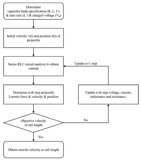
Figure 3.
EML performance prediction flow chart.
2. Analytical Performance Prediction of EML
To analytically predict the performance of the EML, the capacitor and bank specifications are determined. Further, the length and size of rails are determined, as listed in Table 1. Each capacitor specification is 480 V and 6800 µF. One hundred capacitors are connected in parallel, and the equivalent specification of the capacitor bank is 480 V and 0.68 F; the rail size is 750 mm (l) × 30 mm (h) × 5 mm (w), as shown in Figure 4. These electrical properties of the capacitor bank and rails are listed in Table 2.

Table 1.
Electromagnetic launcher (EML) specification.
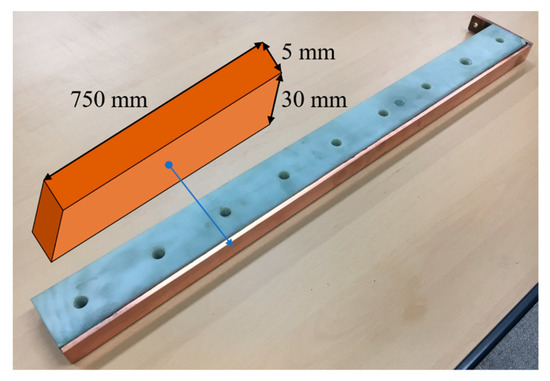
Figure 4.
EML rail dimensions.

Table 2.
Electrical properties of EML.
By using these properties and Equation 8, the performance is analytically predicted. The prediction sequence is as follows:
- Set the initial conditions—charged capacitor voltage, projectile loaded position, and initial velocity.
- Find Lorentz force from initial condition.
- Find velocity () and displacement () from [26]. Here, ‘m’ is projectile mass.
- Update resistance () and inductance () according to projectile displacement .
- Find current ( and voltage () through a series equivalent RLC circuit analysis after from a previous time. The determined current and voltage will be the initial conditions for the next step.
- Go to 2nd step until the objective velocity or rail length are attained.
According to this sequence, the muzzle velocity and current with the 750 mm length of rail mentioned earlier of this chapter is determined using MATLAB R2019a and Simulink Simscape Electrical. In the 3rd step, the friction force is approximately 0.56 times the propulsion force of an EML (0.56) [19].
The muzzle velocity calculated using this approach is 252.485 m/s. Velocity as time and current as time are shown Figure 5. The reflection of inductance and resistance gradient is an extremely important point to predict EML performance.
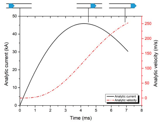
Figure 5.
Current and projectile velocity profiles obtained using MATLAB R2019a analysis.
3. EML Numerical Analysis with 750 mm Length Rail
By using LS-DYNA EM, a performance prediction may be conducted under the same conditions as those of the previous analytical prediction. The analysis model and boundary conditions are shown in Figure 6. The rails selected in this study are made of copper, and the projectile is Al 6061-T6. The outer surfaces of copper rails are fully fixed, and the Al 6061-T6 projectile traces solely the launching direction, i.e., from the breech to the muzzle. Further, to generate Lorentz force, an impose current wave is required, which is obtained along the path of the current flow established through the analysis model.
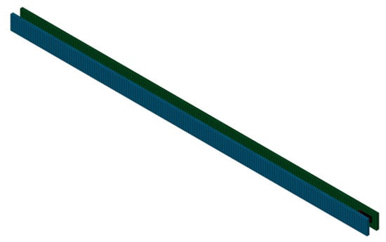
Figure 6.
EML numerical analysis model using LS-DYNA EM.
The biggest advantage of LS-DYNA EM is the reflection of varying shape, such as a moving projectile in the EML. Generally, other software cannot support real-time deformation or variation in shape [27].
From LS-DYNA EM, the current and velocity profile are obtained, as shown in Figure 7. The projectile velocity is 250.786 m/s. These results are similar to those of the analytical performance prediction.
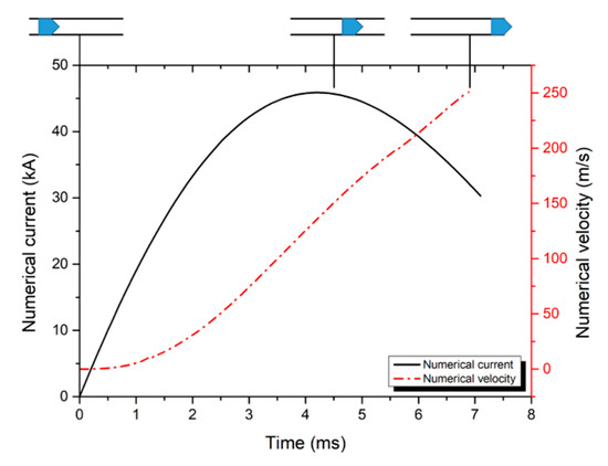
Figure 7.
Current and projectile velocity profiles obtained using LS DYNA EM.
4. EML Experiment with 750 mm Length Rail
An EML system was developed, as shown in Figure 8. The specifications and dimensions are listed in Table 1 and Table 2, as mentioned in Section 2 and Section 3. The 6 g Al 6061-T6 projectile is loaded between the rails, 25 mm from the breech. Then, the capacitor bank is charged to 300 V and discharged instantaneously.
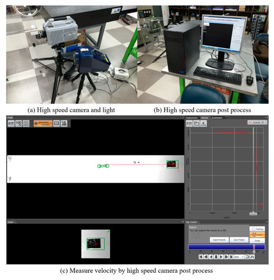
Figure 8.
(a) High-speed camera (Photron FASTCAM SA-X2). (b) Post processor. (c) Measuring projectile muzzle velocity.
The measured muzzle velocity is 250 m/s using a Photron FASTCAM SA-X2 high-speed camera, as shown in Figure 8.
Further, the current flow is measured using a Rogowski coil, as shown in Figure 9, and the flow is shown in Figure 10. The measured muzzle velocity and current flow from a high-speed camera and Rogowski coil will be compared with the analytical velocity and current flow to validate the analytical method.
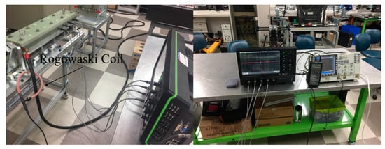
Figure 9.
Rogowski coil to measure the current of the EML.
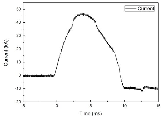
Figure 10.
Measured current of the EML using Rogowski coil.
5. Results
The results of the muzzle velocity and current flow obtained using analytical, numerical, and experimental predictions are shown in Figure 11.
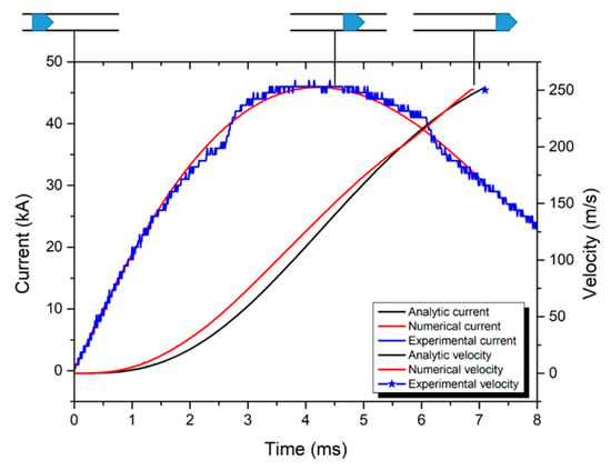
Figure 11.
Current and projectile velocity profiles by analytical, numerical, and experimental methods.
Although this analytical approach can provide simple results, which are projectile displacement, velocity, current, and voltage, it does not require a long time and advanced computational resources such as finite element methods. From Figure 11, the following conclusions can be drawn.
- The current values from the analytical method and experiment results are similar.
- The velocity values from the analytical method and numerical analysis results are also similar.
- Every case of muzzle velocity is similar.
6. Conclusions
This study suggests that reflection of the projectile position in terms of resistance and inductance gradients is important for a precise analytical approach in rails. Moreover, it will be useful to determine muzzle velocity for a fixed rail length. According to this process, an EML performance can be easily predicted via an analytical method. The advantages of this analytical method are that it is more time and cost effective than finite element methods such as LS-DYNA EM. Similar to this approach, the maximum muzzle velocity can be obtained using an optimized rail length, or can determine the optimized rail and projectile shape using the capacitor bank specifications.
Author Contributions
Conceptualization, methodology, software (MATLAB R2019a, LS-DYNA EM), experiment, operation, visualization, validation, writing—original draft preparation, and writing—review and editing, H.-K.K; supervision, project administration and funding acquisition, Y.H.M., B.-S.K. and J.K.
Funding
This work was supported by the National Research Foundation of Korea (NRF) grant funded by the Korea government (MSIT) through the Engineering Research Center (No. 2019R1A5A6099595) and the Basic Science Research Program (No. NRF-2017R1D1A3B03034265).
Conflicts of Interest
The authors declare no conflict of interest.
Nomenclature
| Inductance | H | |
| Inductance gradient | H/m | |
| Current | A | |
| Resistance | Ω | |
| Voltage | V |
References
- Hogg, J. Keynote address: History of the U.S. navy railgun program. IEEE Trans. Plasma Sci. 2017, 45, 1069–1070. [Google Scholar] [CrossRef]
- Ma, W.; Lu, J.; Liu, Y. Research progress of electromagnetic launch technology. IEEE Trans. Plasma Sci. 2019, 47, 2197–2205. [Google Scholar] [CrossRef]
- Doerry, N.; Amy, J.; Krolick, C. History and the status of electric ship propulsion, integrated power systems, and future trends in the U.S. Navy. Proc. IEEE 2015, 103, 2243–2251. [Google Scholar] [CrossRef]
- Hundertmark, S.; Vincent, G.; Simicic, D. Developing a Launch Package for the PEGASUS Launcher. IEEE Trans. Plasma Sci. 2017, 45, 1234–1238. [Google Scholar] [CrossRef]
- Hundertmark, S.; Vincent, G.; Simicic, D.; Schneider, M. Increasing Launch Efficiency with the PEGASUS Launcher. IEEE Trans. Plasma Sci. 2017, 45, 1607–1613. [Google Scholar] [CrossRef]
- Hundertmark, S.; Simicic, D.; Vincent, G. Acceleration of Aluminum Booster Projectiles with PEGASUS. IEEE Trans. Plasma Sci. 2015, 43, 1147–1151. [Google Scholar] [CrossRef]
- Neely, J.; Rashkin, L.; Cook, M.; Wilson, D.; Glover, S. Evaluation of power flow control for an all-electric warship power system with pulsed load applications. In Proceedings of the 2016 IEEE Applied Power Electronics Conference and Exposition (APEC), Long Beach, CA, USA, 20–24 March 2016; pp. 3537–3544. [Google Scholar]
- Ładyżyńska-Kozdraś, E.; Sibilska-Mroziewicz, A.; Sławomir, C.; Krzysztof, F.; Sibilski, K.; Wróblewski, W. Take-off and landing magnetic system for UAV carriers. J. Mar. Eng. Technol. 2017, 16, 298–304. [Google Scholar] [CrossRef][Green Version]
- Kozlov, A.V.; Kotov, A.V.; Polistchook, V.P.; Shurupov, A.V.; Shurupov, M.A. Electromagnetic launcher for heavy projectiles. J. Phys. Conf. Ser. 2017, 927, 012027. [Google Scholar] [CrossRef]
- Chunyan, L.; Baoquan, K. Research on Electromagnetic Force of Large Thrust Force PMLSM Used in Space Electromagnetic Launcher. IEEE Trans. Plasma Sci. 2013, 41, 1209–1213. [Google Scholar] [CrossRef]
- McNab, I.R. Launch to space with an electromagnetic railgun. IEEE Trans. Plasma Sci. 2003, 39, 205–304. [Google Scholar] [CrossRef]
- Fair, H.D. Advances in Electromagnetic Launch Science and Technology and Its Applications. IEEE Trans. Plasma Sci. 2009, 45, 225–230. [Google Scholar] [CrossRef]
- Electric propulsion for satellites and spacecraft: Established technologies and novel approaches. Plasma Sources Sci. Technol. 2016, 25, 033002. [CrossRef]
- Prospects and physical mechanisms for photonic space propulsion. Nat. Photonics 2018, 12, 649–657. [CrossRef]
- Choueiri, E.Y. A critical history of electric propulsion: The first 50 years (1906–1956). J. Propul. Power 2004, 20, 193–203. [Google Scholar] [CrossRef]
- Levchenko, I.; Keidar, M.; Cantrell, J.; Wu, Y.L.; Kuninaka, H.; Bazaka, K.; Xu, S. Explore space using swarms of tiny satellites. Nature 2018, 562, 185–187. [Google Scholar] [CrossRef]
- Piątek, Z.; Baron, B.; Szczegielniak, T.; Kusiak, D.; Pasierbek, A. Inductance of a Long Two-Rectangular Busbar Single-Phase Line. Available online: http://pe.org.pl/articles/2013/6/57.pdf (accessed on 28 September 2019).
- Keshtkar, A.; Maleki, T.; Kalantarnia, A.; Keshtkar, A. Determination of Optimum Rails Dimensions in Railgun by Lagrange’s Equations. In Proceedings of the 2008 14th Symposium on Electromagnetic Launch Technology, Victoria, BC, Canada, 10–13 June 2008. [Google Scholar]
- Marshall, R.A.; Ying, W. Railguns: Their Science and Technology; China Machine Press: Beijing, China, 2004. [Google Scholar]
- Yin, Q.; Zhang, H.; Li, H.J.; Yang, Y.X. Analysis of in-bore magnetic field in C-shaped armature railguns. Def. Technol. 2019, 15, 83–88. [Google Scholar] [CrossRef]
- Račkauskas, J.; Kačianauskas, R.; Schneider, M. Investigation of armature-rail interaction in linear electromagnetic launcher. J. Vibroeng. 2018, 20, 1234–1239. [Google Scholar] [CrossRef]
- Ceylan, D.; Güdelek, M.U.; Keysan, O. Armature Shape Optimization of an Electromagnetic Launcher Including Contact Resistance. IEEE Trans. Plasma Sci. 2018, 46, 3619–3627. [Google Scholar] [CrossRef]
- Ghassemi, M.; Barsi, Y.M. Effect of liquid film (indium) on thermal and electromagnetic distribution of an electromagnetic launcher with new armature. IEEE Trans. Plasma Sci. 2005, 41, 408–413. [Google Scholar] [CrossRef]
- Shirong, Y.; Ying, W.; Shanbao, C.; Guohua, P.; Xuqiong, L.; Wei, W. A novel type rail-coil hybrid electromagnetic launcher. IEEE Trans. Plasma Sci. 2005, 41, 266–267. [Google Scholar] [CrossRef]
- Wang, H.; Huang, Y.; Li, R.; Duan, H.; Jin, H. Structural Optimization of Electromagnetic Launcher in Active Electromagnetic Armor. IEEE Trans. Plasma Sci. 2011, 39, 487–491. [Google Scholar] [CrossRef]
- Kim, S.H.; An, S.; Lee, B.; Lee, Y.H.; Yang, K.S. Modeling and circuit analysis of an electromagnetic launcher system for transient current waveforms. In Proceedings of the 2014 17th International Symposium on Electromagnetic Launch Technology, San Diego, CA, USA, 7–11 July 2014. [Google Scholar]
- Kim, H.K.; Kang, B.S.; Kim, J. Muzzle velocity estimation of an electromagnetic launcher using B-dot probe. Int. J. Appl. Electromagn. Mech. 2019. [Google Scholar] [CrossRef]
© 2019 by the authors. Licensee MDPI, Basel, Switzerland. This article is an open access article distributed under the terms and conditions of the Creative Commons Attribution (CC BY) license (http://creativecommons.org/licenses/by/4.0/).