Abstract
An emerging requirement in multimedia applications over the Internet is the provisioning of synchronized play out of multimedia streams on all the ultimate receivers. Most multimedia applications use real-time transport protocol/real-time control protocol (RTP/RTCP) to transport multimedia data over the internet. Internet Protocol (IP) network incurs a loss and/or delay of media packets resulting in distortions at receivers that can be perceived by the user. These distortions need to be removed before data is presented to the end user. To handle such issues inter-stream and intra-stream synchronization algorithms were developed by the researcher using RTP/RTCP protocols. These schemes could not work under multicasting environment properly. In this paper, we have presented an algorithm based on RTP/RTCP protocol that achieved synchronized playout of multimedia data under multicasting environment. The proposed scheme offers a modification in RTCP and usage of the Network Time Protocol (NTP) as a source of the common clock to achieve synchronized playout of multimedia data on multiple devices at the same time. We have implemented and tested our algorithm in Ericson Research Corporate Unit, Lulea, Sweden. Implementation results show that the proposed algorithm delivered accurately synchronized playout of multimedia data under all the possible scenarios defined in the experimental setup.
1. Introduction
The most significant change in the last decade was the growth of the internet as the main communication medium between individuals. This has influenced humanity significantly and has opened different possibilities to innovate and to improve the quality of existing services as well as value added service provisioning. Among other enhancements, multimedia applications are also evolved and have gained a considerable place. There is considerable research in motion and event detection in multimedia applications like [1,2,3,4] as well as in feature extraction and analysis among multiple tasks in a multimedia application [5]. In the evolution of multimedia applications in Internet Protocol (IP) networks, synchronization has been a big issue [6].
Multicast synchronization refers to the simultaneous playout of all multimedia streams over all the intended receivers. For example, if there are many loudspeakers in a building, the media stream is required to be played out in such a way that all speakers playout simultaneously and the voice of speakers does not interfere each other. Most of the multimedia applications use Real-Time Transport Protocol/Real-Time Control Protocol (RTP/RTCP) to transport multimedia data over the internet [7]. IP network introduces loss and/or delay of media packets resulting in synchronization error at receivers that can be perceived by the user. These distortions need to be removed before data is presented to the end user. Inter-stream and intra-stream synchronization [6] in multimedia applications have been addressed by many researchers using RTP/RTCP protocols but none of them addresses synchronization of multimedia data under multicast environment. In this paper, we have presented an algorithm based on RTP/RTCP protocol that achieved synchronized playout of multimedia streams on all ultimate receivers over User Datagram Protocol/Internet Protocol (UDP/IP).
2. Related Work
Computer networks were designed to connect computers on different locations so that they can share data and resources with each other. Initially, most of the data carried on networks were textual data but today in the current world, with the rise of multimedia and network technologies, multimedia data has become an indispensable feature on the Internet. Animations, voice and video clips (both real-time and streaming) have become more and more popular over the Internet [8]. Using the internet as a platform for multimedia communication gave birth to multimedia networking products like IP telephony, IP-TV, video conferencing, etc. In future, possibly people would enjoy more improved multimedia products in distance learning, distributed work groups, and in other real-time contextual services [8]. One fundamental characteristic of packet switched network is the delay incurred during packet delivery. Other issues include packet loss, packet corruption, and duplication and delayed arrivals. The current architecture of IP networks does not guarantee the Quality of Service (QoS) in terms of bandwidth, delay and packet loss [6].
In multimedia applications, the source packetizes the information and then transmit it over the network. These packets might get delayed, lost, the order changed and could be corrupted before received by the receiver. The receiver receives the packets and tries to reconstruct the original signal. Multimedia (audio/video) data is expected to be played back continuously at the sampling rate. It was also synchronized with other streams that require the timing relations to be maintained through the network. However, the packet switched networks distorts the timing relations between the packets. The natural behavior of IP networks demands some new transport protocols to take care of timing information and other multimedia data characteristics. Research in this area helped to reach the invention of media layer protocol named RTP/RTCP [8] to address properly the issues raised above.
Currently, the key standard for media transport in IP networks is the RTP protocol framework. It provides transport and control services for multimedia data (audio/video) over IP networks. These services include timing information, source identification, quality feedback, synchronization, and membership management, etc. [9,10]. As stated earlier that most of the multimedia applications use RTP/RTCP protocol to transport media data over the internet.
RTP [7] is a real-time end-to-end transport layer protocol, mostly used upon UDP. RTP does not guarantee the delivery of packets in a timely manner, nor does it do the packet sequencing. RTP provides payload type identification, source identification, sequence numbering, and time stamping required most of the multimedia applications. The accompanying RTCP provides feedback on the quality of the data delivery and information about session participants [11]. An RTP session usually is composed of an RTP port number (UDP port), an RTCP port number (consecutive UDP port) and the participant’s IP address. The RTP data transport is augmented by a control protocol (RTCP) [7], which provides the RTP session participants feedback on the quality of the data distribution. RTCP provides QoS provisioning, congestion control and estimating the session lengths. QoS monitoring information is directly embedded in the RTCP packet to handle these issues occurred with the original data during transmission over the network.
The other most important protocol used in multimedia data transportation is Network Time Protocol (NTP) that is widely used to synchronize computer clocks on the Internet [12]. NTPv4 is widely used to synchronize system clocks among a set of distributed time servers and clients. The purpose of the NTP protocol is to convey timekeeping information from these primary servers to secondary time servers and clients via both private networks and the public Internet. Synchronization in multimedia systems actually refers to the temporal relations between media objects in a multimedia system [6]. In multimedia applications, when packets are transmitted from the sender, they undergo different delays on their way to the destination and hence lose their timing relations. Such a misalignment in temporal relation is one of the reasons to cause synchronization error. To handle these errors, three kinds of synchronization have been presented in [6,13] and are discussed below.
2.1. Intra-Stream Synchronization
It refers to the time relationship between various presentations units of one time-dependent media object [6].
To understand intra stream synchronization, let us consider the Figure 1. The media packets are sent in a continuous stream with the constant inter-packet spacing. Due to IP network behavior, the delay between packets is no more constant when they are received as shown in Figure 2. If packets are played out as they are received, the receiver will have to wait for the random amount of time to playout the next packet. Thus the output will be a bad quality of voice/video. Playout buffering delay is imposed on the packets to compensate for jitter. Packets are held in the playout buffer for some time to process the delayed packets. Thus the final playout stream has uniform inter-packet spacing.
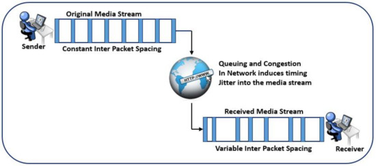
Figure 1.
Disruption of inter-packet timing during Network Transit.
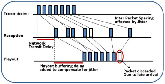
Figure 2.
Network jitter affects reception time and is corrected in the playout buffer.
If a packet arrives after its playout time has elapsed, it will be discarded as the encircled packet in Figure 2 arrived late and hence could not be played out. The amount of buffering delay depends upon the application and the network condition to avoid such packet losses. Similarly, if the packet arrives and finds that playout buffer is full, it will be dropped. There is no standard algorithm for calculating the jitter delay. It is fully dependent on the type of application and the network condition [10].
2.2. Inter-Stream Synchronization
In this scheme, the multimedia system is composed of two or more media streams (audio and video) and their playback must be temporally coordinated [14]. Retrieval of objects must precede so as not only to ensure continuity of playback of each of its constituent media streams but also preserves the temporal relationships among them [15]. For example, a video conference is composed of two media streams i.e., audio and video that needs to be synchronized in such a way that lips movement matches with speech (usually termed as lip synchronization) of the active person.
Audio and video data is carried out in separate streams and each stream is transported via a separate RTP session. They are normally delivered separately because audio and video packets are treated differently in the network. When streams are transported separately on to the network, packets come across different queues in the network, and hence undergo different lengths of delays. Also, jitter buffer delay can cause the misalignment in timing. Usually, the latencies involved in the video frames are more than that of audio frames. Thus, the streams are to be realigned before presenting to the actual receiver.
2.3. Visual Lips Movements
It refers the visual lips movements of a speaker must match the sound of the spoken words. If the video and audio displayed at the receiving endpoint are not at the same time then this misalignment between audio and video is referred to as skew. Without ensuring lip sync, audio often plays ahead of video, because the latencies involved in processing and sending video frames are greater than the latencies for audio [16].
The realignment of two streams is not possible with the information contained in RTP data packets. There should be a mechanism that indicates which of the two streams are to be synchronized. Secondly, time stamping is also required to correlate the two streams. Both of these pieces of information are transported in RTCP packets. RTCP-SR (RTCP-Sender Report) packets carry the NTP timestamp. RTCP-SDES (RTCP-Source Description) packets contain CNAME (Canonical Name) value that uniquely identifies the source and can be used to correlate the streams. In [16] intra-stream synchronization was achieved by considering the audio stream as a master stream and to delay the video stream as necessary to achieve LIP sync. The work described in [17] shown a client-driven approach for synchronizing multimedia data for packet-based video streaming.
3. Problem Statement
An emerging requirement in the multimedia applications over the internet is the provisioning of the synchronized playout of real-time media streams. Nowadays many proposals of intra and inter-stream synchronization algorithms for different scenarios exist but there are very few proposals for group synchronization, such as [17,18,19,20] have been implemented. All of them are receiver-based and, except the one in [17,19] that uses RTP and sender-based solution, the others did not use a standard protocol and define specific control messages to interchange between sources and receivers. Most of the multimedia applications use RTP/RTCP protocol to transport media data over the internet [21]. IP network introduces loss and/or delay of media packets resulting in distortions (i.e., synchronization error) at receivers that can be perceived by the user. These distortions need to be removed before data is presented to the end user. There have been two main types of synchronization, i.e., intra stream synchronization, and inter-stream synchronization. There are lots of proposals to implement inter-stream and intra-stream synchronization in multimedia applications by using RTP/RTCP [22] but to the best of our knowledge, none of them addresses group synchronization issue.
In this paper we have designed two use cases and implemented them in Ericson Network Research Center Lulea, Sweden to address the subjected issue of synchronizing multimedia data streams under multicasting environment. The two use cases are as under.
3.1. Use Case 1
The first use case is if a user would like to play audio and video on different devices, e.g., audio in headset and video on the TV. Both audio and video should be played-out synchronously regardless of the fact that they are being played out on different devices. The scenario is shown below in Figure 3a.
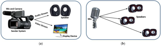
Figure 3.
Problem Statement use cases: (a) Use case 1; (b) use case 2.
3.2. Use Case 2
In the second use case, we have a number of audio receivers connected to loudspeakers located in the same room. The audio on the speakers should be played out at the same time so that the voice of one speaker could not interfere with the others as shown in Figure 3b.
3.3. Problem Scenarios
In order to understand the problem clearly, let us consider a simple example. The scenario consists of one sender, two receivers, and the single data stream is being transmitted from a sender to receivers as shown in Figure 4.
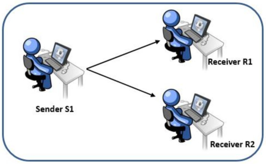
Figure 4.
Topology with one sender and two receivers.
Receivers R1 and R2 received packet P1 from sender S1, calculate its playout time and put it in the jitter buffer. Jitter buffer holds the packet till its playout time has arrived. This wait is enforced to remove the jitter and provide the smooth playout as shown in Figure 5a–c.
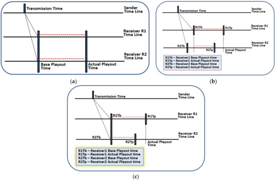
Figure 5.
Timeline diagrams showing transmitted and playout time. (a) Time line of base and actual playout time of two receivers (R1, R2); (b) Difference of packet reception at R1 and R2 due to receivers locations; (c) Timeline showing Synchronizing base playout time of R1 and R2.
In Figure 5a both receivers have same base playout time (packet received time is same), but usually, this does not happen in real time applications because the propagation delay varies. To calculate the playout time, receiver adds local playout delay and jitter buffer delay to the base playout time.
In Figure 5b both receivers have the same value for the delay at receiver (local playout delay + jitter buffer delay). However, this is not valid in the case of real-time applications because each receiver has its own processing speed. The local delay, in this case, varies due to the variation of network delays, jitter, and buffer delay among different receivers.
In Figure 5c the actual playout time calculated by both receivers R1 and R2 is the same. This is very unlikely to happen as even if two packets travel through the same path in an IP network but their transmission delay will be different in most of the cases due to the general behavior of IP networks. If the destinations R1 and R2 are far apart, the probability of variations in delay increases. Other factors like clock skew and buffer delays at receivers make it difficult to achieve synchronized playout. Therefore, there is a clear need to design an algorithm to handle synchronized playout of multimedia data on all the participating receivers.
In all three different cases the playout is smooth, i.e., receivers are synchronized with the source. This kind of synchronization is local synchronization. In this paper, we have developed a system that guaranteed the result similar to Figure 5a where both receivers are playing back at the same time.
4. Proposed Solution
4.1. Sender-Based Solution
Normally the receiver application calculates the playout time for multimedia data streams. The playout time calculation mostly results in different values at different receivers since it is calculated locally on each receiver. To get a common playout time at all receivers, we decided to determine the playout time for all the receivers at a single place in spite of being calculated at each receiver. Thus in our solution, the normal behavior of the sender and receiver is bypassed and the playout time is calculated at sender side nor at the receiver side.
To select the sender for calculating the playout time of the participating receivers, these steps are followed:
- The sender is accessible by all the receivers and can communicate the playout time to all the intended receivers. Also, the receivers can easily exchange the control information with the sender.
- The sender remains available throughout the session while receivers can join and leave the session at any time during the proceedings. If the sender leaves then there will be nothing to playout and thus no playout time needed.
In our proposed solution, to handle playout time, following constraints must be addressed:
- Determine the playout time at the source of the media stream.
- Enable the receivers to meet the suggested playout time.
- Provide a reference clock.
Figure 6 shows the timeline view of the solution. As it is observable that both the receivers receive packets at different time instances R1Tr and R2Tr. However, their playout time is same. This playout time is suggested by the sender. In this case receiver, R2 received packet earlier than receiver R1. To play the packet at the same playout time, the receiver R2 had to buffer the packet for a longer time than the receiver R1.
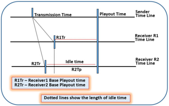
Figure 6.
Timeline diagram shows the effect of our solution.
4.2. Proposed Design Requirements
Following are the explicit requirements for the proposed solution:
- All receivers and senders share a common clock (wall clock).
- In order to determine the actual playout time, the sender must know the network condition (i.e., all receivers are connected properly).
- The sender needs to know the buffering status of the receivers.
- The sender sends playout time to the receivers and has the functionality to receive and interpret the additional information stated in points 2 and 3 from receivers.
- Points 2, 3 and 4 require some additional fields in the data or control packets.
- In order to achieve group synchronization, we used NTP [4] as a source of a common clock.
All the symbols used in mathematical equations and their definition can be found in Table 1.

Table 1.
Table of abbreviations.
4.2.1. Impact of the Common Reference Clock
The core of our solution is the perfect distribution of common reference clock. Let us consider if the clock distribution is not perfect then in such a case our solution is likely to be unsuccessful to give the desired output. The playout time provided by the sender is according to the common reference clock. The receiver calculates the playout time for the data packets using sender’s “packet sent time” value. If clocks of receivers and senders mismatch, a receiver can play stream asynchronously.
Let us consider the two simple cases to elaborate the possible problem.
- If the receiver’s clock is behind the sender’s clock, it can play the stream late as if it is a delayed stream. If the difference has a larger value then the receiver may run out of buffer space to buffer the packets for a long time.
- If the receiver’s clock is ahead of the sender’s clock then data packet’s playout time value obtained by the receiver may be the value that has already been elapsed.
4.2.2. Network Delay from Sender to Each Receiver
The sender must know the distance between the receivers from the sender. Definitely, each receiver will have a different distance from the sender and different network condition between sender to receivers. As sender calculated the single value of playout for all the receivers so it needs to have an idea of the network connecting each receiver.
4.2.3. One-Way Delay
One-way delay (OWD) is the time taken by the packet to arrive from sender to receiver. It gives knowledge of network congestion level to the sender. According to our solution, the receiver will send the received time of a data packet to the sender and sender will use the sent time of that data packet to calculate the one-way delay (dow) as:
To calculate OWD, we consider reference clock. In our solution, if the reference clock is absent, the packet’s received time noticed by the receiver will be according to its local clock which may not be the same as that of the sender’s clock. Thus, with this information sender’s calculation (Equation (1)) may not end up inaccurate results. Thus time values used in Equation (1) are supposed to be according to the reference clock.
4.2.4. Idle Time
The sender needs to know that how long a packet has to stay in the playout buffer of the receiver. When a receiver receives the packet, it puts it in the playout buffer where the packet stays until its playout time arrives. If a packet arrives later than its playout time (delayed), it is treated in a different way depending upon the application and the media being transmitted.
Receivers calculate this idle time using following equation.
We can elaborate this formula in another way as:
We use RTCP-APP packets to send information from receivers to senders and vice versa. Adding new fields to RTCP SR and RR packets will change the current protocol stack implementation.
Sender calculates playout time, packs it in APP packet and sends it to the receiver(s).
4.2.5. The Calculation of Playout Time at Sender Includes Two Parameters
- System Time (Send time of SR packet)—(tsr).
- Playout-delay offset (doff).
4.2.6. System Time
Sender APP packet contains the playout time that refers to the corresponding SR packet. RTCP-SR packet’s NTP timestamp field contains the time when this packet was sent in NTP timestamp format. System time parameter refers to RTCP-SR NTP timestamp field (according to the common reference clock). tsr is the time when RTCP-SR is prepared and is contained in SR packet’s NTP timestamp field. APP packet is prepared right after SR packet at time tapp. tsr and tapp are not same as shown in the Figure 7. App packet contains the sender’s calculated playout time. As we know this playout time corresponds to the NTP timestamp of the SR packet so tsr is used as System time for the calculation of playout time as stated in Equation (4).
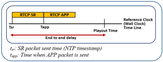
Figure 7.
A timeline overview of the solution.
4.2.7. Playout Delay Offset
Playout-delay offset refers to the time taken for a packet to be transmitted from sender till it is presented to the playout device. It includes network delay, machine processing delay and the queuing delay at receiver.
Sender takes system time (sent time of SR packet) and adds playout delay offset to it to generate playout time as:
Delay offset value remains same for all packets and receivers. The only sender is authorized to change this value if desired. Here one thing is very important to understand; RTCP packets are same for all receivers thus all receivers will receive the same value of system time (sent time of SR packet) and Playout time contained in sender’s APP packet.
4.2.8. Data Packets Playout Time Calculation and Synchronization
As we know APP packet contains the playout time of the corresponding SR packet. Due to the presence of reference clock, it is very easy to extract the delay offset value from RTCP packet and then uses it to calculate the playout time of the data packets. Following are the three steps to calculate the playout time of the data packet.
- Calculate the sent time of the data packet according to the reference clock.
- Extract the playout delay offset from the RTCP provided information.
- Add playout delay offset to the sent time of the data packet.
Playout time element in Equation (5) is same as calculated by Equation (4) earlier. As stated earlier, all the receivers receive the same RTCP packet from the sender, so they have the same value of playout offset. Thus, for a particular data packet, each receiver will have the same playout time as calculated by Equation (7) in the following subsection.
4.2.9. Sent Time of RTP Data Packet in System Time Clock Units
Data packet’s RTP timestamp is the instance when the packet was sampled. The NTP equivalent of this RTP timestamp can be calculated by correlating it with SR packet’s media timestamp and NTP timestamp. Let us consider Figure 8 to understand this.
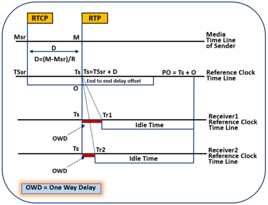
Figure 8.
A detailed overview of the proposed system.
Receiver observes the mapping between the media clock and reference clock as assigned by the sender. The mapping is conveyed in the periodic RTCP-SR packets. The nominal clock rate of media clock is known to both the sender and receiver by payload format. The receiver can easily calculate the reference clock capture time, once it has received an RTCP-SR packet. As shown in Figure 8. Reference clock capture time Ts for RTP packet can be calculated as:
- Mts is the media timestamp of the data packet.
- Msr is the media timestamp in last received RTCP SR packet.
- TSsr is the corresponding reference clock (NTP) timestamp.
- Rmts is nominal media timestamp clock rate (media clock ticks per second).
4.2.10. Calculation of Playout Time for Data Packets
In Figure 8 there are two receivers, both are having the same playout time although the packet received time is different but received time does not matter as the actual playout time calculation is based on sent time and the end to end delay offset. Sent time and delay offset are same for all the receivers. The varying values are received time, one-way delay and idle time. The variation of received time and one-way delay is compensated by the idle time.
4.2.11. Additional Information Container
We designed new APP packets for both sender and receiver. The App packet sent by sender carries playout time in NTP timestamp format. The structure of the packet is shown in Figure 9.
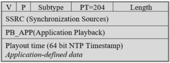
Figure 9.
RTCP-APP: Application-defined RTCP packet, to carry Playout time from the sender.
On the other hand, receivers reply back to the sender with the following parameters as part of their feedback,
- Reception time of the packet reported in highest extended sequence number.
- Idle time.
Received time is 64-bit fields in NTP timestamp format. Idle time is 32 bit signed integer to carry the time (ms) in our case. The receiver side packet description is shown in Figure 10.
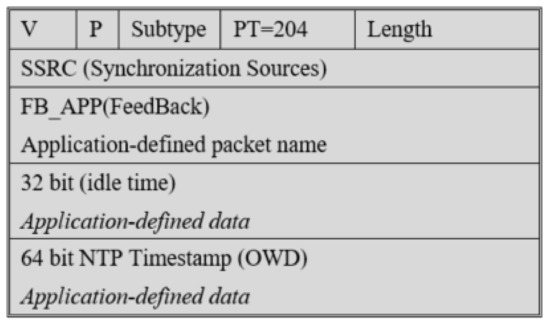
Figure 10.
RTCP-APP: Application-defined RTCP packet, to carry feedback from the receiver to sender.
5. Implementation Setup and Results Discussion
We used an RTP/RTCP library owned by Ericsson Research Corporate Unit, Lulea, Sweden and enhanced it as per our research requirements. This library was developed using Visual Studio 6.0 and protocol stack was developed using C but it has a C++ interface as well. It also includes an open source POSIX threading library to provide support for multithreading.
Following parameters have been set in our implementation. We tested our protocol in a real scenario over Ericson Research Wide Area Network (WAN). We modified RTP-based mbone tools for video and audio stream respectively. Both the audio and video streams were kept separated in the source application. The parameters of the setup are shown in Table 2.
Table 2.
Implementation of setup parameters.
We have tested our algorithm by defining four different scenarios:
- Scenario 1: Same playout time for all receivers.
- Scenario 2: One-way delay calculated at the sender.
- Scenario 3: Sender view of idle time under normal circumstances.
- Scenario 4: Fluctuation in delay offset and idle time.
5.1. Scenario 1: Same Playout Time for All Receivers
In Figure 11, the straight line showing that the packet was played out at the same time by all receivers. Some packets were received at slightly different time instance as compared to the others as encircled in Figure 11, but the playout time is not affected by this variation because the calculation of playout time depends upon the senders provided end to end delay offset and the sent time. The distance between sent time and playout time remains same for all receivers irrespective of the received time.
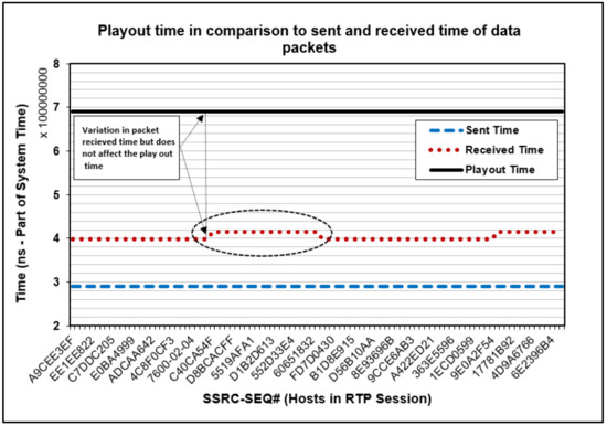
Figure 11.
Common/same playout time for all receivers.
5.2. Scenario 2: One-Way Delay Calculated at the Sender
One-way delay is calculated by the sender when it receives the feedback packets from receivers. One-way delay gives sender, the idea of network congestion level and helps in adjusting the playout time. This scenario actually demonstrates the one-way delay value calculated at the sender. Figure 12, shows that the one-way delay remains very consistent (i.e., OWD is mostly 109 ms and 110 ms). However, at two points, we can see large values of up to 125 ms. these two packets were delayed may be due to the functionality of nano sleep [18] that we used to impose network delay. The variation in network delay will result in variation in one way delay values calculated at the sender. One-way delay plays important role in the calculation of playout time. For instance, if some particular receiver is facing network congestion, it will consistently result in the very large value of one-way delay. This will intimate sender to take some action either to adjust the playout time or to slow down the packet sending rate.
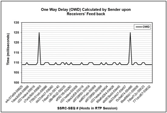
Figure 12.
One-way delay (OWD) calculated at sender side using feedback from the receivers.
5.3. Scenario 3: Sender View of Idle Time under Normal Circumstances
Idle time is calculated by the receivers. This is the time that a packet remained in the buffer while waiting for its playout time to arrive. Receivers send this value in RTCP-APP packets to the sender. The sender uses idle time value to estimate the local buffer condition of the receivers. Idle time value also plays important role in the calculation/adjustment of playout time. The sender has a pool of feedback values sent by 100 receivers. We did not change any of the settings during the execution to analyze the idle time under ideal conditions.
Figure 13, represents idle time against the one-way delay. One-way delay reflects that how early or late a packet was received. If the packet is received earlier, it will have a less one-way delay and vice versa. In case of idle time, an early receipt of the packet means longer idle time. Hence lesser the OWD, larger would be the idle time and similarly the other way round. To understand the idle time, we have encircled the area where a packet was received well earlier than rest of the packets. This packet had to stay for longer time in the playout buffer. Longer time in the playout buffer is represented by a larger value of idle time. If a packet is to be played out at the same time at all receivers, the earlier or late arrival of the packet is compensated by varying the idle time.
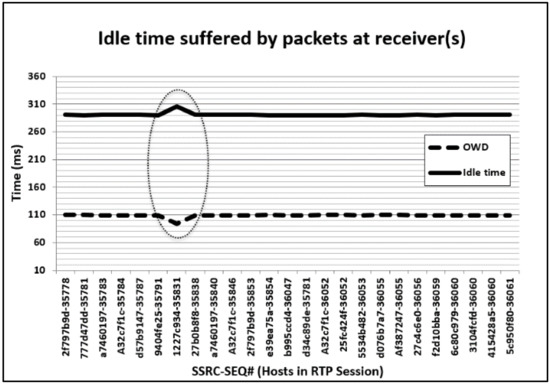
Figure 13.
Idle time vs. one-way delay (OWD).
5.4. Scenario 4: Fluctuation in Delay Offset and Idle Time
The special change made in this scenario is that the end-to-end delay offset does not remain constant during the whole period of execution. Sender shuffles the offset between 100, 200 and 300 at runtime. Figure 14, represents idle time against varying values of an end to end delay offset. Before having a look at the graph, it is important to know that why there is a need to change the end to end delay offset at runtime? The encircled area of the graph indicates the negative value of idle time. Negative idle time can only be possible if the packet is being received later than its playout time. In such a case if the receiver(s) are suffering from lots of delayed packets due to some reason, the sender can increase the value of playout offset to compensate the delayed packets. It can be seen from the graph that packets are delayed at receivers when the delay offset is 100. As soon as the value of delay offset is increased to 200, there is no more negative idle time value. Very large values of idle time may also not be accepted as they can cause the whole stream to start late and also the receiver can go out of buffer space soon. Larger values of idle time can be observed when the end to end delay offset is 300 in the graph. To best utilize the resources (buffer space) end to end delay offset value might need to be reduced from 300 at runtime. It is important for the sender to know about the buffer status of the receivers to provide an appropriate value of playout time.
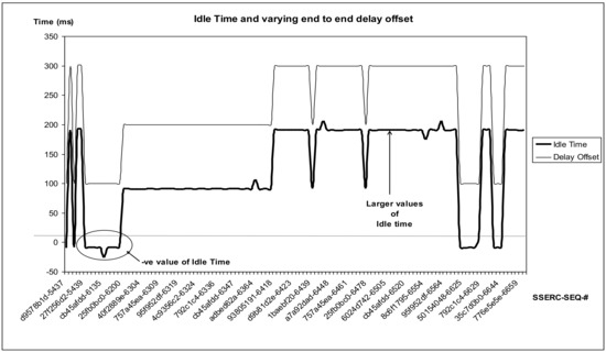
Figure 14.
End-to-end delay offset and its effect on idle time.
6. Conclusions
A modification of RTCP has been presented to fulfill the given requirements. Two new APP packets are added to the RTCP to communicate the synchronization information between sender and receivers. It also makes use of RR packets to provide information required by the sender application. The size of newly added APP packets is not consuming a considerable amount of bandwidth under good network conditions. Depending upon the application, sender and receivers are required to have extra buffering space. Implementation results show that the proposed algorithm achieved accurately synchronized playout on all the receivers under all the possible scenarios defined in the experimental setup.
Acknowledgments
We are thankful to Ericsson Research Corporate Unit, Luleå, Sweden for their kind support during the implementation phases of this project. This work is financially supported by National Natural Science Foundation of China (Grant Nos. 61631018, 61461136002).
Author Contributions
Rab Nawaz Jadoon, WuYang Zhou, Faizan ul Haq and Jawad Shafi conceived and designed the experiments; Rab Nawaz Jadoon and Faizan ul Haq performed the experiments; Rab Nawaz Jadoon, Iftikhar Ahmed Khan and Waqas Jadoon analyzed the data; Rab Nawaz Jadoon wrote the paper and Iftikhar Ahmed khan and Waqas Jadoon technically reviewed the paper.
Conflicts of Interest
The authors declare no conflict of interest.
References
- Chang, X.; Ma, Z.; Lin, M.; Yang, Y.; Hauptmann, A.G. Feature interaction augmented sparse learning for fast kinect motion detection. IEEE Trans. Image Process. 2017, 26, 3911–3920. [Google Scholar] [CrossRef] [PubMed]
- Chang, X.; Ma, Z.; Yang, Y.; Zeng, Z.; Hauptmann, A.G. Bi-level semantic representation analysis for multimedia event detection. IEEE Trans. Cybern. 2017, 47, 1180–1197. [Google Scholar] [CrossRef] [PubMed]
- Chang, X.; Yu, Y.-L.; Yang, Y.; Xing, E.P. Semantic pooling for complex event analysis in untrimmed videos. IEEE Trans. Pattern Anal. Mach. Intell. 2017, 39, 1617–1632. [Google Scholar] [CrossRef] [PubMed]
- Li, Z.; Nie, F.; Chang, X.; Yang, Y. Beyond Trace Ratio: Weighted Harmonic Mean of Trace Ratios for Multiclass Discriminant Analysis. IEEE Trans. Knowl. Data Eng. 2017, 29, 2100–2110. [Google Scholar] [CrossRef]
- Chang, X.; Yang, Y. Semisupervised feature analysis by mining correlations among multiple tasks. IEEE Trans. Neural Netw. Learn. Syst. 2017, 28, 2294–2305. [Google Scholar] [CrossRef] [PubMed]
- Blakowski, G.; Steinmetz, R. A media synchronization survey: Reference model, specification, and case studies. IEEE J. Sel. Areas Commun. 1996, 14, 5–35. [Google Scholar] [CrossRef]
- Jacobson, V.; Frederick, R.; Casner, S.; Schulzrinne, H. RTP: A Transport Protocol for Real-Time Applications; RFC Editor: Marina del Rey, CA, USA, 2003. [Google Scholar]
- Liu, C. Multimedia over IP: RSVP, RTP, RTCP, RTSP. In Handbook of Emerging Communication Technologies; Osso, R., Ed.; CRC Press: New York, NY, USA; Washington, DC, USA, 1997; pp. 29–46. [Google Scholar]
- Mills, D. Network Time Protocol (Version 3) Specification, Implementation and Analysis; University of Delaware: Newark, DE, USA, 1992. [Google Scholar]
- Perkins, C. RTP: Audio and Video for the Internet; Addison-Wesley Professional: Boston, MA, USA, 2003. [Google Scholar]
- Ott, J.; Carrara, E. Extended Secure RTP Profile for Real-Time Transport Control Protocol (RTCP)-Based Feedback (RTP/SAVPF); Helsinki University of Technology: Espoo, Finland, 2008. [Google Scholar]
- Mills, D.L. Internet time synchronization: the network time protocol. IEEE Trans. Commun. 1991, 39, 1482–1493. [Google Scholar] [CrossRef]
- Little, T.D.C.; Chen, C.Y.R.; Chang, C.S.; Berra, P.B. Multimedia synchronization. IEEE Data Eng. Bull. 1991, 14, 26–35. [Google Scholar]
- Schulzrinne, H. RTP Profile for Audio and Video Conferences with Minimal Control; RFC 3551; RFC Editor: Marina del Rey, CA, USA, 2003. [Google Scholar]
- Rangan, P.V.; Ramanathan, S.; Sampathkumar, S. Feedback techniques for continuity and synchronization in multimedia information retrieval. ACM Trans. Inf. Syst. 1995, 13, 145–176. [Google Scholar] [CrossRef]
- Firestone, S.; Ramalingam, T.; Fry, S. Voice and Video Conferencing Fundamentals, 1st ed.; Cisco Press: Indianapolis, IN, USA, 2007; Chapter 6; p. 185. [Google Scholar]
- Jung, T.-J.; Seo, K.-D. A client-driven media synchronization mechanism for RTP packet-based video streaming. J. Real-Time Image Process. 2016, 12, 455–464. [Google Scholar] [CrossRef]
- Akyildiz, I.F.; Yen, W. Multimedia group synchronization protocols for integrated services networks. IEEE J. Sel. Areas Commun. 1996, 14, 162–173. [Google Scholar] [CrossRef]
- Diot, C.; Gautier, L. A distributed architecture for multiplayer interactive applications on the Internet. IEEE Netw. 1999, 13, 6–15. [Google Scholar] [CrossRef]
- Ishibashi, Y.; Tasaka, S.; Miyamoto, H. Joint synchronization between stored media with interactive control and live media in multicast communications. IEICE Trans. Commun. 2002, 85, 812–822. [Google Scholar]
- Seguí, F.B.; Cebollada, J.C.G.; Mauri, J.L. Multimedia group synchronization algorithm based on RTP/RTCP. In Proceedings of the Eighth IEEE International Symposium on Multimedia, 2006 (ISM’06), San Diego, CA, USA, 11–13 December 2016; pp. 754–757. [Google Scholar]
- Montagud, M.; Boronat, F. Enhanced adaptive RTCP-based Inter-Destination Multimedia Synchronization approach for distributed applications. Comput. Netw. 2012, 56, 2912–2933. [Google Scholar] [CrossRef]
© 2018 by the authors. Licensee MDPI, Basel, Switzerland. This article is an open access article distributed under the terms and conditions of the Creative Commons Attribution (CC BY) license (http://creativecommons.org/licenses/by/4.0/).