Figure 1.
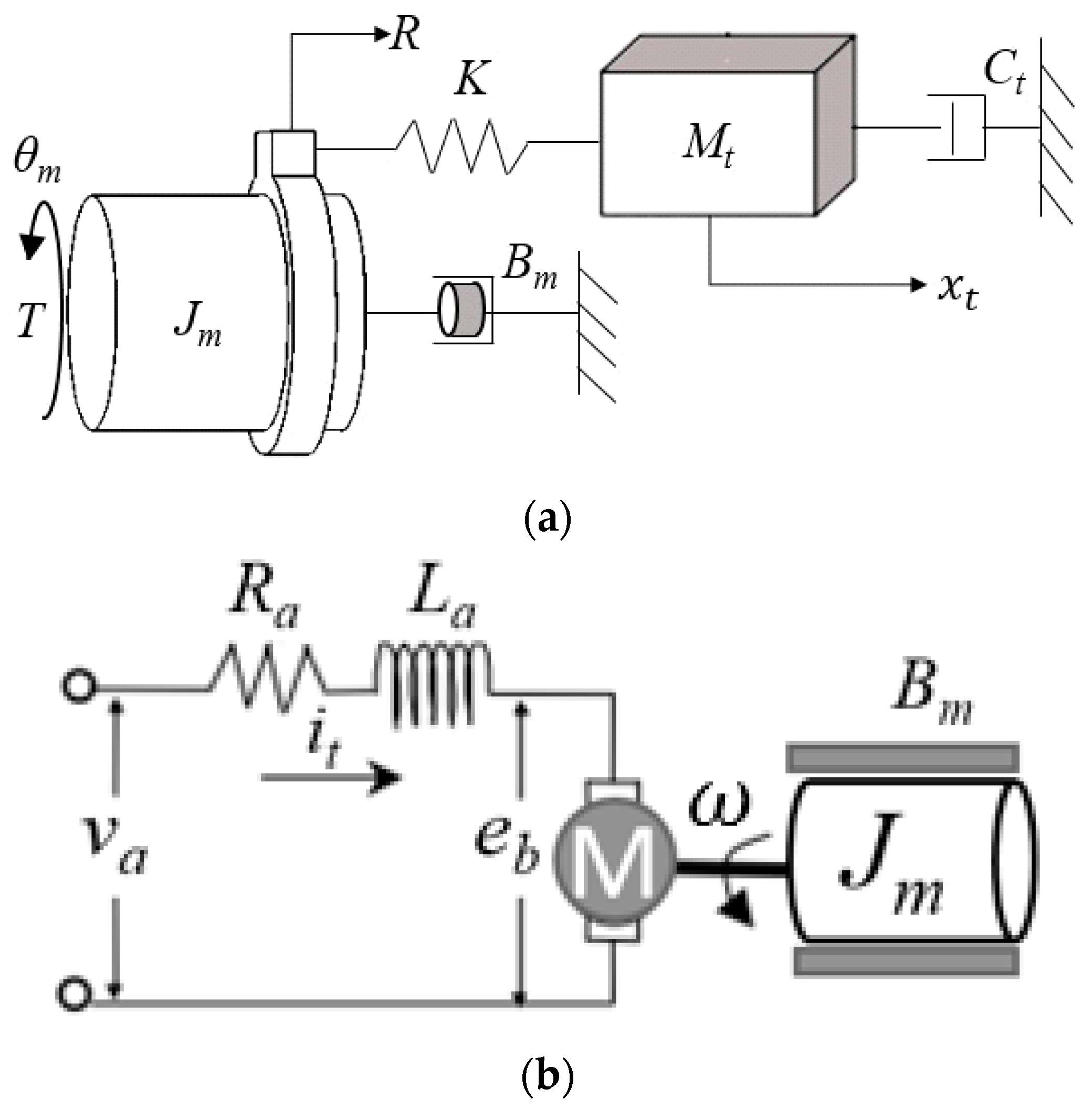
Dynamic model of single-axis feed drive system; (a) mechanical dynamics, (b) motor dynamics.
Figure 1.
Dynamic model of single-axis feed drive system; (a) mechanical dynamics, (b) motor dynamics.
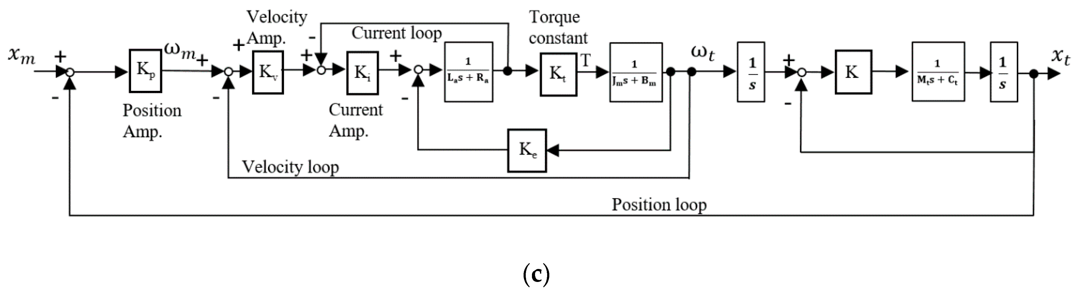
Figure 2.
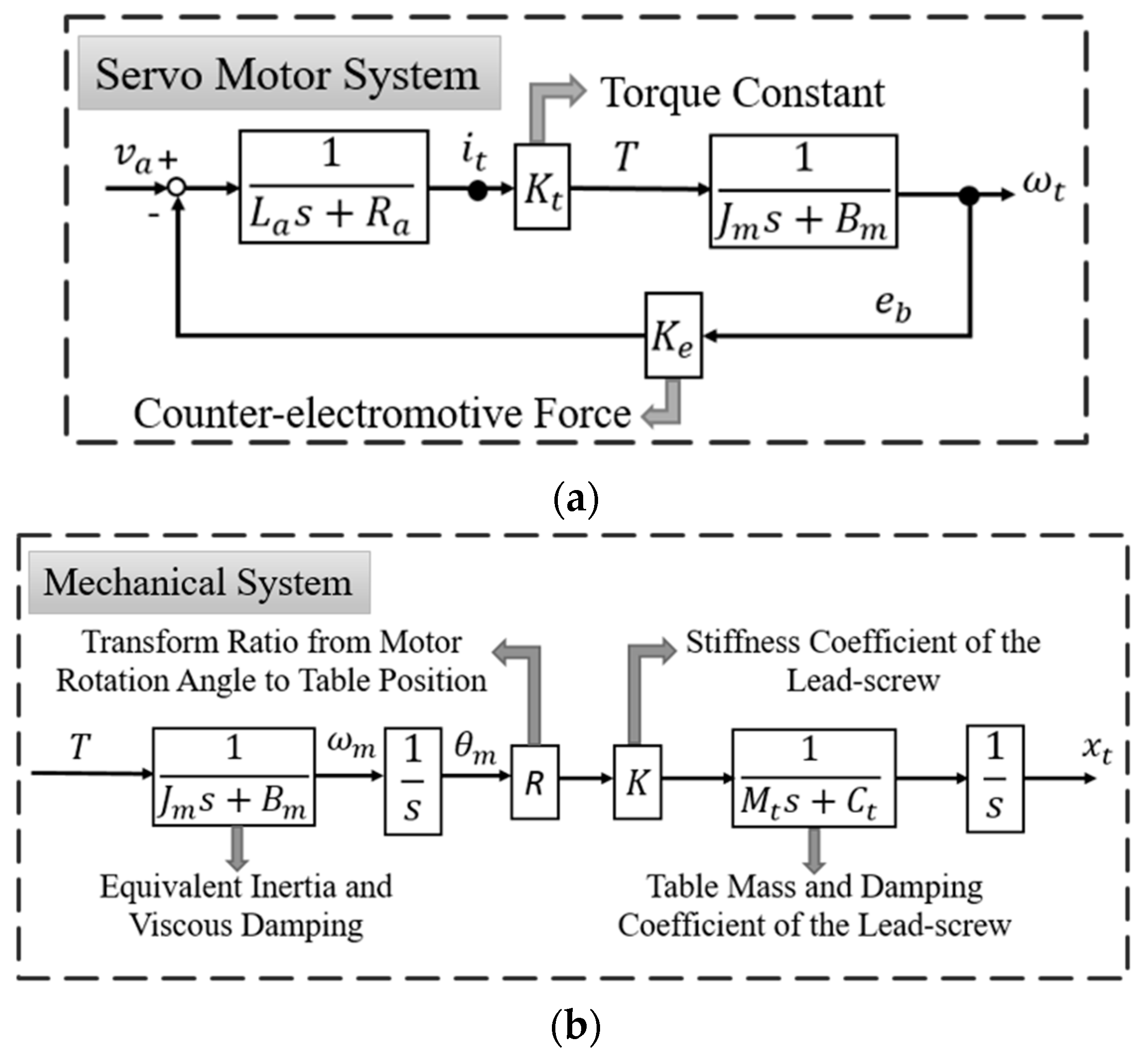
Block diagram of feed drive system; (a) Servo motor system; (b) Mechanical system; and (c) Closed-loop systems.
Figure 2.
Block diagram of feed drive system; (a) Servo motor system; (b) Mechanical system; and (c) Closed-loop systems.
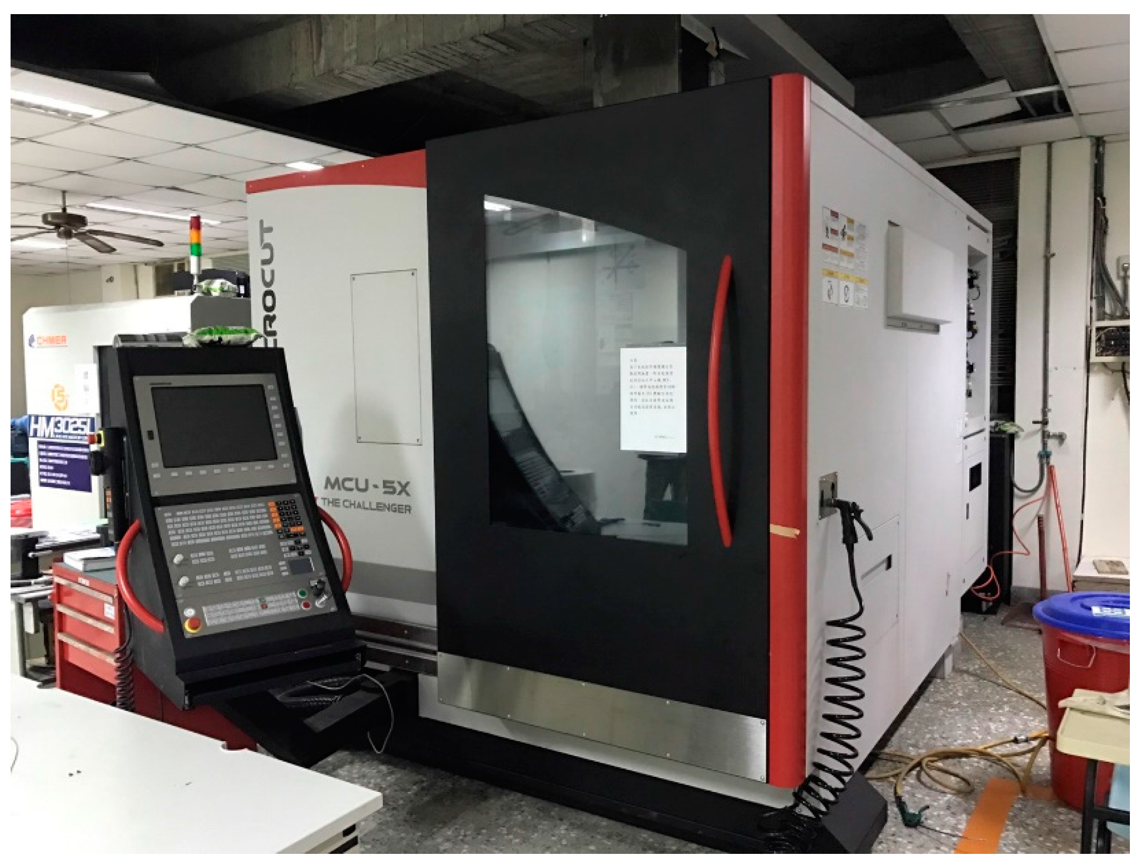
Figure 3.
Five-axis machine tool MCU-5X in National Chung Hsing University (NCHU).
Figure 3.
Five-axis machine tool MCU-5X in National Chung Hsing University (NCHU).
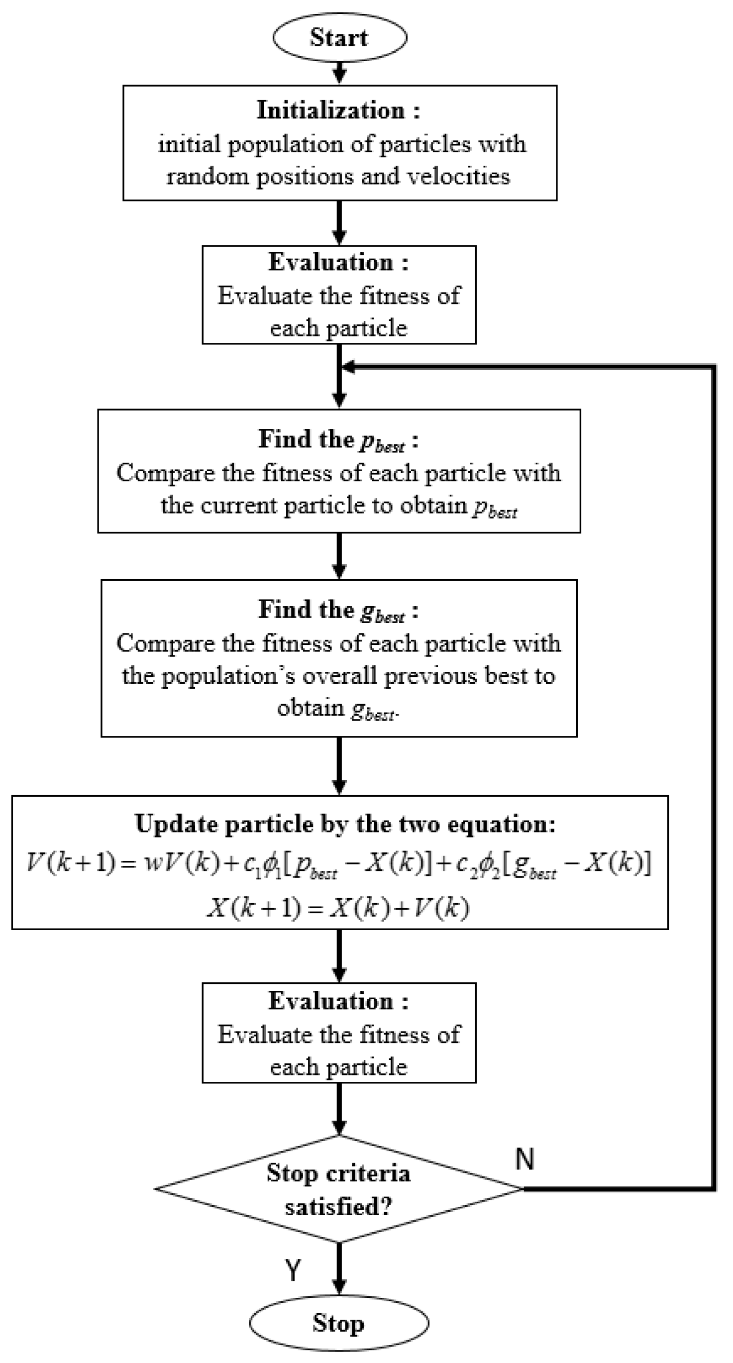
Figure 4.
The flow chart of the particle swarm optimization (PSO) algorithm.
Figure 4.
The flow chart of the particle swarm optimization (PSO) algorithm.
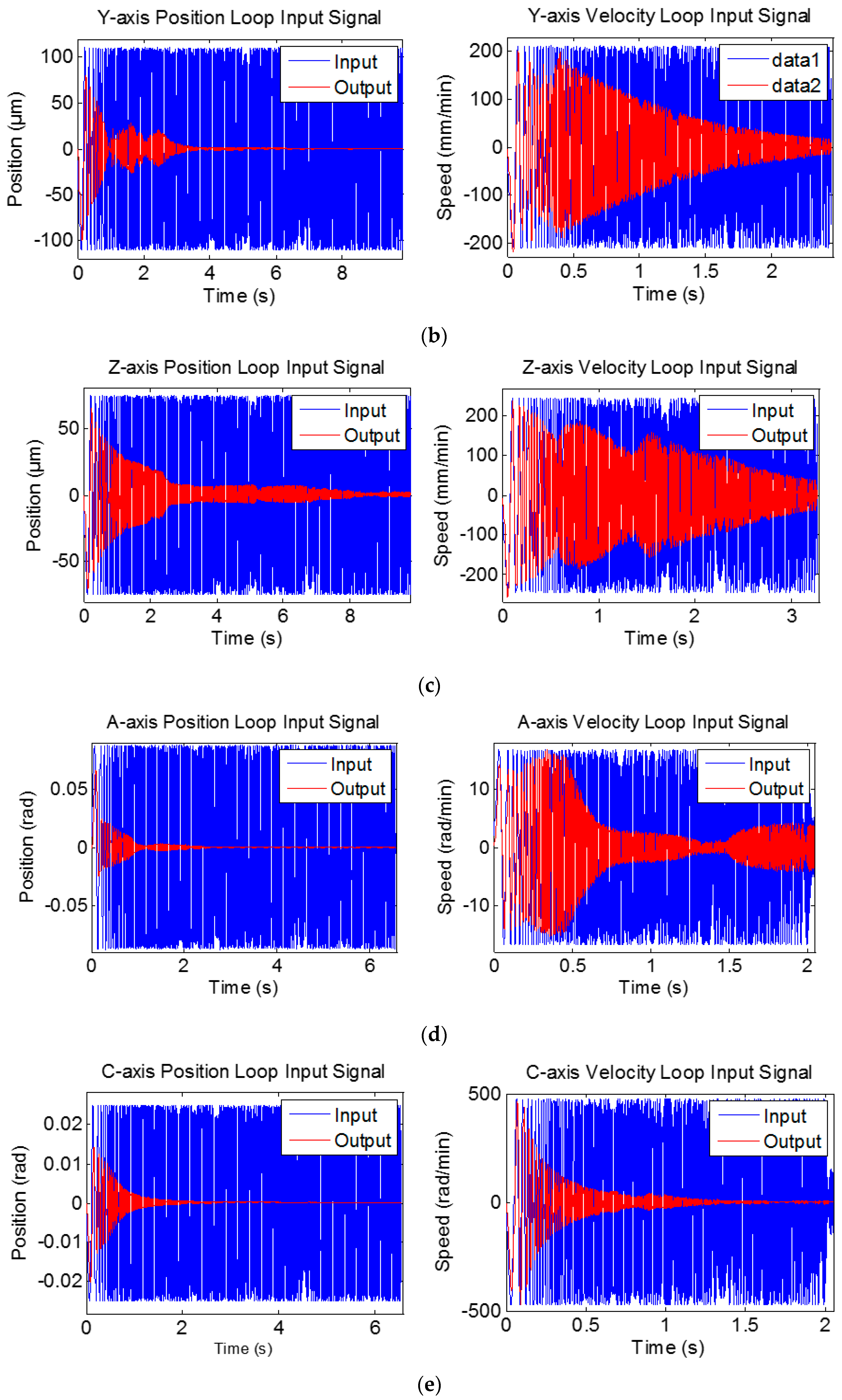
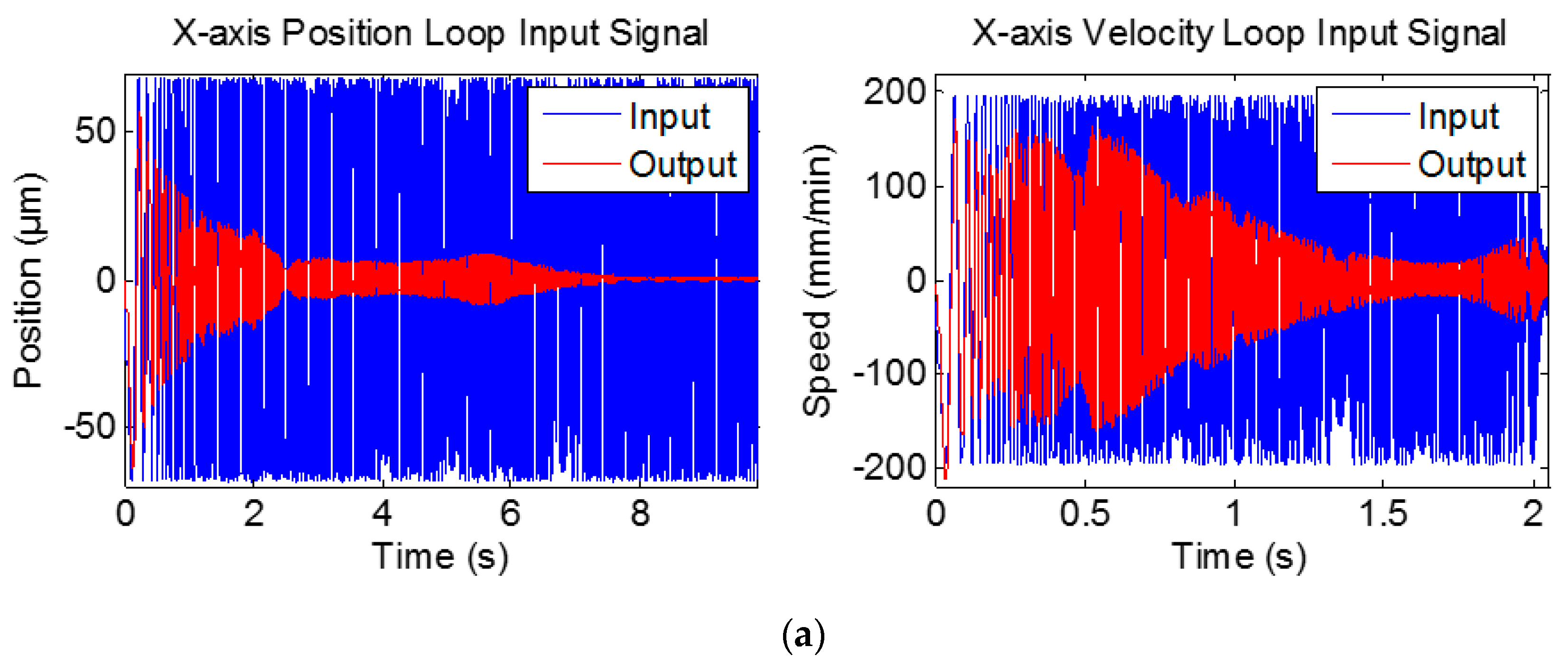
Figure 5.
Sine chirp input signals and the corresponding outputs for system identification. (a) X-axis (b) Y-axis (c) Z-axis (d) A-axis (e) C-axis.
Figure 5.
Sine chirp input signals and the corresponding outputs for system identification. (a) X-axis (b) Y-axis (c) Z-axis (d) A-axis (e) C-axis.
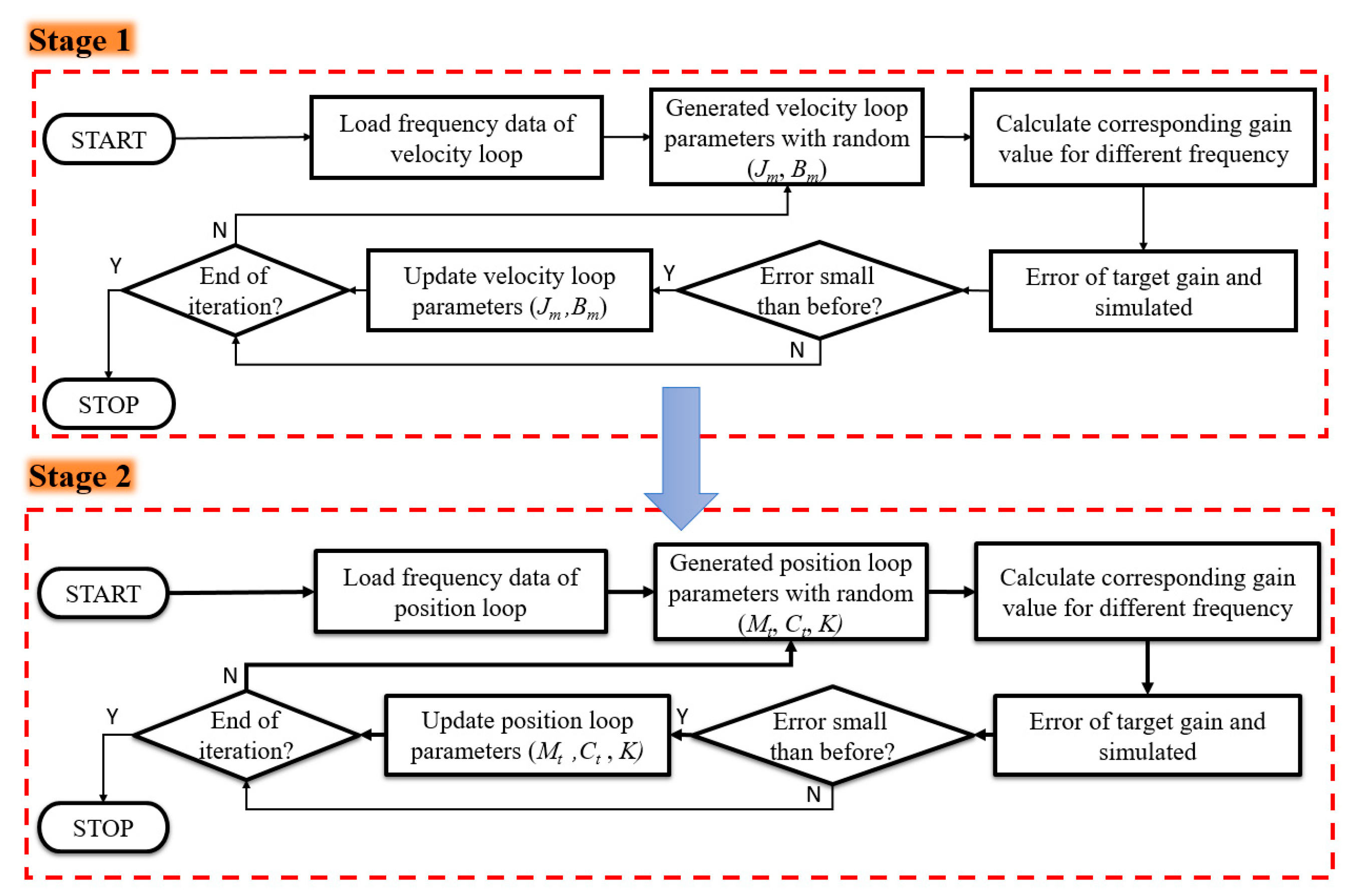
Figure 6.
Two-stage approach for system identification.
Figure 6.
Two-stage approach for system identification.
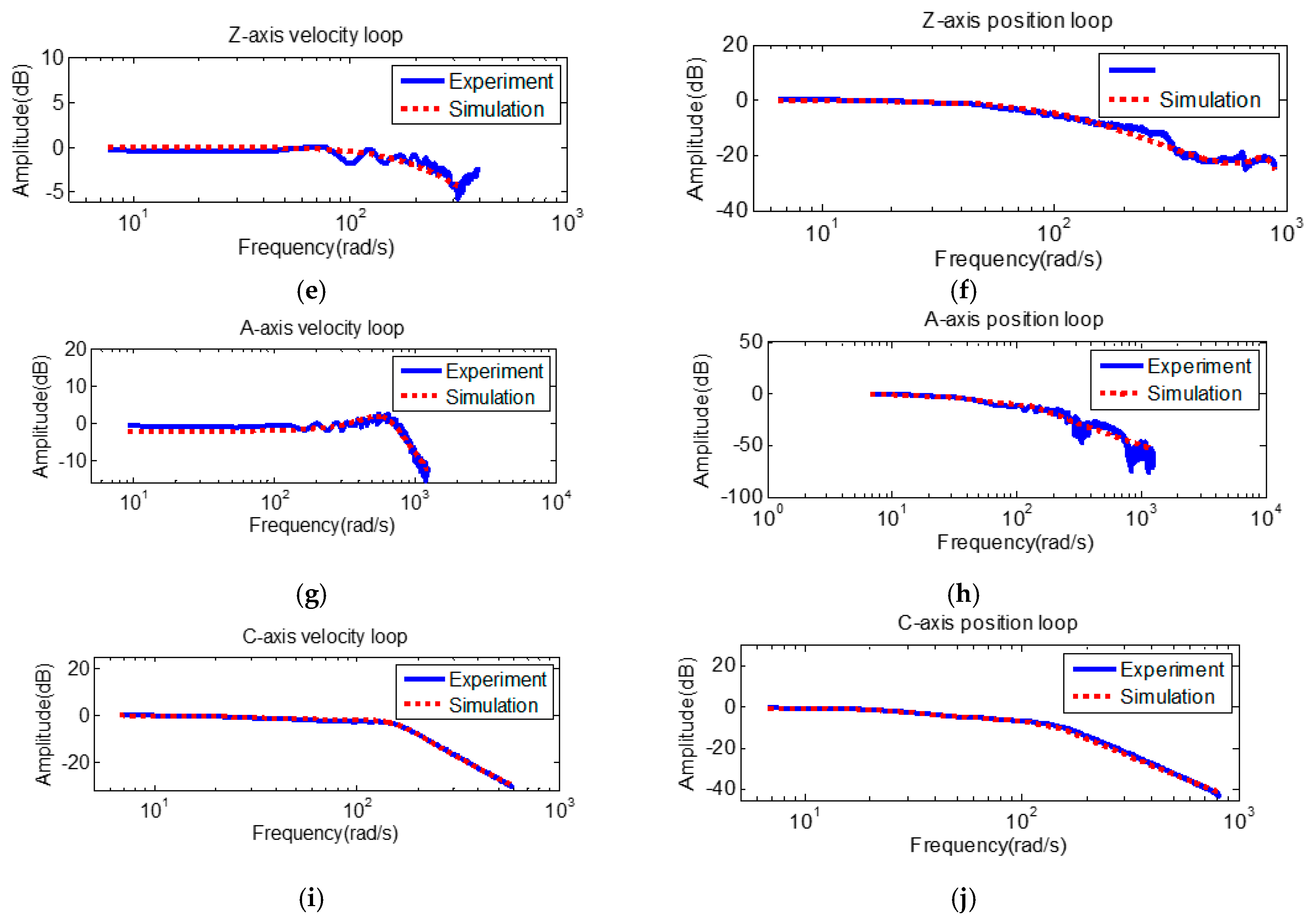
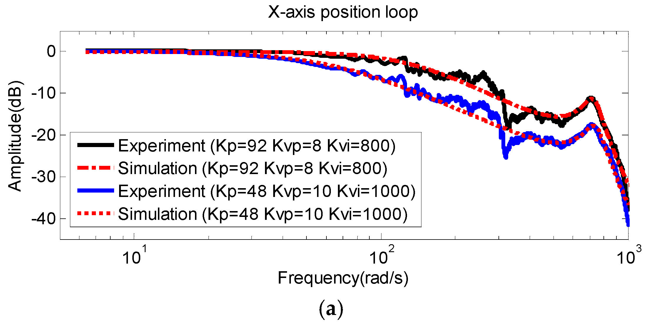
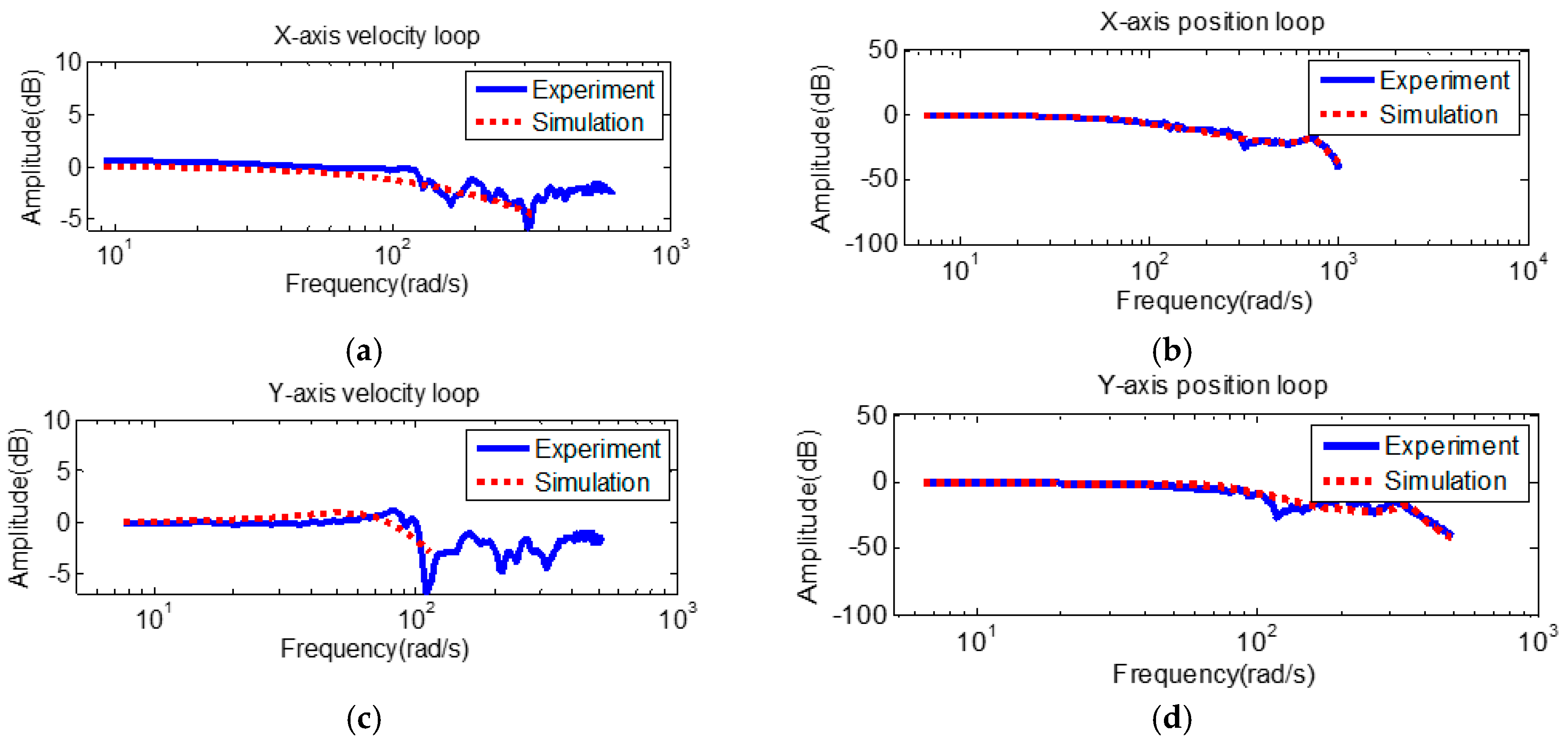
Figure 7.
Frequency responses of velocity loop and position loop. (a) X-axis: velocity loop. (b) X-axis: position loop. (c) Y-axis: velocity loop. (d) Y-axis: position loop. (e) Z-axis: velocity loop. (f) Z-axis: position loop. (g) A-axis: velocity loop. (h) A-axis: position loop. (i) C-axis: velocity loop. (j) C-axis: position loop.
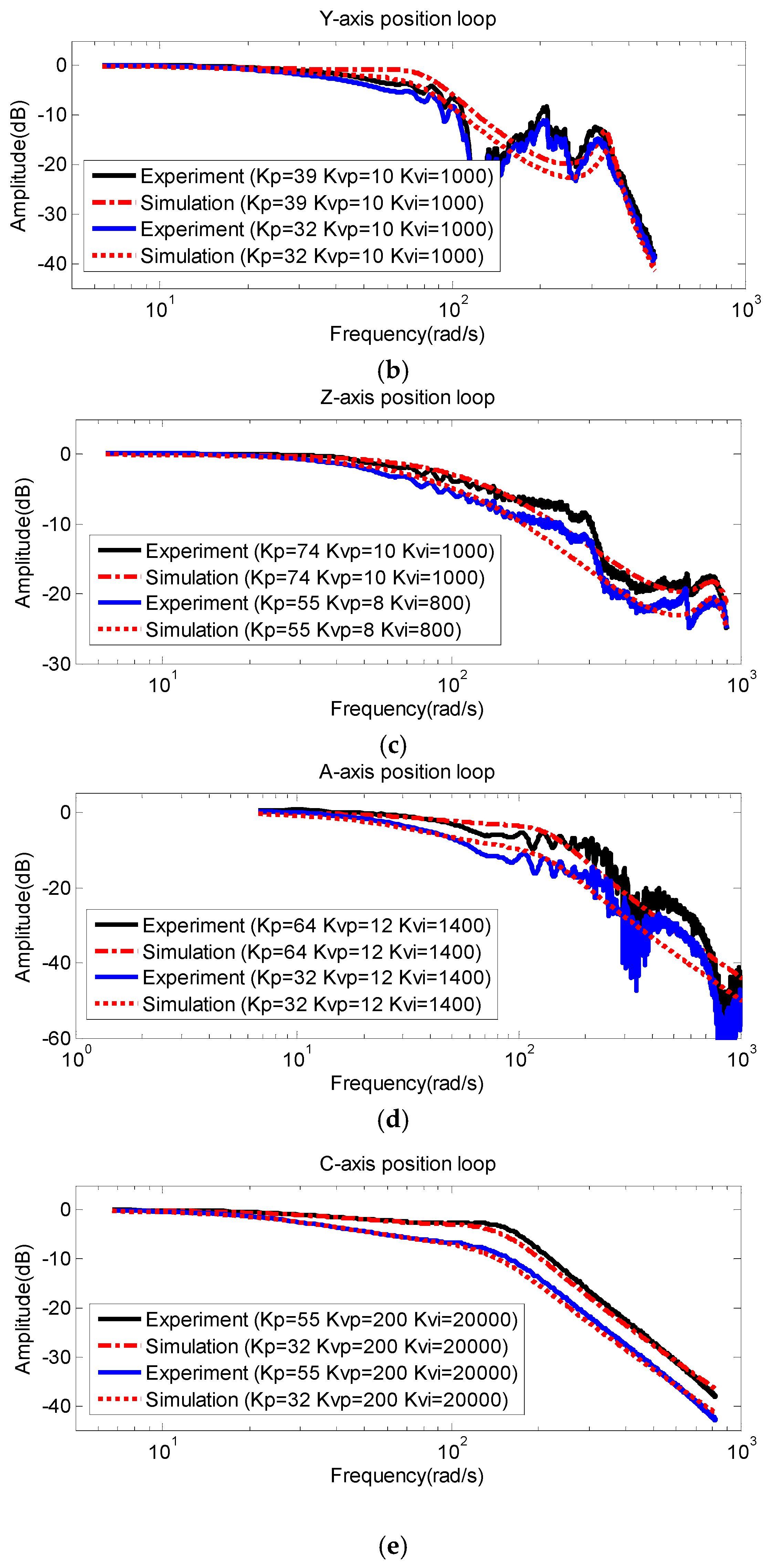
Figure 8.
FRF comparison results of experiment and simulation. (a) X-axis, (b) Y-axis, (c) Z-axis, (d) A-axis, (e) C-axis.
Figure 8.
FRF comparison results of experiment and simulation. (a) X-axis, (b) Y-axis, (c) Z-axis, (d) A-axis, (e) C-axis.
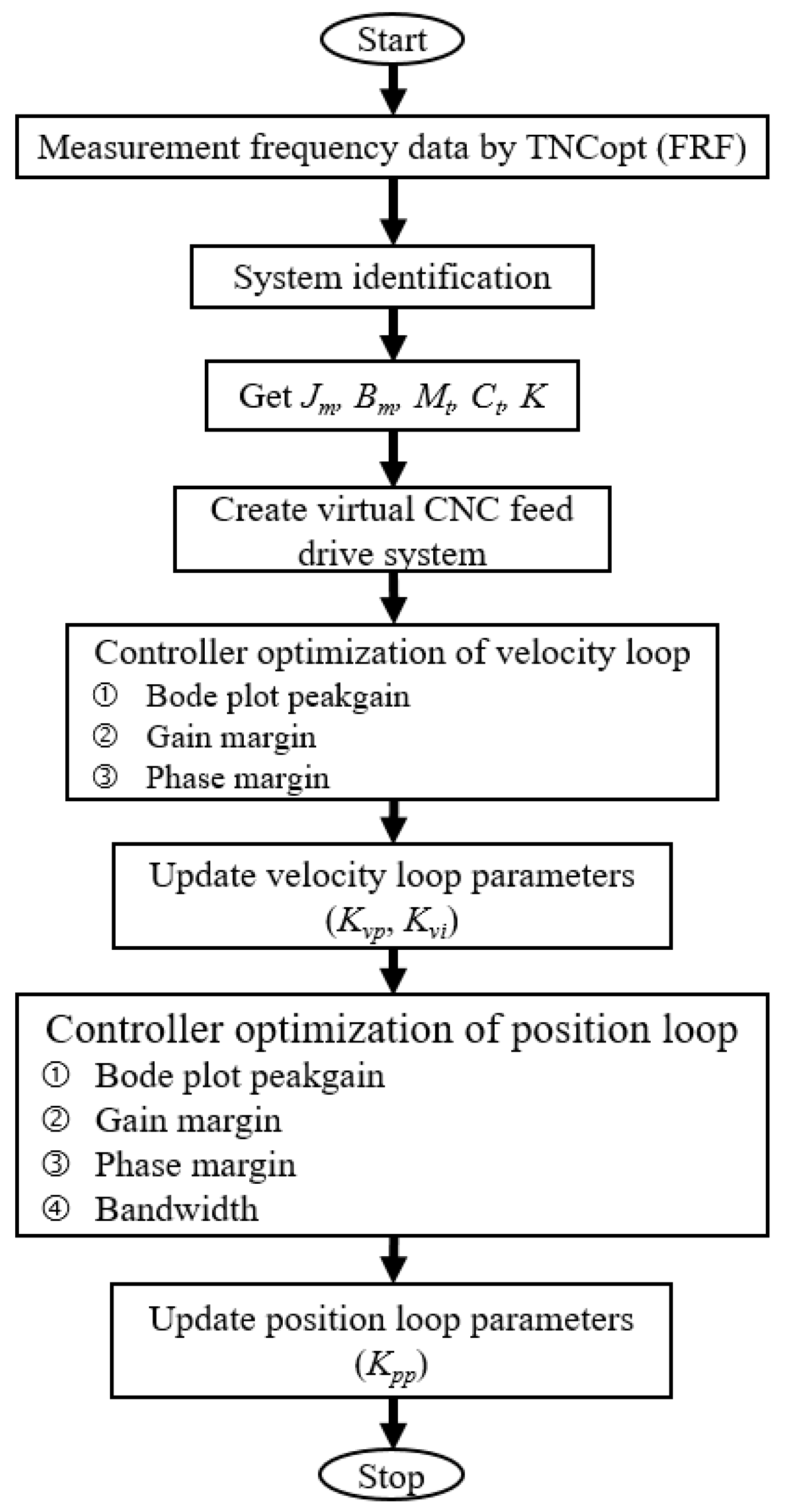
Figure 9.
Intelligent tuning servo system flowchart.
Figure 9.
Intelligent tuning servo system flowchart.
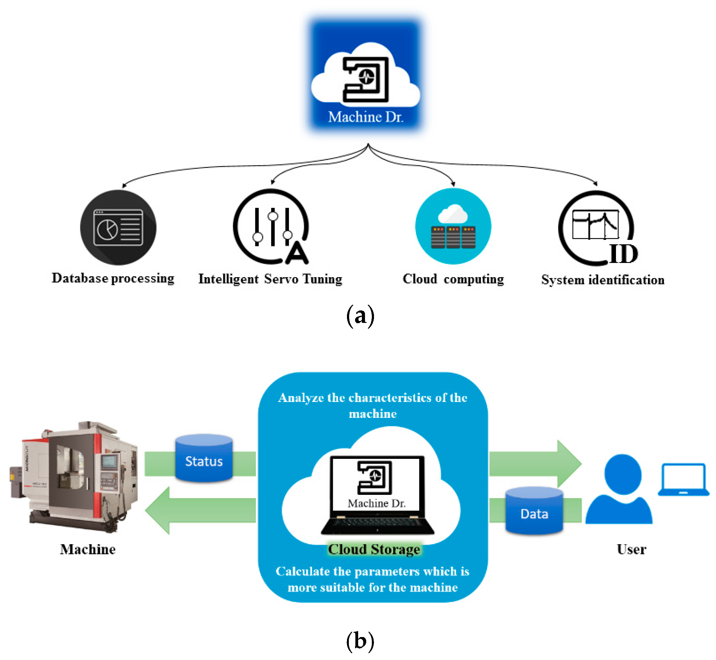
Figure 10.
Illustration of the cloud platform—Machine Dr. system; (a) functions illustration; (b) communication between the user and the cloud servo system.
Figure 10.
Illustration of the cloud platform—Machine Dr. system; (a) functions illustration; (b) communication between the user and the cloud servo system.
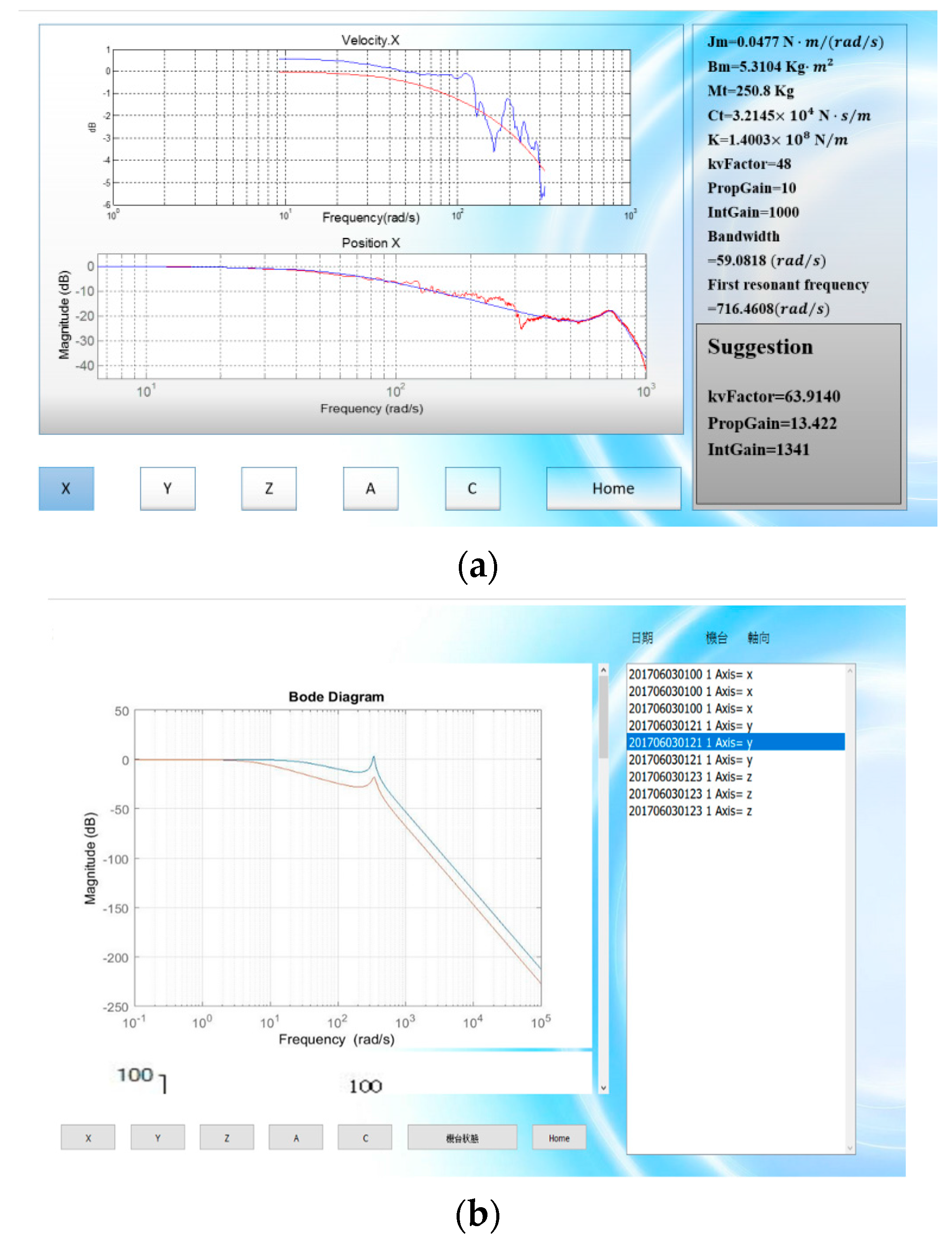
Figure 11.
Operation illustration of the Machine Dr. (a) Auto-tuning screen; (b) Operation history data screen.
Figure 11.
Operation illustration of the Machine Dr. (a) Auto-tuning screen; (b) Operation history data screen.
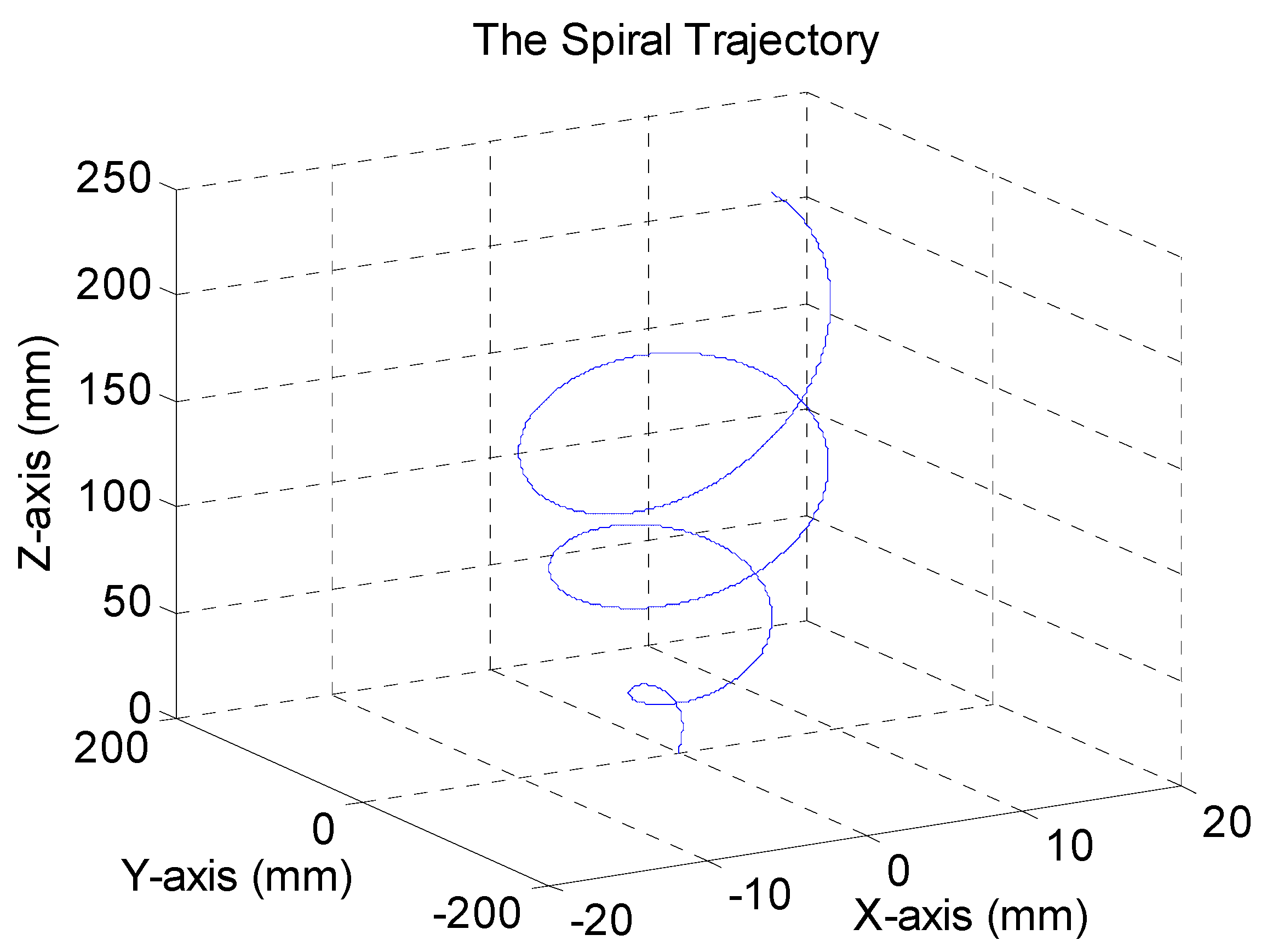
Figure 12.
Spiral trajectory.
Figure 12.
Spiral trajectory.
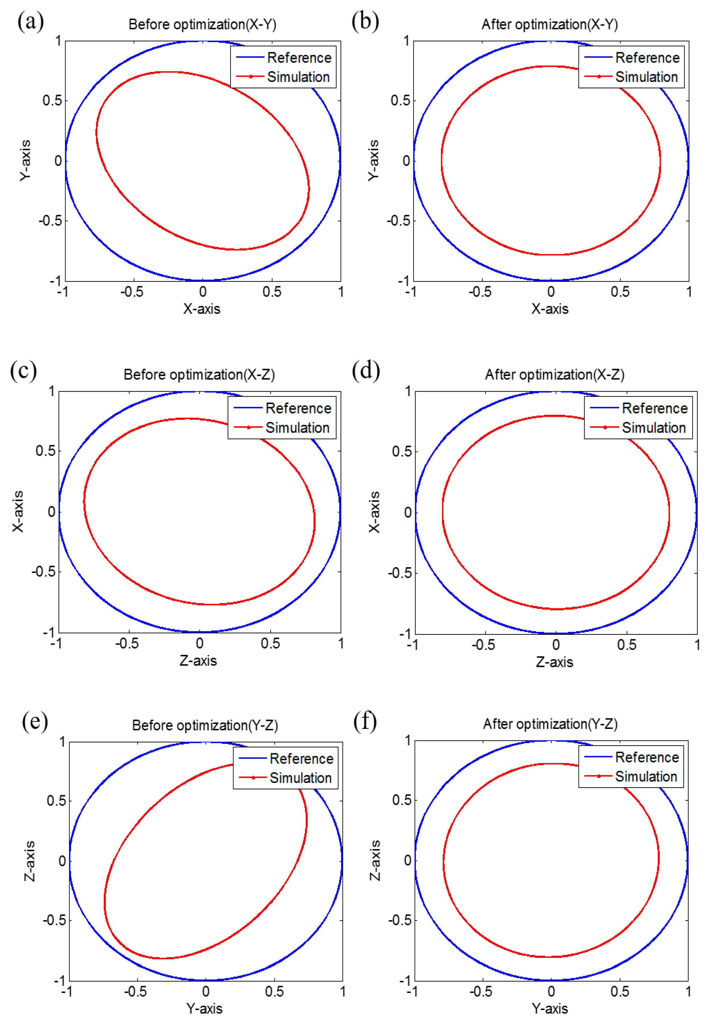
Figure 13.
Simulation result of circular motion tests. (a) Before optimization (X-Y), (b) After optimization (X-Y), (c) Before optimization (X-Z), (d) After optimization (X-Z), (e) Before optimization (Y-Z), (f) After optimization (Y-Z).
Figure 13.
Simulation result of circular motion tests. (a) Before optimization (X-Y), (b) After optimization (X-Y), (c) Before optimization (X-Z), (d) After optimization (X-Z), (e) Before optimization (Y-Z), (f) After optimization (Y-Z).
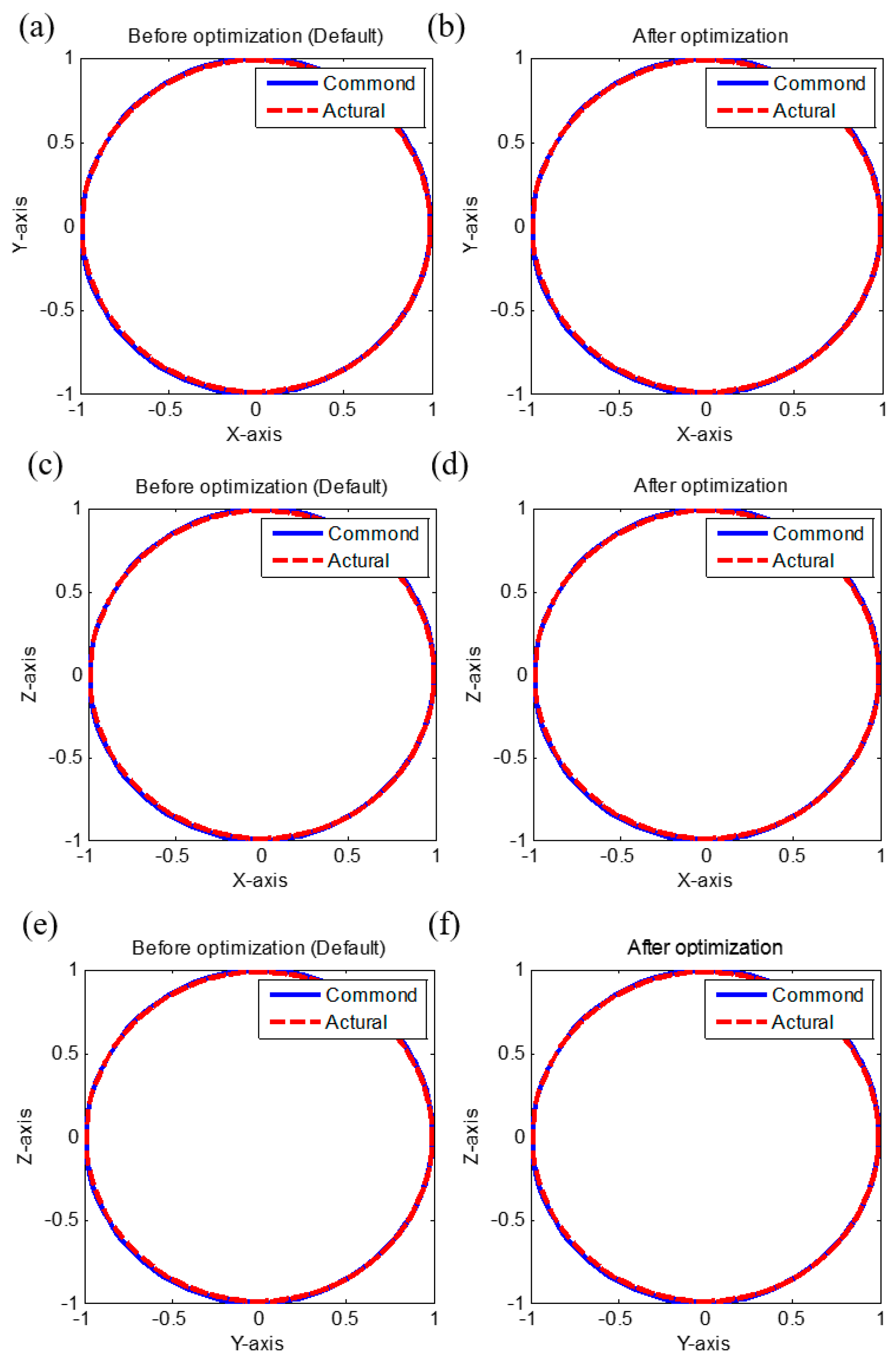
Figure 14.
Experiment result of circular tests. (a) X-Y axis (default setting), (b) X-Y axis (optimized setting), (c) X-Z axis (default setting), (d) X-Z axis (optimized setting), (e) Y-Z axis (default setting), (f) Y-Z axis (optimized setting).
Figure 14.
Experiment result of circular tests. (a) X-Y axis (default setting), (b) X-Y axis (optimized setting), (c) X-Z axis (default setting), (d) X-Z axis (optimized setting), (e) Y-Z axis (default setting), (f) Y-Z axis (optimized setting).
Table 1.
Major specifications of the machine tool (MCU-5X).
Table 1.
Major specifications of the machine tool (MCU-5X).
| Specifications | Values |
|---|
| X/Y/Z Axis Travel (mm) | 600/600/500 |
| Tilting Axis A (degree) | +120/−120 |
| Rotary C (degree) | 360 |
| Rapid Traverse X/Y/Z (mm/min) | 36,000/36,000/36,000 |
| Max. Speed A/C (rpm) | 16.6/90 |
| Spindle Speed Range (rpm) | 12,000 (std)/15,000 (opt) |
| Type of Position Control | Full-closed control |
Table 2.
The results of identification for each axis.
Table 2.
The results of identification for each axis.
| Parameters | X-Axis | Y-Axis | Z-Axis | A-Axis | C-Axis |
|---|
| Jm | | | | | |
| Bm | | | | | 0 |
| Mt | | | | --- | --- |
| Ct | | | | --- | --- |
| K | | | | --- | --- |
| Bandwidth (Hz) | | | | | |
| Resonance frequency (Hz) | | | | --- | --- |
Table 3.
Root mean square error (RMSE) of each axis for time responses.
Table 3.
Root mean square error (RMSE) of each axis for time responses.
| Error\Axis | X-Axis | Y-Axis | Z-Axis | A-Axis | C-Axis |
|---|
| RMSE | 3.4791 () | 6.5061 () | 4.3310 () | 0.0005 (rad) | 0.0002 (rad) |
Table 4.
Comparison results of tuning results between one-step and two-steps.
Table 4.
Comparison results of tuning results between one-step and two-steps.
| Two-Step | 1 | 2 | 3 | 4 | 5 | 6 |
| Time (s) | 199.9 | 210.8 | 323.5 | 344.4 | 513.3 | 501.9 |
| Bandwidth (rad/s) | 81.23 | 82.95 | 82.95 | 84.55 | 84.55 | 84.55 |
| Particle (PSO) | 25 | 30 | 30 | 35 | 35 | 40 |
| Iteration (PSO) | 200 | 200 | 500 | 500 | 600 | 600 |
| One-Step | 1 | 2 | 3 | 4 | 5 | 6 |
| Time (s) | 371.7 | 440.5 | 687.2 | 712.9 | 833.4 | 904.2 |
| Bandwidth (rad/s) | 42.58 | 27.33 | 41.14 | 43.64 | 42.74 | 79.18 |
| Particle (PSO) | 25 | 30 | 30 | 35 | 35 | 40 |
| Iteration (PSO) | 200 | 200 | 500 | 500 | 600 | 600 |
Table 5.
Proportional-integral (PI) controller parameters and bandwidth values.
Table 5.
Proportional-integral (PI) controller parameters and bandwidth values.
| Before Optimization |
| Parameters | X-axis | Y-axis | Z-axis | A-axis | C-axis |
| Kpp | 48 | 32 | 55 | 32 | 32 |
| Kvp | 10 | 10 | 8 | 12 | 200 |
| Kvi | 1000 | 1000 | 800 | 1400 | 20,000 |
| Bandwidth (Hz) | 9.3771 | 7.2411 | 10.6631 | 4.500 | 9.4743 |
| After Optimization by PSO |
| Parameters | X-axis | Y-axis | Z-axis | A-axis | C-axis |
| Kpp | | | | | |
| Kvp | | | | | |
| Kvi | | | | | |
| Bandwidth (Hz) | | | | | |
Table 6.
Simulation result of spiral trajectory.
Table 6.
Simulation result of spiral trajectory.
| Tracking Error | X-Axis | Y-Axis | Z-Axis | Contouring Error |
|---|
| Before optimization | 0.0017 | 0.0299 | 0.0027 | 0.0173 |
| After optimization | 0.0013 | 0.0197 | 0.0023 | 0.0164 |
| improvement | 23.53% | 34.11% | 14.81% | 5.20% |
Table 7.
Simulation result of rotation axes.
Table 7.
Simulation result of rotation axes.
| Tracking Error | A-Axis | C-Axis |
|---|
| Before optimization | | |
| After optimization | | |
| improvement | 40.28% | 51.38% |
Table 8.
Contour error and tracking error RMSE of circular motion.
Table 8.
Contour error and tracking error RMSE of circular motion.
| Simulation Result of Circular Motion |
|---|
| Axes\Errors | Contouring Error | Tracking Error |
|---|
| RMSE (mm) | Max. (mm) | RMSE (mm) | Max. (mm) |
|---|
| X-Y Axes | Default | 0.2566 | 0.2637 | 1.1497 | 1.1567 |
| Our approach | 0.2079 | 0.2136 | 1.1362 | 1.1418 |
| Improvement | 18.98% | 19.00% | 1.17% | 1.29% |
| X-Z Axes | Default | 0.2253 | 0.2617 | 1.1402 | 1.1772 |
| Our approach | 0.1984 | 0.2061 | 1.1330 | 1.1407 |
| Improvement | 11.94% | 21.25% | 0.63% | 3.10% |
| Y-Z Axes | Default | 0.2315 | 0.2743 | 1.1411 | 1.1852 |
| Our approach | 0.2027 | 0.2159 | 1.1342 | 1.1476 |
| Improvement | 12.44% | 21.29% | 0.60% | 3.17% |
Table 9.
Contour error and tracking error RMSE of circular test.
Table 9.
Contour error and tracking error RMSE of circular test.
| Experiment Result of Circular Motion |
|---|
| | Contouring Error | Tracking Error |
|---|
| RMSE (mm) | Max. (mm) | RMSE (mm) | Max. (mm) |
|---|
| X-Y Axes | Default | 0.0087 | 0.0326 | 0.2483 | 0.7863 |
| Our approach | 0.0076 | 0.0284 | 0.2478 | 0.7808 |
| Improvement | 12.64% | 12.88% | 0.201% | 0.700% |
| X-Z Axes | Default | 0.004 | 0.0142 | 0.2526 | 0.7753 |
| Our approach | 0.0036 | 0.0132 | 0.2525 | 0.7745 |
| Improvement | 10.00% | 7.04% | 0.04% | 0.103% |
| Y-Z Axes | Default | 0.0065 | 0.0196 | 0.2475 | 0.7790 |
| Our approach | 0.0060 | 0.0181 | 0.2474 | 0.7748 |
| Improvement | 7.69% | 7.65% | 0.04% | 0.54% |


