Cellular Automaton Modeling of the Transition of Multi-Crystalline Silicon from a Planar Faceted Front to Equiaxed Growth


Abstract
1. Introduction
2. Description of the Model and Numerical Calculation Method
2.1. LBM Model
2.2. CA Model
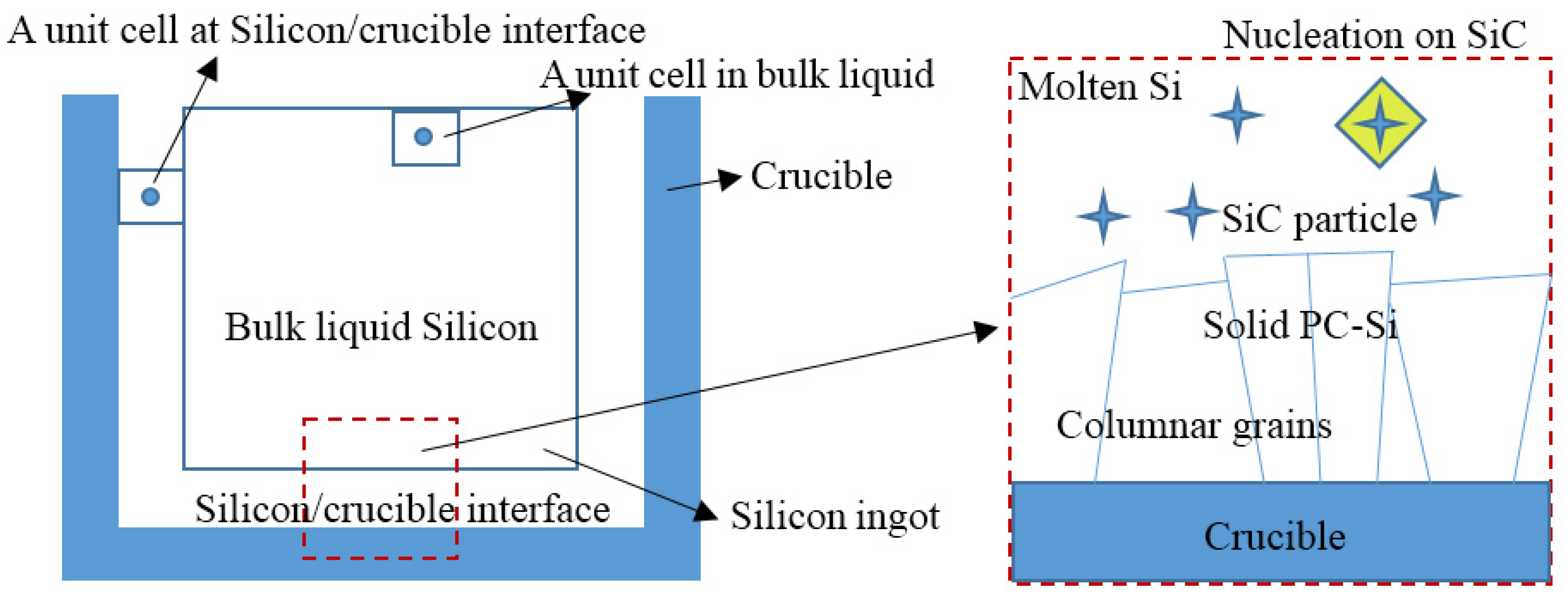
2.2.1. Nucleation
2.2.2. Model for the Growth of the Columnar Faceted Interface
2.2.3. Model for the Growth of the Thermal Equiaxed Dendrites
2.2.4. Model for the Growth of the Faceted Equiaxed Dendrites
2.3. Boundary Conditions
- (1)
- In the velocity field, four regional boundaries and solid-liquid boundary are disposed by the form of non-slipping rebound boundary [18].
- (2)
- In the temperature field, solid and liquid have the same heat transfer and the left, right and top boundary of the field is adiabatic. The heat dissipation of the bottom is in constant heat flux. The temperature distribution functions of the four boundaries are calculated by non-equilibrium extrapolation method.
- (3)
- In calculating solute field, the solute diffusion of the solid phase is ignored. The four regional boundaries are calculated by no diffusion boundary conditions and the solid-liquid boundary is calculated by rebound form.
2.4. The Physical Parameters of Silicon Melt
3 Simulation Results and Discussion
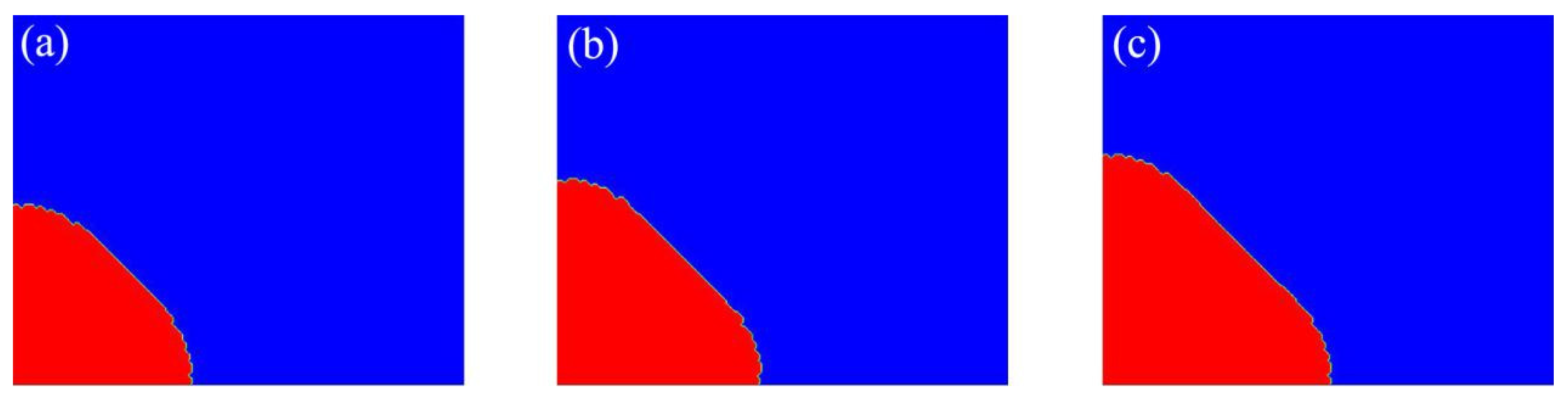
3.1. Validation of the Simulation of Faceted Growth by CA
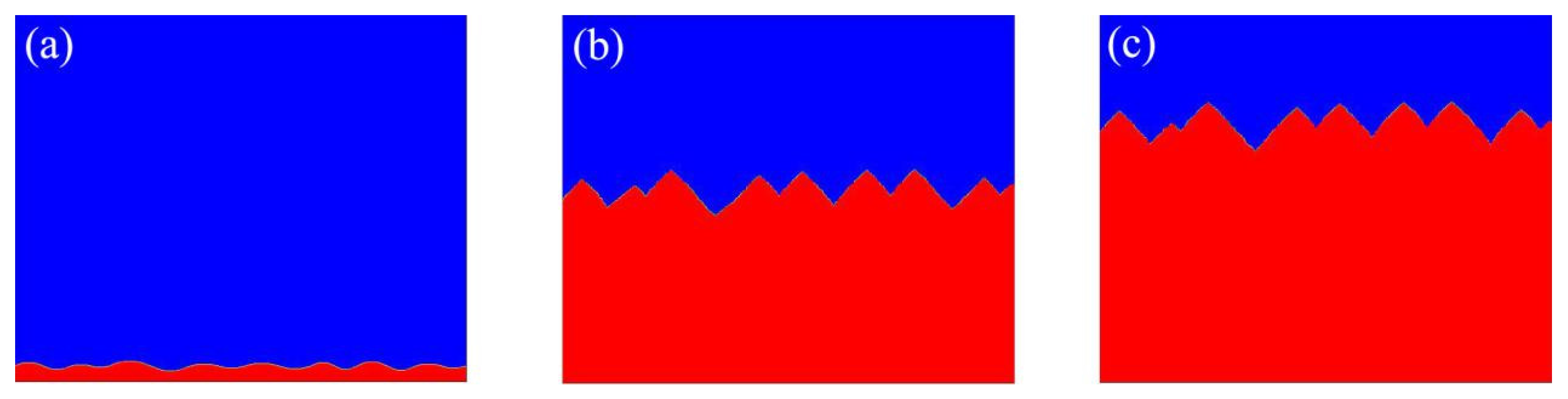
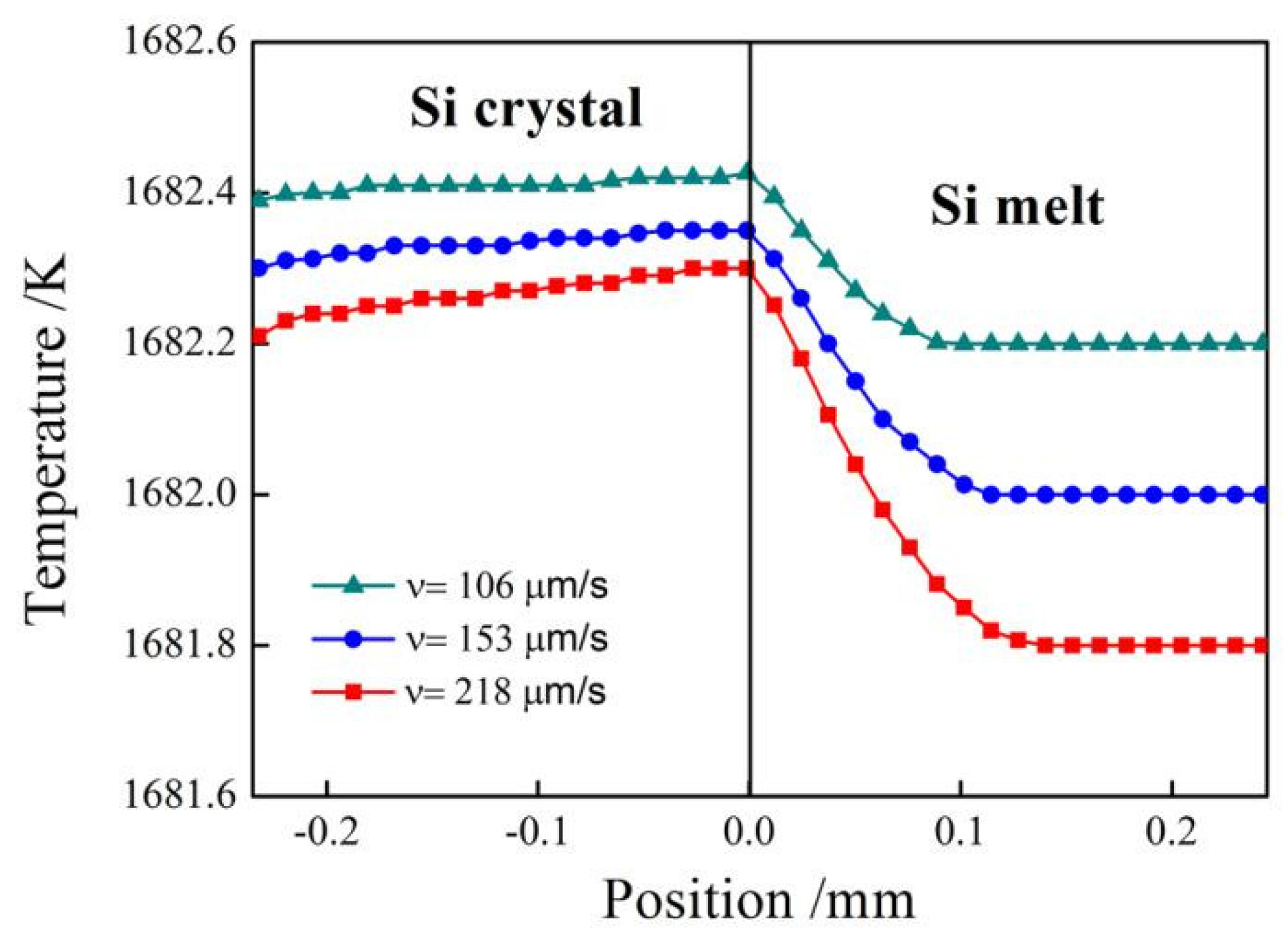
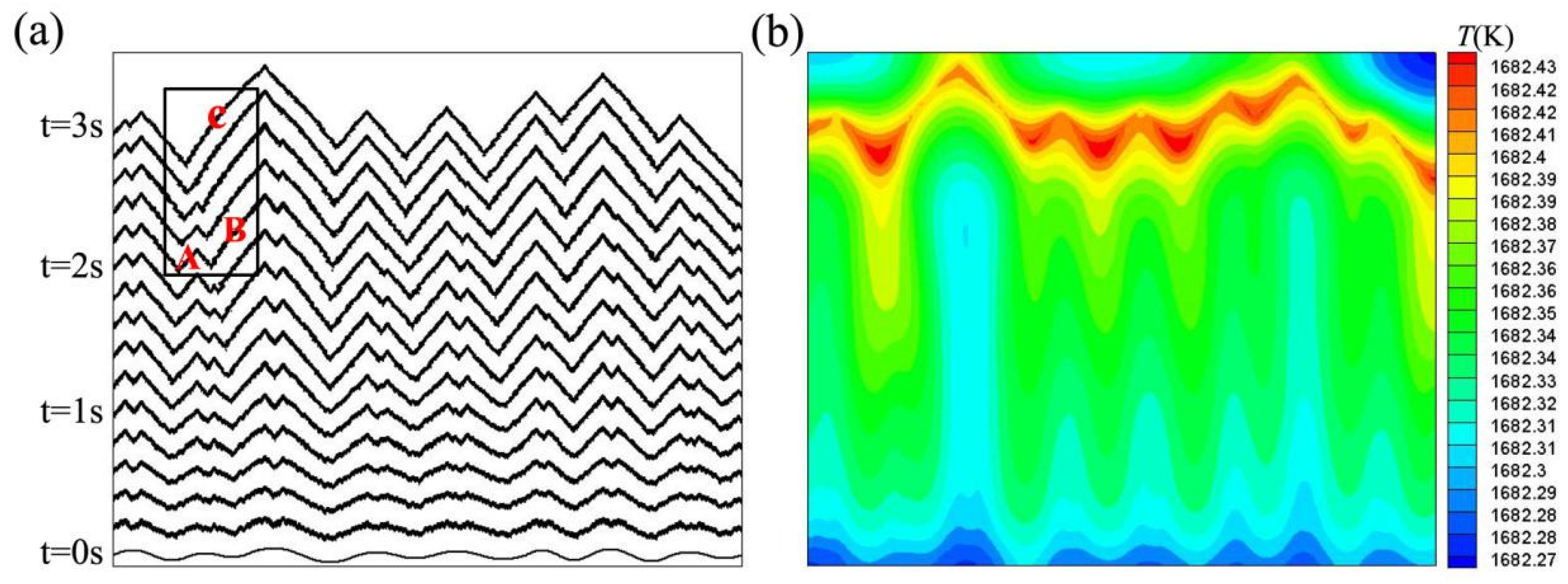
3.2. The Growth of the Faceted Interface
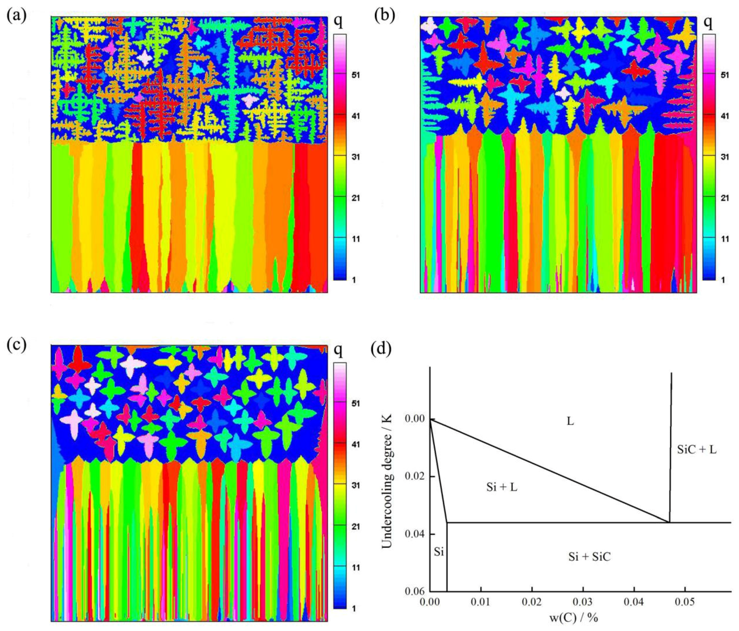
3.3. The Transition from Columnar Faceted Front to Equiaxed Growth
4. Conclusions
Acknowledgments
Author Contributions
Conflicts of Interest
References
- Goetzberger, A.; Hebling, C.; Schock, H.W. Photovoltaic materials, history, status and outlook. Mater. Sci. Eng. R Rep. 2003, 40, 1–46. [Google Scholar] [CrossRef]
- Jackson, K.A. Crystal growth kinetics. Mater. Sci. Eng. 1984, 65, 7–13. [Google Scholar] [CrossRef]
- Tokairin, M.; Fujiwara, K.; Kutsukake, K.; Kodama, H.; Usami, N.; Nakajima, K. Pattern formation mechanism of a periodically faceted interface during crystallization of Si. J. Cryst. Growth 2010, 312, 3670–3674. [Google Scholar] [CrossRef]
- Fujiwar, K.; Yang, R.G.X.B.; Koizumi, H.; Nozawa, J.; Uda, S. Morphological transformation of a crystal–melt interface during unidirectional growth of silicon. Acta Mater. 2011, 59, 4700–4708. [Google Scholar] [CrossRef]
- Tokairin, M.; Fujiwara, K.; Kutsukake, K.; Nakajima, K. Formation mechanism of a faceted interface: In situ observation of the Si(100) crystal-melt interface during crystal growth. Phys. Rev. B Condens. Matter 2009, 80, 174108. [Google Scholar] [CrossRef]
- Lin, H.K.; Lan, C.W. Three-dimensional phase field modeling of silicon thin-film growth during directional solidification: Facet formation and grain competition. J. Cryst. Growth 2014, 401, 740–747. [Google Scholar] [CrossRef]
- Lin, H.K.; Chen, H.Y.; Lan, C.W. Phase field modeling of facet formation during directional solidification of silicon film. J. Cryst. Growth 2014, 385, 134–139. [Google Scholar] [CrossRef]
- Chen, G.Y.; Lin, H.K.; Lan, C.W. Phase-field modeling of twin-related faceted dendrite growth of silicon. Acta Mater. 2016, 115, 324–332. [Google Scholar] [CrossRef]
- Miller, W.; Popescu, A.; Cantù, G. Solidification of multicrystalline silicon simulation of micro-structures. J. Cryst. Growth 2014, 385, 127–133. [Google Scholar] [CrossRef]
- Mangelinck-Noël, N.; Duffar, T. Modelling of the transition from a planar faceted front to equiaxed growth: Application to photovoltaic polycrystalline silicon. J. Cryst. Growth 2008, 311, 20–25. [Google Scholar] [CrossRef]
- Dezfoli, A.R.A.; Hwang, W.; Shukur, A.K.; Augusto, J.; Huang, Y.S.; Tzeng, S. 3D numerical study of coupled crystallization and carbon segregation during multi-crystalline silicon ingot solidification. Mater. Sci. Semiconduct. Process. 2017, 59, 76–86. [Google Scholar] [CrossRef]
- Yin, H.; Felicelli, S.D.; Wang, L. Simulation of a dendritic microstructure with the lattice Boltzmann and cellular automaton methods. Acta Mater. 2011, 59, 3124–3136. [Google Scholar] [CrossRef]
- Eshraghi, M.; Felicelli, S.D.; Jelinek, B. Three dimensional simulation of solutal dendrite growth using lattice Boltzmann and cellular automaton methods. J. Cryst. Growth 2012, 354, 129–134. [Google Scholar] [CrossRef]
- Zhao, H. CA-LBM modeling of solutal dendritic growth with forced convection. Dongnan Daxue Xuebao 2009, 39, 255–261. [Google Scholar]
- Zhao, Y.; Qin, R.S.; Chen, D.F. A three-dimensional cellular automata model coupled with finite element method and thermodynamic database for alloy solidification. J. Cryst. Growth 2013, 377, 72–77. [Google Scholar] [CrossRef]
- Huang, R.; Wu, H.; Cheng, P. A new lattice Boltzmann model for solid–liquid phase change. Int. J. Heat Mass Transf. 2013, 59, 295–301. [Google Scholar] [CrossRef]
- Eshraghi, M.; Jelinek, B.; Felicelli, S.D. Large-Scale Three-Dimensional Simulation of Dendritic Solidification Using Lattice Boltzmann Method. JOM 2015, 67, 1–7. [Google Scholar] [CrossRef]
- Sun, D.K.; Zhu, M.F.; Pan, S.Y.; Yang, C.R.; Raabe, D. Lattice Boltzmann modeling of dendritic growth in forced and natural convection. Comput. Math. Appl. 2011, 61, 3585–3592. [Google Scholar] [CrossRef]
- Rappaz, M.; Gandin, C.A. Probabilistic modelling of microstructure formation in solidification processes. Acta Metall. Mater. 1993, 41, 345–360. [Google Scholar] [CrossRef]
- Dezfoli, A.R.A.; Hwang, W.S.; Augusto, J.; Shukur, A.K.; Tzeng, S. Modeling of poly-crystalline silicon ingot crystallization during casting and theoretical suggestion for ingot quality improvement. Mater. Sci. Semiconduct. Process. 2016, 53, 36–46. [Google Scholar] [CrossRef]
- Liu, L.; Nakano, S.; Kakimoto, K. Carbon concentration and particle precipitation during directional solidification of multicrystalline silicon for solar cells. J. Cryst. Growth 2008, 310, 2192–2197. [Google Scholar] [CrossRef]
- Pan, S.; Zhu, M. A three-dimensional sharp interface model for the quantitative simulation of solutal dendritic growth. Acta Mater. 2010, 58, 340–352. [Google Scholar] [CrossRef]
- Dilthey, U.; Pavlik, V. Numerical simulation of dendrite morphology and grain growth with modified cellular automata. In Proceedings of the VIII International Conference on Modeling of Casting, Welding and Advanced Solidification Processes, San Diego, CA, USA, 7–12 June 1998; pp. 589–596. [Google Scholar]
- Uehara, T.; Sekerka, R.F. Phase field simulations of faceted growth for strong anisotropy of kinetic coefficient. J. Cryst. Growth 2003, 254, 251–261. [Google Scholar] [CrossRef]
- Lian, Q.; Liu, W.; Li, R.; Yan, W.; Liu, C.; Zhang, Y.; Wang, L.; Chen, H. Numerical Simulation of Multi-Crystalline Silicon Crystal Growth Using a Macro–Micro Coupled Method during the Directional Solidification Process. Appl. Sci. 2016, 7, 21. [Google Scholar] [CrossRef]
- Wei, L.; Lin, X.; Wang, M.; Huang, W. A cellular automaton model for the solidification of a pure substance. Appl. Phys. A 2011, 103, 123–133. [Google Scholar] [CrossRef]
- Fujiwara, K.; Obinata, Y.; Ujihara, T.; Usami, N.; Sazaki, G.; Nakajima, K. Grain growth behaviors of polycrystalline silicon during melt growth processes. J. Cryst. Growth 2004, 266, 441–448. [Google Scholar] [CrossRef]
- Yuste, S.B.; Acedo, L. An Explicit Finite Difference Method and a New von Neumann-Type Stability Analysis for Fractional Diffusion Equations. Siam J. Numer. Anal. 2006, 42, 1862–1874. [Google Scholar] [CrossRef]
- Qiu, S.; Wen, S.; Fang, M.; Zhang, L.; Gan, C.; Jiang, D.; Tan, Y.; Li, J.; Luo, X. Process parameters influence on the growth rate during silicon purification by vacuum directional solidification. Vacuum 2016, 125, 40–47. [Google Scholar] [CrossRef]
- Wen, S.; Tan, Y.; Shi, S.; Dong, W.; Jiang, D.; Liao, J.; Zhu, Z. Thermal contact resistance between the surfaces of silicon and copper crucible during electron beam melting. Int. J. Therm. Sci. 2013, 74, 37–43. [Google Scholar] [CrossRef]
- Desai, P.D. Thermodynamic properties of iron and silicon. J. Phys. Chem. Ref. Data 1986, 15, 967–983. [Google Scholar] [CrossRef]
- Assael, M.J.; Armyra, I.J.; Brillo, J.; Wakeham, W.A. Reference Data for the Density and Viscosity of Liquid Cadmium, Cobalt, Gallium, Indium, Mercury, Silicon, Thallium, and Zinc. J. Phys. Chem. Ref. Data 2012, 41, 560–562. [Google Scholar] [CrossRef]
- Nozaki, T.; Yatsurugi, Y.; Akiyama, N. Concentration and Behavior of Carbon in Semiconductor Silicon. J. Electrochem. Soc. 1970, 117, 1566–1568. [Google Scholar] [CrossRef]
- Lin, H.K.; Wu, M.C.; Chen, C.C.; Lan, C.W. Evolution of grain structures during directional solidification of silicon wafers. J. Cryst. Growth 2016, 439, 40–46. [Google Scholar] [CrossRef]
- Wu, B.; Clark, R. Influence of inclusion on nucleation of silicon casting for photovoltaic (PV) application. J. Cryst. Growth 2011, 318, 200–207. [Google Scholar] [CrossRef]
- Kutsukake, K.; Abe, T.; Usami, N.; Fujiwara, K.; Morishita, K.; Nakajima, K. Formation mechanism of twin boundaries during crystal growth of silicon. Scr. Mater. 2011, 65, 556–559. [Google Scholar] [CrossRef]


| Property | Value |
|---|---|
| Melting temperature, | 1683 |
| Density of silicon solid, | 2330 − 2.19 × 10⁻²T |
| Density of silicon melt, | 2330 − 2.19 × 10⁻²T − 1.21 × 10⁻⁵T2 |
| Solute diffusion coefficient, | 3 × 10⁻⁸ |
| Thermal diffusivity, | 2.53 × 10⁻⁵ |
| Molar liquid heat capacity, | 26.6 |
| Molar melting entropy, | 29.8 |
| Free interfacial energy, | 0.438 |
| Anisotropy strength, | 0.15 (Estimated) |
| Kinetic coefficient, | 2.4 × 10⁻⁴ (Estimated) |
| Molar latent heat, | 4.444 × 10⁴ |
| Liquidus slope, | −0.7637 |
| Partition coefficient, | 0.07 |
| Standard deviation of nucleation at silicon-crucible interface, | 0.1 |
© 2017 by the authors. Licensee MDPI, Basel, Switzerland. This article is an open access article distributed under the terms and conditions of the Creative Commons Attribution (CC BY) license (http://creativecommons.org/licenses/by/4.0/).
Share and Cite
Zhang, Y.; Li, R.; Wang, J.; Wang, L.; Yan, W.; Liu, C.; Chen, H. Cellular Automaton Modeling of the Transition of Multi-Crystalline Silicon from a Planar Faceted Front to Equiaxed Growth. Appl. Sci. 2017, 7, 1251. https://doi.org/10.3390/app7121251
Zhang Y, Li R, Wang J, Wang L, Yan W, Liu C, Chen H. Cellular Automaton Modeling of the Transition of Multi-Crystalline Silicon from a Planar Faceted Front to Equiaxed Growth. Applied Sciences. 2017; 7(12):1251. https://doi.org/10.3390/app7121251
Chicago/Turabian StyleZhang, Yingxin, Ri Li, Jia Wang, Longxuan Wang, Wenbo Yan, Caichi Liu, and Hongjian Chen. 2017. "Cellular Automaton Modeling of the Transition of Multi-Crystalline Silicon from a Planar Faceted Front to Equiaxed Growth" Applied Sciences 7, no. 12: 1251. https://doi.org/10.3390/app7121251
APA StyleZhang, Y., Li, R., Wang, J., Wang, L., Yan, W., Liu, C., & Chen, H. (2017). Cellular Automaton Modeling of the Transition of Multi-Crystalline Silicon from a Planar Faceted Front to Equiaxed Growth. Applied Sciences, 7(12), 1251. https://doi.org/10.3390/app7121251