Abstract
Standard materials for middle clavicle implants are limited to Titanium and Stainless Steel; their high Young’s Modulus promotes stress shielding, which causes complications such as malunion or implant failure. This study investigates alternative materials, Cobalt Chromium, Polyether ether ketone (PEEK), Magnesium, and Polylactic Acid (PLA), along with the standard materials, to understand their stress distributions, assess the likelihood of stress shielding, and evaluate their viability through the use of ANSYS 2025 R1 Finite Element Analysis (FEA). The materials are tested with four plate variations: Superior Plate, Anteroinferior Plate, Thin Dual Plate, and Thick Dual Plate, subjected to a simultaneous load of 100 N compressive, 100 N bending, and 1 Nm torsional, and were compared according to their maximum von Mises Stresses in plate, bone, and fracture line. High Young’s Modulus materials (Titanium, Stainless Steel, and Cobalt Chromium) had maximum von Mises plate stresses ranging from 200 to 265 MPa. In contrast, lower Young’s Modulus materials (Magnesium, PEEK, and PLA) showed maximum von Mises stresses of only around 115 to 170 MPa. PLA showed insufficient material strength, with bone stresses being around 30 MPa greater than plate stresses. PEEK showed viability but failed in material strength for the superior plate variation, as its maximum von Mises Stress of 168.13 MPa exceeded the yield strength of 125 MPa. Magnesium showed the best results, with bone and plate stresses near each other, and passed all viability criteria, demonstrating good material strength and a low risk of stress shielding. The results reinforce the use of Titanium and Stainless Steel as standards, show the viability of Cobalt Chromium for patients needing increased stability but with risks of stress shielding, demonstrate Magnesium for bioabsorbability and low stress shielding risk, suggest PEEK for low load applications, and reveal that PLA has insufficient strength. The study provides a comprehensive comparison of different materials with various variations, which provides a foundation for future studies to analyze material behavior.
1. Introduction
The most frequent fracture in children, clavicle fractures, make up between 2% and 10% of all fractures in adults. Medial, lateral, and middle fractures are the three categories of clavicle fractures. Three percent of fractures are medial, twenty-eight percent are lateral, and sixty-nine percent are middle fractures [1]. Because of the concentration of stresses in the middle of the clavicle, middle fractures are the most common because they are the most vulnerable to stress [1]. Stainless steel and Titanium are often used materials for clavicle plate fixations. Because Titanium is less rigid and more biocompatible than stainless steel, it is more suited for long-term implants and less vulnerable to stress shielding. However, due to its affordability, stainless steel remains the most commonly used material, accounting for approximately 60% of all cases [2]. Although Titanium is more expensive than stainless steel, it is favored because it is lighter, more biocompatible, and less stiff, which reduces stress shielding. The variety of patient materials is limited because there are only two standard materials. Furthermore, both of the common materials are metals that need to be removed once the bone has healed. This indicates that the limited choice of materials has resulted in problems for which there are no other options, and that their removal will require extra surgery, increasing the risk of complications.
Since Titanium and stainless steel are the most commonly utilized materials, non-union, malunion, implant fracture, discomfort, and infection are some of the frequent problems that might arise [3]. Concerns about biocompatibility are further highlighted by the corrosion toxicity, tissue deterioration, and discomfort that stainless steel implants encounter [4]. Compared to stainless steel plates, titanium plates offer superior biocompatibility and less stress shielding because of their lower elastic modulus. Orthopedic research is currently dealing with problems like implant failure or incorrect fracture healing. Stress shielding is one of the reasons why implants fail in cases without infection [5]. When the implant takes the brunt of the strain, the amount of stress needed for the bone to develop and repair itself is reduced. This is known as stress shielding. Stress shielding increases the risk of refracture or non-union by weakening the bone at the fracture site. Stress shielding is more likely to occur in materials having a high Young’s modulus [4]. Stainless steel and Titanium, two common implant materials today, are quite rigid. To minimize stress shielding while maintaining sufficient support, implant materials should ideally have a modulus of elasticity similar to that of bone. Several materials with comparable qualities to bone can be tested using Finite Element Analysis (FEA) simulations to reduce the possibility of stress shielding while evaluating their strength, such as those of Yurteri et al., who studied PEEK and PLA, and Cheng et al., who studied Magnesium Alloy [6,7]. Real-world testing is frequently exceedingly costly and complex, requiring 3D-printed materials and cadavers, both of which are often difficult to obtain. Because the clavicle is a load-bearing bone that needs enough bone stress to encourage bone healing, stress shielding is of particular significance for clavicle fractures. Excessive rigidity may decrease bone regeneration, inhibit bone development, or produce insufficient stimulation. Stress shielding remains an issue, despite titanium and stainless steel plates having elastic moduli that are significantly higher than those of bone [8]. The incidence of refracture following implant removal is approximately 6.5% of cases evaluated, particularly in those involving titanium and stainless-steel plates that need to be removed. The time between removal and fracture is approximately 25.6 days [9].
For this research, Cobalt Chromium alloy, Polyether ether ketone (PEEK), and Bioabsorbable materials are explored. These materials have not yet been used for clavicle fractures, which brings valuable research and data for further research. A Chromium–cobalt alloy is often limited to larger bones, such as the hip, knee, shoulder, ankle, and elbow [10]. However, applying such materials to bones like the clavicle may support adoption for other applications. Another material gaining popularity for medical applications is Polyether ether ketone (PEEK). PEEK is gaining popularity due to its 3D-printability, enabling the development of more personalized designs. Although PEEK has high material costs, its biocompatibility, high strength, and biomechanical properties, which are similar to those of bone, show promising results for various medical applications [11]. Similarly, bioabsorbable materials are commonly only found in mandible fracture research. Although still in the research stage, magnesium alloy and PLA show potential applications. A Magnesium alloy promotes bone healing through immunomodulation, angiogenesis, osteogenesis, and osteoclastic regulatory functions [12]. On the other hand, PLA is regarded as a gold standard for regenerative engineering applications due to its versatility and compatibility with biomolecules and cells [13]. There is currently limited existing research on its application for clavicle fractures. Exploring bioabsorbable materials for clavicle fractures may provide alternative surgical options, as bioabsorbable materials eliminate the need for removal. With this, there is a lack of research on alternative, specifically bioabsorbable materials for clavicle plate fixations.
This study utilizes FEA to simulate a midshaft clavicle fracture line model. The study covers four plate variations: superior, anteroinferior, thin dual, and thick dual, subjected to 100 N axial, 100 N bending, and 1 N-m torsional load at the lateral end. The simulation will cover six materials: Titanium, Stainless Steel, Cobalt Chromium, Magnesium, PEEK, and PLA. The study assesses the viability of the materials through three criteria: (1) plate maximum von Mises stress is greater than bone maximum von Mises stress, (2) stress at fracture line is less than 150 MPa, and (3) maximum von Mises plate stress is less than yield stress. Results such as von Mises stress distribution and factor of safety are interpreted accordingly to determine the viability of materials and variations. Due to practical constraints, the study’s focus on simulation excludes clinical and experimental validation. Clinical or cadaveric testing requires obtaining clavicle cadavers, which require specialized laboratories and clearances not obtainable by the researcher. Furthermore, 3D-printed implants are expensive, and some materials are hard to obtain without the use of bone cadavers. Other materials cannot accurately represent the clavicle bone model; therefore, actual experimentation was not included in this study. This limitation follows other related studies such as Yurteri et al., Zhang et al. (2019), and Zhang et al. (2020), which focus on the simulation as a foundation for future well-equipped laboratories to conduct clinical experimentation [6,14,15]. The study employs the methods of the previous study to maximize the use of the ANSYS student version, which is limited to a total of 256,000 nodes and elements. Despite the limitations of the study, validation from previous study models and the use of convergence ensure accurate methodology and findings for further research.
2. Materials and Methods
2.1. Materials and Methods Introduction
Experimental setups for orthopedic studies are complex and expensive, which makes FEA simulations a widely used analysis tool. FEA is a staple for understanding material biomechanics, particularly the mechanical performance of bone and plates. Through FEA, researchers can quickly mimic real-world environments and analyze stress and strain distributions accordingly. With the complexity of orthopedic studies, FEA is a standard approach to testing different phenomena and materials. Previous studies have utilized FEA for clavicle fracture, with some assessing different plate fixations, others comparing different types of open reduction internal fixations, and some testing the viability of other materials. These previous studies justify the use of FEA for further orthopedic studies. Similarly, this study analyzes the biomechanical performance of different plate fixation variations and materials. This study utilizes von Mises stress to visualize the stress distribution between plate fixation and bone. The study is analyzed similarly to Yurteri et al., where the bone and clavicle stress distribution are compared to see whether the plate can handle most of the stress; additionally, fracture line stress is analyzed for indications of possible implant failure [6].
2.2. Material Properties
Table 1 displays the various material properties utilized in the study. The material properties are taken from previous orthopedic studies that also utilize FEA to analyze the biomechanics of other bones. Bone properties are also included to represent the outer (Cortical Bone) and inner (Cancellous Bone) parts of bone.

Table 1.
Material Properties.
2.3. Clavicle Geometry
A study on the stress distributions of different plate fixation (superior, anteroinferior, and dual plating) found no significant differences [15]. The study utilized a CT scan of a clavicle and processed it through Mimics 15.0 (Materialize Company, Leuven, Belgium) software. The clavicle had a 4 mm transverse fracture gap shown in Figure 1. Similarly, a study on the difference in stress distribution for Herbert screw and spiral plates utilized the same clavicle fracture, a 4 mm transverse fracture gap [14]. In another study [17], the fracture geometry used was a 10 mm fracture gap. The study assessed the difference in stress distribution for plates with holes above the fracture and plates with no holes above the fracture. The viability of magnesium alloy plates was evaluated by the analysis of stress distribution, with concerns about stress shielding caused by the high stiffness of existing clavicle plate materials (Titanium and stainless steel) [7]. The study also utilized a much smaller gap than other studies, with a 0.5 mm transverse gap shown in Figure 2. Similarly, a study on the viability of different clavicle plate fixation materials utilized a fracture line or no gap between the bones. The study provides methods to analyze the potential viability of materials [6]. Different studies have shown the use of varying fracture gaps; however, with the focus of this study being on plate variations and materials, it utilizes a fracture line similar to the one used in a study on different plate materials [6]. Considering the limitation of available software, advanced software used by previous studies, such as Mimics 15.0 (Materialize Company, Leuven, Belgium) and ABAQUS 6.6 (ABAQUS Inc., Pawtucket, RI, USA) is unavailable; the study utilizes ANSYS and its tools to generate the clavicle geometry from a CT scan with a 2 mm uniform outer cortical bone thickness, similar toe methods of the study on stress distribution of plates with and without screw holes above fracture [17].
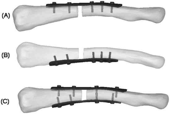
Figure 1.
4 mm fracture gap: (A) superior plate; (B) anteroinferior plate; (C) dual plate [15].
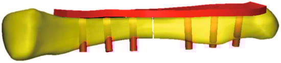
Figure 2.
0.5 mm fracture gap [15].
2.4. Boundary and Loading Conditions
Zhang et al. (2020) provide the necessary boundary and loading conditions to conduct similar research on clavicle fractures [15]. For the boundary conditions, the medial end of the clavicle was fixed, and a transverse fracture with a 4 mm gap was placed in the middle of the clavicle. A 100 N bending force, 100 N compressive force, and 1 N-m torsional force were studied for the loading conditions shown in Figure 3. Similarly, other studies using FEA to study the stress distribution of clavicle plate fixations used the same boundary and loading conditions. Other studies, such as Yurteri et al., Zhang et al. (2019), and Pengrung et al., use the same loading conditions of 100 N bending force, 100 N compressive force, and 1 N-m torsional force [6,14,17]. Cheng et al. use similar conditions but do not apply a torsional force; only a 100 N bending force and a 100 N compressive force are analyzed separately [7]. For this study, the loading conditions of 100 N bending force, 100 N compressive force, and 1 N-m torsional force are analyzed independently. The last loading condition is the combined load, where all are applied. The fixed medial end of the clavicle is, since the clavicle does not move on its medial end. The free lateral end allows the clavicle to move freely towards the shoulder in all directions, and the applied loads are designed to mimic the forces exerted by the shoulder’s movements on the clavicle. A physiological study on the actual shoulder forces during abduction and adduction resulted in a maximum Force of 126 N and 2.4 N-m torsional force, which supports the values used as loading conditions [18]. The boundary and loading conditions are meant to simulate the real-world loads carried by the clavicle roughly. However, the loads do not account for the reduced load experienced post-operation due to placement in the armrest. With this, the benchmark values are used to visualize stress distribution and understand bone and plate stress distributions, identifying which parts experience the majority of the stress.
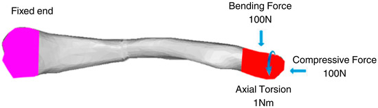
Figure 3.
Clavicle implant FEA boundary and loading conditions [15].
2.5. Research Design
This segment outlines the phases and steps necessary to achieve the study’s desired results shown in Figure 4. The study employs a three-phase design, comprising processing and development, simulation, and analysis. The specific details, including parameters and dimensions for model creation and processing, as well as the analysis methodology used to interpret the results, are provided.
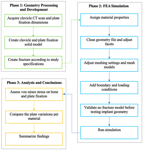
Figure 4.
Methodological framework of the study.
This study employs a quantitative approach, utilizing numerical analysis simulation with ANSYS FEA, to evaluate stress distribution in clavicle and plate fixation variations by analyzing the maximum von Mises stress. This section outlines the phases, steps, and specifics of the research methodology. The methodology follows a three-phase process that encompasses the generation of necessary geometry, FEA simulation, analysis, and drawing of conclusions. Each phase is segmented into specific steps that outline the process and parameters of this study, based on previous studies. Following this, the methodology covers research design, data collection and analysis methods, ethical considerations, limitations, and conclusions.
2.5.1. Phase 1: Geometry Processing and Development
The first phase of the methodology covers the processing and development of the necessary geometries. The geometries needed for this study are clavicle geometry, plate geometry, and the fracture gap model. Utilizing the methods and parameters from previous studies, the clavicle model is processed in a similar manner, using CT scans. Plate geometry is created using the provided standard parameters, and the fracture gap model is derived from parameters and recommendations of previous studies, as well as from pertinent articles regarding middle clavicle fractures. The phase output is geometries ready to be processed and meshed for FEA in the next phase. The clavicle model used in this study was obtained from a CT scan at Northern Mindanao Medical Center shown in Figure 5. The plate fixation model used in this study is based on the parameters provided by Yurteri et al., which is a standard pre-contoured S-plate with a length of 90 mm, a width of 10 mm, and a thickness of 3.5 mm [6]. The plate holes are designed to fit 3.5 mm cortical screws. The screws are modeled as cylinders to simplify geometry and meshing, following the method of Zeng et al. [19].
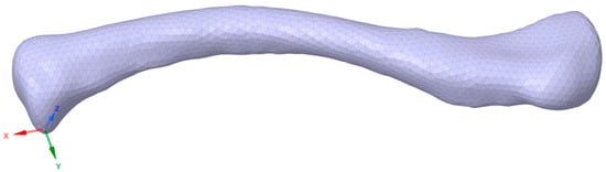
Figure 5.
Clavicle CT scan geometry.
With the clavicle CT scan acquired, it is processed in Ansys Spaceclaim using tools such as shrinkwrap and smoothen to fill holes and gaps shown in Figure 6. With the plate and screw specifications provided in the previous step, the model is generated in Fusion360 and imported into Ansys to fit the intact clavicle model. Four combined clavicle and plate fixation models are created according to the study specifications of Zhang et al. (2020): superior single plate (3.5 mm thickness), anteroinferior single plate (3.5 mm thickness), dual plate (1.6 mm), and dual plate (3.5 mm thickness on both plates) [15]. A CT scan model is utilized and modeled to a uniform 2 mm outer cortical bone, with the remaining inner part representing the cancellous bone, as described by Pengrung et al. [17]. For this study, a fracture line is used, similar to that of Yurteri et al., to ensure a uniform analysis method. The study by Yurteri et al. analyzed different materials by comparing the maximum von Mises stress on the plate, cortical bone, and the area of the fracture line. To apply the method of analysis, a fracture line model is used.
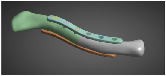
Figure 6.
Clavicle with implant model.
2.5.2. Phase 2: FEA Simulation
The second phase of the methodology covers all the steps in preparing and conducting the FEA simulation. The steps are aligned with the common steps for static structural analysis simulations. For material properties, the needed inputs are Young’s modulus and Poisson’s ratio; the other material properties are derived automatically from the two inputs. With the geometry created in the first phase, all the geometries are assembled in Ansys SpaceClaim. Utilizing a SubD geometry type reduced the number of facets, which facilitated the simulation. Element sizing is adjusted accordingly. The element sizes are reduced if errors occur due to incomplete meshing or if there are too many elements and nodes for the simulation to run. This study employs a 3 mm bone mesh size, similar to that used by Yurteri et al. [6], and a 1 mm plate mesh size shown in Figure 7. Reducing the size to less than 3 mm results in an error because some simulation setups exceed the allowable number of nodes and elements for the Ansys Student Version.
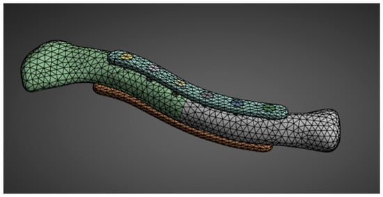
Figure 7.
Geometry meshing.
With the geometry already meshed, the necessary boundary and loading conditions are input shown in Figure 8. The boundary and loading conditions used are meant to simulate the real-world loads carried by the clavicle roughly. Before conducting the simulations, it was necessary to validate the FEA simulation model against existing studies to ensure that the parameters were correctly replicated. For this purpose, the study by Cao et al. was used to validate the simulation data for an intact clavicle [20]. Once the FEA simulation has been validated, run it with the parameters mentioned in the previous steps. For the solution, von Mises stress is assessed. The results are compiled and analyzed in the next phase, per material.
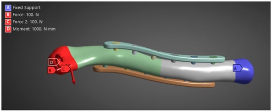
Figure 8.
Boundary and loading conditions.
2.5.3. Phase 3: Analysis and Conclusions
The final phase involves analyzing and drawing conclusions based on the simulation data obtained. The study aims to assess whether the implant material can withstand the loads of the clavicle with a 1 mm plate mesh and a 3 mm bone mesh. The stress distribution between plate and bone is evaluated to determine the possibility of stress shielding shown in Figure 9. Results are assessed per material based on implant failure and stress distribution between the plate and bone. Repeat the comparison of stress distribution between plate and bone to check whether there is a significant difference in stress distribution according to plate variation. The variations in stress distribution are assessed and categorized per material, and whether there are variations that indicate possible viability. The last step is to summarize the results and conclusions, indicating which materials and plate variations support the viability of their application in middle clavicle fractures. Additionally, suggest recommendations and improvements for future research.
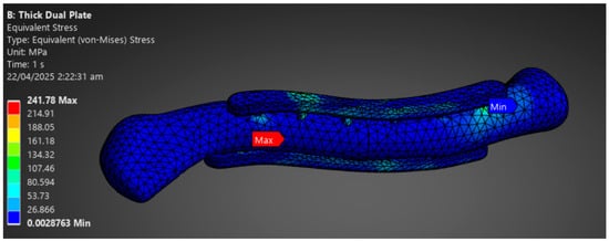
Figure 9.
Phase 3 Analysis Result Sample.
2.6. Validation
The validation section utilizes a previous FEA study on an intact clavicle bone. It is essential to test the results of an intact clavicle before proceeding to fracture models to gain insight into the differences in values, primarily due to the methodological differences. The percent difference enables future researchers to account for the systematic bias introduced by the methods used in this study. The percent difference ideally should be less than 10%. Still, since the settings for all materials and variations are consistent, the percentage of systematic error is also consistent, allowing comparisons to remain viable and accurate.
The results from Cao et al. and this study for an intact clavicle are within 5 MPa and around a 10% difference shown in Table 2 [20]. This demonstrates the successful replication of Cao et al.’s methods, validating simulation parameters for subsequent simulations [20]. The result of the axial load validation is over the ideal 10% range. Still, strict limits on biomechanical FEA are not applicable, as noted by Oefner et al. (2021, Section 3.2.2), “The specification of a tolerable maximum error value often depends on the specific study. Therefore, this checklist does not define a generally tolerable maximum error value, but the deviation must be quantified and sufficiently discussed [21].” This is because, in comparison of materials, the systematic bias will be the same as the parameters are the same, thus making the comparisons between each material and variation viable. Especially for complex simulations, higher errors are observed, as seen in the study by Zheng et al. (2015), which reported a 24% error attributed to the complexities of its anatomical model [22]. For this study, the 11.29% percent change is primarily attributed to the difference in geometry processing method and screw geometry. The study of Cao et al. utilizes MIMICS Medical software, while the current study adopts the method of Pengrung et al. that models the outside cortical bone as a 2 mm thick shell [17,20]. Furthermore, the study by Cao et al. utilizes an accurate screw model. In contrast, the current study employs an idealized cylindrical screw, similar to the one used by Zeng et al., as the screws are not analyzed in the present study [19,20]. With this, the percent error is slightly above the ideal 10% range due to the difference in geometry processing and screw geometry.
Table 2.
Present and Previous Study Validation of Maximum von Mises Stress Results.
2.7. Convergence Testing
A convergence test is conducted on bone and plate mesh similar to the study of Yurteri et al. [6]. The study of Yurteri et al. determined that the optimal sizes for mesh are 3 mm for bone mesh and 1.5 mm for plate mesh [6]. With this, this study tests bone mesh ranging from 4 mm to 2 mm in increments of 0.5 mm, with a constant plate mesh of 1 mm. A plate mesh convergence test is also performed, ranging from 2 mm to 0.75 mm in increments of 0.25 mm, with a constant bone mesh of 3 mm. The percent change is checked to ensure it is less than 10%, verifying that the values for Maximum von Mises Stress in MPa converge. The primary objective of the study was to conduct a comparative analysis of the stresses in different materials and plate variations. All models were analyzed under the same mesh settings and constraints. The relative differences between the various plate materials and variations remain valid, with a maximum 10% change limit on the convergence test.
Two convergence tests are performed, one for the bone mesh and another for the plate mesh. The convergence test is separated due to the difference in mesh sizing, with the plate mesh being finer than the bone mesh. The bone mesh sizing ranges from 4 mm to 2 mm, with a constant plate mesh of 1 mm is shown in Figure 10. The maximum von Mises stress values range from 189.18 MPa to 220.49 MPa, showing converging values within 10% of each other. The specific percent changes starting from 3.5 mm to 2 mm are 5.89%, 4.54%, 4.41%, and 6.78%. This indicates that the values converge, with all mesh sizes exhibiting percent changes of less than 10%. Following the initial mesh of Yurteri et al. (2024), a 3 mm bone mesh is used [6].
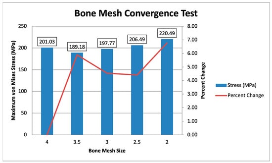
Figure 10.
Bone Mesh Convergence Test.
For the plate mesh convergence, the plate mesh size ranges from 2 mm to 0.75 mm, with a constant bone mesh size of 3 mm is shown in Figure 11. The maximum von Mises stress ranges from 161.53 MPa to 206.8 MPa, with the difference reducing as the mesh is finer. The specific percent changes, starting from 1.75 mm to 0.75 mm, are 14.92%, 6.78%, 4.36%, 9.50%, and 4.57%, showing that the mesh sizes from 1.5 mm to 0.75 mm converge, with all values being less than 10%. The initial plate mesh from Yurteri et al. (2024) is 1.5 mm, but a 1 mm plate mesh is used for this study for more accurate results, as the values converge [6].
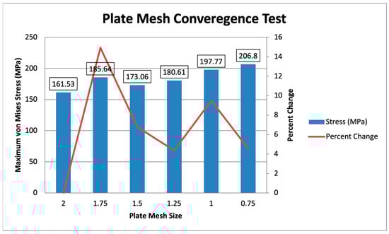
Figure 11.
Plate Mesh Convergence Test.
3. Results
3.1. Maximum von Mises Stress Results for All Materials and Variations
Table 3 shows the resulting stresses on the plates, lateral bone, medial bone, lateral fracture face, and medial fracture face per material and plate variation. The different plate variations are checked through convergence studies to ensure minimal stress concentrations. Remeshing and adjustment of mesh sizes are performed in the event of abnormalities to ensure accurate results. For the criteria used for viability by Yurteri et al., checking for greater plate stress is essential to indicate that the plate bears most of the weight, not the bone, and demonstrates sufficient material strength to support the loads of the clavicle [6]. Furthermore, checking for stress increases in the fracture line, such as those greater than 150 MPa, follows the yield strength of Cortical bone, which is around 120–150 MPa; stresses higher than this may indicate a higher likelihood of refracture, malunion, non-union, and other issues that will prevent bone from healing properly.
Table 3.
Maximum von Mises Stress in MPa.
3.2. Plate Stresses
Figure 12 illustrates the plate stresses for various materials and plate configurations. The maximum plate stress for metal (Titanium, Stainless Steel, Cobalt Chromium, and Magnesium) reaches up to 271.23 MPa. In comparison, the maximum stress of the polymers (PEEK and PLA) only reaches up to 168.13 MPa. This indicates that the metals can withstand more stress than the polymers. This can be attributed to the higher strength of the metals, which is significantly greater than that of the polymers, similar to the strength of bone. The higher stress distributions in the metals indicate a better ability to handle loads; however, it also means a higher likelihood of stress shielding. With this, the graph shows higher stresses for metals compared to polymers, indicating higher load-bearing capabilities but a higher likelihood for stress shielding.
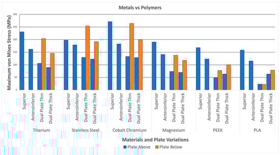
Figure 12.
Metals and Polymers.
3.3. Maximum von Mises Stress per Material
3.3.1. Titanium
Figure 13 illustrates the plate stresses, bone stresses, and fracture face stresses for various plate configurations using titanium material. All variations show greater maximum plate stress than maximum bone stress. Additionally, all variations exhibit fracture line stresses of less than 150 MPa, with the highest being 41.88 MPa in the superior variation. This indicates that Titanium shows viable use as it passes the two criteria. Furthermore, this supports the use of Titanium as an existing standard material.
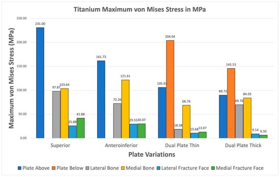
Figure 13.
Titanium Plate Fixation.
3.3.2. Stainless Steel
For Stainless Steel, all plate variations show greater maximum von Mises plate stresses compared to bone stresses shown in Figure 14. The fracture line stresses are also significantly below 150 MPa, reaching a maximum of 35.728 MPa, with the superior variation. These results demonstrate the viability of Stainless Steel plate fixations and support its use as a standard material for orthopedic implants.
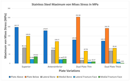
Figure 14.
Stainless Steel Plate Fixation.
3.3.3. Cobalt Chromium
Cobalt Chromium consistently shows higher maximum von Mises plate stresses relative to bone stresses for all variations seen in Figure 15. The fracture line stresses are also all safely below the 150 MPa limit, with the highest at 34.88 MPa, and exhibit the highest variation. The results confirm the viability of Cobalt Chromium, but the likelihood of stress shielding is high, as most of the stress is covered by the implant.
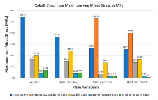
Figure 15.
Cobalt Chromium Plate Fixation.
3.3.4. Magnesium
Magnesium alloy demonstrates higher maximum von Mises stresses for the plate compared to the bone through all plate variations shown Figure 16. The fracture line stresses are also well below the 150 MPa limit at a peak of 55.798 MPa for the superior variation. The different variations demonstrate viability, but the anteroinferior variation exhibits the highest plate and bone maximum von Mises stress, suggesting that it is the least favorable variation for Magnesium.
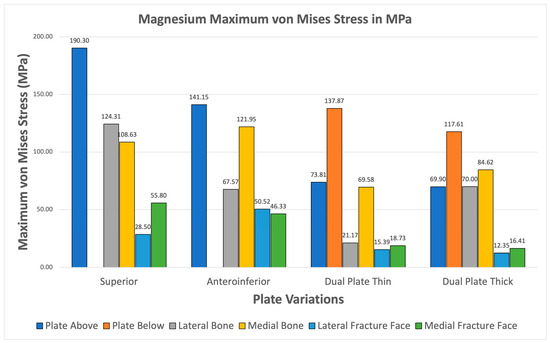
Figure 16.
Magnesium Plate Fixation.
3.3.5. PEEK
All PEEK plate variations exhibit higher maximum von Mises plate stress than bone stress shown in Figure 17. Fracture line stresses are also all below 150 MPa, with the highest at 88.471 MPa, and show the greatest variation. Notably, the maximum von Mises stress for bone and plate are close to each other, primarily attributed to PEEK’s mechanical properties being similar to bone. This raises concerns about its strength, but it still meets both criteria, demonstrating its viability.
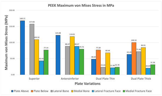
Figure 17.
PEEK Plate Fixation.
3.3.6. PLA
The PLA variations ultimately fail the viability criteria, with only the superior variation achieving higher maximum von Mises stress for the plate over bone shown in Figure 18. Fracture line stresses are all below 150 MPa but near the limit, with a maximum of 146.39 MPa for the anteroinferior variation, with the superior variation following closely. With this, PLA does not show viable use as it fails the first criterion and approaches the limit with the second criterion. Although the results do not indicate viable use, the superior and thick dual plate variations exhibit better performance, with plate and bone stress being similar, and low fracture line stresses observed in the thick dual plate variations.
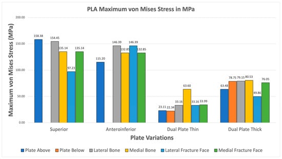
Figure 18.
PLA Plate Fixation.
3.4. Fracture Line Stresses
Figure 19 shows the lateral and medial fracture line stresses grouped per plate variation. The graph illustrates the difference between single-plate and dual-plate variations. The dual plate variations show consistently lower fracture line stresses as compared to the single plate variations. The thick dual plate variation has the least fracture line stresses, except for the PEEK and PLA materials, which show an increase in fracture line stress. With this, the dual plate variations provide more stability, resulting in lower fracture line stress and a reduced risk of refracture, malunion/non-union, and implant failure at the fracture line.
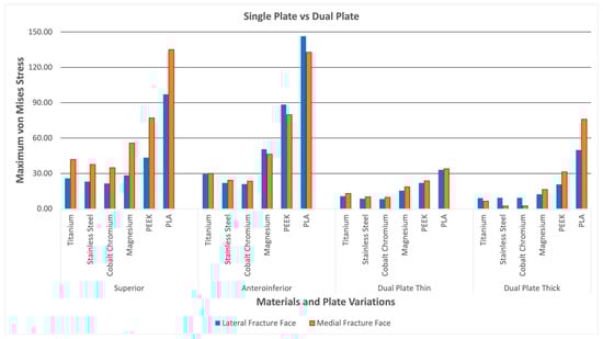
Figure 19.
Dual Plate and Single Plate.
3.5. Material Failure Analysis
Table 4 shows the maximum plate stress and yield strength alongside the computed safety factor. Although material failure is uncommon for implants, common causes include refracture or non-union at the fracture, which occurs before the material breaks. It is still worth exploring whether stresses exceed yield strength. From the results, it can be seen that Titanium, Stainless Steel, Cobalt Chromium, and Magnesium exhibit maximum stresses below their yield strengths. Titanium, Stainless Steel, and cobalt chromium exhibit safety factors greater than 1.5, indicating a low risk of material failure. Magnesium exhibits safety factors of approximately 1.5, except for the superior variation, which is near one, suggesting a potential risk of material failure for this variation. For PEEK, the superior variation maximum stress exceeds the yield strength, which indicates that it may not have sufficient material strength to support the induced stress. The dual plate variations for PEEK have higher safety factors, indicating a lower risk associated with these plate variations. However, the anteroinferior variation, even with maximum stress less than yield strength, has a safety factor of almost 1, indicating a risk for material failure or insufficient strength. For PLA, both superior and anteroinferior variations have maximum stresses greater than yield strengths, indicating insufficient strength. The dual plate variations for PLA, on the other hand, have higher safety factors, indicating the potential ability to sustain clavicle loads. Overall, the metals demonstrated sufficient material strength, while the polymers exhibited limited strength for superior and anteroinferior variations, as well as lower risks for dual plate variations.
Table 4.
Material Failure Analysis.
4. Discussion
4.1. Material Viability
Table 5 displays the various clavicle plate materials and their corresponding variations, including whether they meet the first and second criteria, and whether their maximum plate stresses do not exceed the yield strengths of the materials. Criteria 1, as previously discussed, is whether the maximum von Mises stress on the plate is greater than the maximum von Mises stress on bone. In contrast, criteria 2 is if the maximum von Mises stress on the fracture line is less than 150 MPa. The materials Titanium, Stainless Steel, Cobalt Chromium, and Magnesium all passed the two criteria and did not exceed their yield strengths. This indicates the possible viability of Titanium, Stainless Steel, Cobalt Chromium, and Magnesium as clavicle plate fixations for all four tested variations. For PEEK, the anteroinferior and dual plate variations passed the two criteria. They did not exceed the yield strength, but the superior variation exceeded the yield strength, which indicates possible insufficient strength to handle the induced stress. For PLA, only the superior variation met both criteria and exceeded the yield strength of the other variations. Not all PLA plate variations are suitable for use, as their bone stresses exceed plate stress, and maximum stresses exceed the yield strength, indicating a high risk of material failure due to insufficient strength. With this, Titanium, Stainless Steel, Cobalt Chromium, Magnesium, and PEEK demonstrate viability as alternatives to clavicle plates for all variations except the PEEK superior variation. PLA, on the other hand, is not a viable alternative for all plate variations.
Table 5.
Viability Overview.
4.2. Material Behavior
The findings demonstrated how various materials behave mechanically when subjected to clavicular loads. When compared to bone, the metals titanium, stainless steel, and cobalt chromium demonstrated superior mechanical properties through high plate stresses, suggesting that these materials can withstand the majority of the stress. These findings are consistent with the materials’ high yield strengths and modulus of elasticity. Magnesium alloy and PLA, two bioabsorbable materials, demonstrated varying outcomes; PLA outperformed in terms of yield strength and showed insufficient strength to sustain clavicular stresses. In contrast, the magnesium alloy demonstrated exceptional strength and performance under higher stresses, even at stresses below its yield strength, suggesting that it is a feasible material. PEEK failed in the superior plate variation because it exceeded the yield strength, despite meeting the first condition of higher plate stresses and limited stress in the fracture line. While Magnesium and PEEK showed viability but lower safety factors, PLA demonstrated that it is not viable. Overall, Titanium, stainless steel, and cobalt chromium exhibited viability with high safety factors.
4.3. Comparison to Literature
The comparison to literature section compares the current study’s results with those of previous studies to highlight what the data reinforce and what contradicts previous findings shown in Table 6. The primary previous studies covered are those of Yurteri et al., Cheng et al., and Zhang et al. because of the similar materials and plate variations covered [6,7,15].
Table 6.
Present and Previous Study Findings.
The findings of this study are aligned with previous literature regarding specific materials. The findings of this study regarding the viable use of PEEK align with those of Yurteri et al., who tested materials including PLA, PLA/HA, and PEEK. This study, as well as the study by Yurteri et al., both find PEEK to be a viable alternative and PLA to be not feasible [6]. However, the study of Yurteri et al. finds the superior plate variation viable. Still, this study finds that it has a risk of material failure due to exceeding its yield strength shown in Figure 20 [6]. This difference in findings is due to the inclusion of yield strengths as additional criteria in this study, which are not present in the study by Yurteri et al. [6]. For Magnesium, Cheng et al. (2021) studied the stiffness of magnesium plates and found it to be viable due to its similarity in stiffness to bone [7]. This study reinforces its viability through providing context on its stress distribution and by the material passing all the criteria shown in Figure 21. For the plate variations, the study by Zhang et al. (2020) examined single and dual plate variations using Titanium material and found no significant difference between the plate variations [15]. This study demonstrates a difference in stability between single-plate and dual-plate variations, as evidenced by their differences in fracture line stresses. Specifically, dual plate variations exhibit significantly lower fracture stress, indicating improved stability and a reduced risk of refracture.
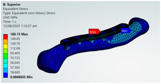
Figure 20.
PEEK Superior Plate Fixation, Maximum von Mises Stress Exceeding 125 MPa yield strength limit.
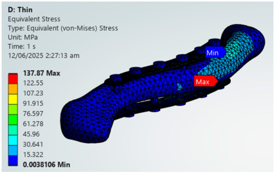
Figure 21.
Magnesium Thin Dual Plate Variations.
5. Conclusions
In order to evaluate the feasibility of various materials as alternatives for clavicle plate fixation, as well as variations in plate thickness, this study conducted FEA using ANSYS. Titanium, stainless steel, cobalt chromium, Magnesium, PEEK, and PLA were the six materials used in the study. There were four types of these materials: superior, anteroinferior, thin dual, and thick dual. Three criteria were used to test each material: (1) the maximum von Mises stress on the plate was larger than the maximum von Mises stress on the bone; (2) the stress at the fracture line was less than 150 MPa; and (3) the maximum von Mises plate stress was less than the yield stress. According to the study’s findings, all plate modifications for Titanium, stainless steel, cobalt–chromium, and magnesium alloys were consistently viable. The study also supports the use of common materials, such as stainless steel and Titanium, as well as substitutes, including magnesium alloy and cobalt chromium, for all variations. For every variant, polyether ether ketone (PEEK) demonstrated initial viability. It may be appropriate for lower load applications for Anteroinferior, thin dual plate, and thick dual plate variations; however, it failed the yield strength test for the superior variation. The superior plate is placed on top of the clavicle or the tension side, far from the neutral axis; therefore, the resulting stress is higher compared to other variations. Because of how the plate is positioned, it is subjected to relatively higher tensile and compressive stresses, concentrating stress on screw holes. The findings demonstrated that, due to its insufficient material strength, polylactic acid (PLA) is not feasible for all variations. All materials exhibited consistently lower fracture line stresses in the thin dual plate and thick dual plate versions of the plate. The findings of Zhang et al. (2019), who found no discernible difference between plate variants, may have been influenced by their study’s exclusive focus on Titanium [14], in contrast to our outcome. Like Yurteri et al.’s study [6], this study also supports the idea of comparing plate stress and bone stress as indicators of stress shielding. The PEEK and PLA results are identical to those of Yurteri et al., who concluded that PLA is insufficient for this application. Although PEEK exhibits intriguing potential, this work concludes that the superior plate variation is unsafe, as its maximum stress exceeds the yield stress (a requirement that Yurteri et al. did not verify) [6]. Notwithstanding the study’s software limitations, it offers a reproducible and precise methodology that other researchers with comparable constraints can utilize, enabling the efficient, correct, and significant conduct of orthopedic research.
Based on the results of this study, several recommendations for future research are proposed. First, for materials, Titanium and Stainless Steel are reinforced as standard materials due to their excellent material strength; however, their high Young’s modulus is a concern for stress shielding. Cobalt Chromium provides outstanding strength and stability, making it suitable for patients who require early weight-bearing movements after surgery; however, the likelihood of stress shielding is high. Magnesium alloy exhibits excellent material strength, complemented by its bioabsorbability, which eliminates the need for removal surgery; however, further clinical studies are necessary. Similarly, PEEK shows potential application, but with the plate and bone stresses near each other, low-load applications are advised, along with further clinical studies. PLA does not show viability; further studies on PLA composites, such as PLA/HA, which have greater material strength, may be conducted in future studies. For plate variations, dual plate variations showed reduced fracture line stresses, making them better suited for applications requiring stability, such as comminuted or unstable fractures. Furthermore, superior variations resulted in higher stresses, which require higher-strength materials to limit risks. A full ANSYS license along with medical imaging software is recommended for future researchers to explore other functions, such as fatigue behavior, degradation, and 3D printing imperfections. For laboratories and research institutions with higher medical access, clinical validation of the results of this study will further strengthen the use of bioabsorbable materials and other alternatives for clavicle plate fixation materials.
Author Contributions
Conceptualization, L.E.P.R.; Methodology, L.E.P.R.; Software, L.E.P.R.; Validation, L.E.P.R.; Formal analysis, L.E.P.R.; Investigation, L.E.P.R.; Resources, L.E.P.R.; Data curation, L.E.P.R.; Writing—original draft, L.E.P.R.; Writing—review and editing, L.E.P.R.; Visualization, L.E.P.R.; Supervision, J.P.H.; Project administration, L.E.P.R. and J.P.H.; Funding acquisition, J.P.H. All authors have read and agreed to the published version of the manuscript.
Funding
This research received no external funding.
Data Availability Statement
The original contributions presented in this study are included in the article. Further inquiries can be directed to the corresponding author.
Conflicts of Interest
The authors declare no conflict of interest.
Abbreviations
The following abbreviations are used in this manuscript:
| FEA | Finite Element Analysis |
| CT | Computed Tomography |
| PLA | Polylactic Acid |
| PEEK | Polyether Ether Ketone |
| MPa | Megapascal |
| Nm | Newton-Meter |
| S-Plate | Superior Plate |
References
- Bentley, T.P.; Hosseinzadeh, S. Clavicle Fractures. StatPearls. 2025. Available online: https://www.ncbi.nlm.nih.gov/books/NBK507892/ (accessed on 20 July 2025).
- Barber, C.C.; Burnham, M.; Ojameruaye, O.; McKee, M.D. A systematic review of the use of Titanium versus stainless steel implants for fracture fixation. OTA Int. 2021, 4, e138. [Google Scholar] [CrossRef] [PubMed]
- Wijdicks, F.-J.; Houwert, M.; Dijkgraaf, M.; de Lange, D.; Oosterhuis, K.; Clevers, G.; Verleisdonk, E.-J. Complications after plate fixation and elastic stable intramedullary nailing of dislocated midshaft clavicle fractures: A retrospective comparison. Int. Orthop. 2012, 36, 2139–2145. [Google Scholar] [CrossRef] [PubMed]
- Li, Z.; Khor, K.A. Preparation and properties of coatings and thin films on metal implants. In Encyclopedia of Biomedical Engineering; Narayan, R., Ed.; Elsevier: Amsterdam, The Netherlands, 2019; pp. 203–212. [Google Scholar] [CrossRef]
- Safavi, S.; Yu, Y.; Robinson, D.L.; Gray, H.A.; Ackland, D.C.; Lee, P.V.S. Additively manufactured controlled porous orthopedic joint replacement designs to reduce bone stress shielding: A systematic review. J. Orthop. Surg. Res. 2023, 18, 42. [Google Scholar] [CrossRef] [PubMed]
- Yurteri, A.; Mercan, N.; Uğur, L. Comparison of the use of biocompatible materials and Titanium in the treatment of midshaft clavicle fractures with a patient-specific plate: A finite element analysis study. Arch. Orthop. Trauma Surg. 2024, 144, 3255–3266. [Google Scholar] [CrossRef] [PubMed]
- Cheng, R.; Jiang, Z.; Dimitriou, D.; Gong, W.; Tsai, T.-Y. Biomechanical analysis of personalised 3D-printed clavicle plates of different materials to treat midshaft clavicle fractures. J. Shanghai Jiaotong Univ. Sci. 2021, 26, 259–266. [Google Scholar] [CrossRef]
- Nazzal, A.; Lozano-Calderón, S.; Jupiter, J.B.; Rosenzweig, J.S.; Randolph, M.A.; Lee, S.G.P. A histologic analysis of the effects of stainless steel and titanium implants adjacent to tendons: An experimental rabbit study. J. Hand Surg. 2006, 31, 1123–1130. [Google Scholar] [CrossRef] [PubMed]
- Zhu, Y.; Hu, J.; Zhan, T.; Zhu, K.; Zhang, C. Refracture after plate removal of midshaft clavicle fractures after bone union-incidence, risk factors, management, and outcomes. BMC Musculoskelet. Disord. 2023, 24, 308. [Google Scholar] [CrossRef] [PubMed]
- Chen, A.; Kurmis, A.P. Understanding immune-mediated cobalt/chromium allergy to orthopaedic implants: A meta-synthetic review. Arthroplasty 2024, 6, 1. [Google Scholar] [CrossRef] [PubMed]
- Hasanzadeh, R.; Mihankhah, P.; Azdast, T.; Rasouli, A.; Shamkhali, M.; Park, C.B. Biocompatible tissue-engineered scaffold polymers for 3D printing and their application for 4D printing. Chem. Eng. J. 2023, 476, 146616. [Google Scholar] [CrossRef]
- Wang, N.; Yang, S.; Shi, H.; Song, Y.; Sun, H.; Wang, Q.; Tan, L.; Guo, S. Magnesium alloys for orthopedic applications: A review on the mechanisms driving bone healing. J. Magnes. Alloys 2022, 10, 3327–3353. [Google Scholar] [CrossRef]
- Narayanan, G.; Vernekar, V.N.; Kuyinu, E.L.; Laurencin, C.T. Poly(lactic acid)-based biomaterials for orthopaedic regenerative engineering. Adv. Drug Deliv. Rev. 2016, 107, 247–276. [Google Scholar] [CrossRef] [PubMed]
- Zhang, X.; Cheng, X.; Yin, B.; Wang, J.; Li, S.; Liu, G.; Hu, Z.; Wu, W.; Zhang, Y. Finite element analysis of spiral plate and Herbert screw fixation for treatment of midshaft clavicle fractures. Medicine 2019, 98, e16898. [Google Scholar] [CrossRef] [PubMed]
- Zhang, F.; Chen, F.; Qi, Y.; Qian, Z.; Ni, S.; Zhong, Z.; Zhang, X.; Li, D.; Yu, B. Finite element analysis of dual small plate fixation and single plate fixation for treatment of midshaft clavicle fractures. J. Orthop. Surg. Res. 2020, 15, 148. [Google Scholar] [CrossRef] [PubMed]
- American Elements. Cobalt Chromium Alloy. Available online: https://www.americanelements.com/cobalt-chromium-alloy (accessed on 20 July 2025).
- Pengrung, N.; Lakdee, N.; Puncreobutr, C.; Lohwongwatana, B.; Sa-Ngasoongsong, P. Finite element analysis comparison between superior clavicle locking plate with and without screw holes above fracture zone in midshaft clavicular fracture. BMC Musculoskelet. Disord. 2019, 20, 465. [Google Scholar] [CrossRef] [PubMed]
- Hoogervorst, P.; Bolsterlee, B.; Pijper, M.; Aalsma, A.M.M.; Verdonschot, N. Forces acting on the clavicle during shoulder abduction, forward humeral flexion, and activities of daily living. Clin. Biomech. 2019, 69, 79–86. [Google Scholar] [CrossRef] [PubMed]
- Zeng, L.; Wei, H.; Liu, Y.; Zhang, W.; Pan, Y.; Zhang, W.; Zhang, C.; Zeng, B.; Chen, Y. Titanium elastic nail (TEN) versus reconstruction plate repair of midshaft clavicular fractures: A finite element study. PLoS ONE 2015, 10, e0126131. [Google Scholar] [CrossRef] [PubMed]
- Cao, R.; Tan, J.; Zhang, Y.; Dai, Y.; Zhang, X.; Han, X.; Jiang, X. Finite element analysis of antegrade and retrograde internal intramedullary nailing for mid-shaft clavicle fracture. BMC Musculoskelet. Disord. 2025, 26, 172. [Google Scholar] [CrossRef] [PubMed]
- Oefner, C.; Herrmann, S.; Kebbach, M.; Lange, H.-E.; Kluess, D.; Woiczinski, M. Reporting checklist for verification and validation of finite element analysis in orthopedic and trauma biomechanics. Med. Eng. Phys. 2021, 90, 25–32. [Google Scholar] [CrossRef] [PubMed]
- Zheng, J.; Shen, J.; Zhao, Y.; Chen, Z.; Wang, Y.; Yang, C.; Du, X.; Qiu, G. Construction and validation of a three-dimensional finite element model of adolescent idiopathic scoliosis spine. J. Orthop. Surg. Res. 2015, 10, 189. [Google Scholar]
- ASM. Material Data Sheet. Available online: https://asm.matweb.com/search/specificmaterial.asp?bassnum=mtp641 (accessed on 20 July 2025).
- Ulbrich. 316LVM Stainless Steel UNS S31673. Available online: https://www.ulbrich.com/alloys/316lvm-stainless-steel-uns-s31673/ (accessed on 20 July 2025).
- ARCAM. ASTM F-75 Cobalt Chrome Alloy. Available online: https://www.matweb.com/search/datasheet_print.aspx?matguid=df8d3cd30d5149cfaca9a3c6e3268655 (accessed on 20 July 2025).
- AZoM. Magnesium AZ31B Alloy (UNS M11311). Available online: https://www.azom.com/article.aspx?ArticleID=6707 (accessed on 20 July 2025).
- MatWeb. Overview of Materials for Polyetheretherketone, Unreinforced. Available online: https://www.matweb.com/search/datasheet_print.aspx?matguid=2164cacabcde4391a596640d553b2ebe (accessed on 20 July 2025).
- MatWeb. Overview of Materials for Polylactic Acid (PLA) Biopolymer. Available online: https://www.matweb.com/search/DataSheet.aspx?MatGUID=ab96a4c0655c4018a8785ac4031b9278&ckck=1 (accessed on 20 July 2025).


Disclaimer/Publisher’s Note: The statements, opinions and data contained in all publications are solely those of the individual author(s) and contributor(s) and not of MDPI and/or the editor(s). MDPI and/or the editor(s) disclaim responsibility for any injury to people or property resulting from any ideas, methods, instructions or products referred to in the content. |
© 2026 by the authors. Licensee MDPI, Basel, Switzerland. This article is an open access article distributed under the terms and conditions of the Creative Commons Attribution (CC BY) license.