Abstract
To study the mechanical response of the joint under the lateral synergistic action of articulated assembled subgrade, and to screen out the joint materials with the best suitability, this paper establishes a finite element model of an articulated, assembled base-layer asphalt pavement using ABAQUS. It analyses the influence of articulated reinforcement, structural layer, and material parameters on the mechanical response of the joint. The results show that the articulated reinforcement effectively inhibits the displacement of the slab so that the vertical compressive stress at the bottom of the joint decreases by about 37%; the extreme value variation in the modulus of the surface layer, subgrade layer, and soil base causes the principal stress to decrease by about 0.26%, 5.5%, and 11.6%, respectively; the increase in the thickness of the surface layer and the subgrade layer effectively improves the stress state, with a maximum reduction of 9% and 22%, respectively; Poisson’s ratio and modulus of elasticity of the joint material have a significant effect on the principal stress, and when the material parameters are at the maximum value, the principal stress increases by about 20.8%. In addition, this paper proposes a screening standard for joint material. Finally, it selects 60 mesh rubber-modified asphalt as the optimal joint material.
1. Introduction
Traditional semi-rigid subgrade asphalt pavement is affected by both the construction process and the material itself during the molding process [1,2,3], resulting in a significant coefficient of rise and shrinkage, poor volumetric stability, and susceptibility to shrinkage cracks [4,5,6]. Therefore, the assembled subgrade road with the core concept of assembled construction came into being, which has the significant advantages of high construction efficiency [7,8], controllable quality [9], low environmental impact [10,11,12], and low maintenance cost [13,14,15]. The subgrade of the assembled road consists of concrete slabs and joints, in which the joints, as the key parts of assembled roads, are susceptible to environmental changes. With the change in temperature and humidity, the joint gap is in the alternating state of expansion and contraction, resulting in the asphalt layer in the joint withstanding the alternating tensile and compressive stresses, which easily trigger the infiltration of road surface water or intrusion of complex objects, leading to the expansion of the joint being blocked, resulting in the joint fragmentation, the bottom of the plate hollowing, and other road hazards. When the traffic load is applied to both sides of the joint, the concrete slabs are prone to large displacements, and the asphalt layer is subjected to shear stresses at the joint, which can easily induce load-type reflective cracks [16,17,18,19,20].
For the prevention and control of various types of reflection cracks, structural optimization of the road subgrade is the mainstream of today’s research. Scholars have proposed various effective prevention and control measures, such as setting up a stress-absorbing layer, increasing the thickness of the paving layer, and adding a cover layer [21,22,23]. For example, a novel cover strategy was designed, and a multi-layer cover structure was constructed to reduce the occurrence of reflection cracks [24,25]. On this basis, researchers have established a road inspection system covering structural integrity and bearing capacity by combining the existing structural layer parameters. This further provides a new assessment method to optimize the anti-reflective cracking performance of asphalt pavements [26]. In addition, asphalt modification, a common technique to enhance the durability of pavements, has been widely used in road engineering [27,28,29]. Relevant studies have shown that incorporating modified materials, such as crumb rubber (CR) and basalt fibers, can significantly delay the generation of reflection cracks and effectively improve the crack resistance of asphalt [30,31,32].
To prevent and control different types of reflective cracks, scholars have proposed various surface structure optimization schemes, such as setting up stress-absorbing layers and adding cover layers [33,34]. However, the assembled road structure is made of prefabricated modules, which have a large number of joints and complex structures compared with monolithic paving, and it is difficult for conventional surface structure optimization schemes to solve such systematic structural defects [35,36]. Therefore, scholars started from the source of the joint and designed new connection forms, such as pre-stressed mortise and tenon joints, which significantly improved node-bearing capacity and crack resistance [37]. On this basis, some scholars carried out long-term monitoring, which was used to confirm that high-quality joint design can effectively inhibit the development of reflection cracks and extend the service life of pavements [38]. In addition, under the combined effect of environmental factors and vehicle loads, joint materials are more likely to undergo more significant deformation than concrete slabs, resulting in stress concentrations in the asphalt surface layer at the joint, exacerbating the formation of reflection cracks. Therefore, the performance of joint materials has a decisive influence on load transfer, synergistic stress, and anti-reflective cracking ability in assembled roads [39,40]. Research on joint materials mainly focuses on semi-rigid base asphalt pavements and precast asphalt bridge decks. Scholars usually use different types of joint materials to enhance the overall stress performance of the components, such as asphalt emulsion [41], epoxy asphalt mastic (EAM) [42], SBS-modified rubberized asphalt [43], and void-reducing asphalt membrane material (VRAM) [44].
Although existing research has extensively explored the structural optimization of assembled subgrades, particularly in terms of laying schemes, connection forms, and the application of jointing materials, the following research gaps still exist:
- (1)
- There is a lack of research on the mechanical response of joints under the lateral synergistic action of assembled subgrade.
- (2)
- How to select high-performance joint materials to improve the resistance of articulated assembled subgrade asphalt pavements to reflective cracking.
Aiming at the above problems, this paper analyses the influence of articulated reinforcement on the force of assembled road joints based on the ABAQUS finite element model of articulated assembled grass-roots level asphalt pavement and explores the change rule of the structural layer and the material parameters of the joint on the mechanical response of the joint. Meanwhile, as an important part of the assembled subgrade, the anti-reflective crack performance of joints is crucial for road smoothness and traffic safety. To promote the resourcefulness of waste rubber tyres and improve the performance of grouting asphalt, this paper selects waste tyre rubber powder with different mesh sizes as the modifier, selects the rubber-modified asphalt with the best performance as the joint material throughout the test, and verifies the use effect in combination with the actual project. The study aims to explore the impact of steel articulation on the mechanical properties of assembled subgrade joints, put forward the screening criteria for joint materials, and screen out the joint materials suitable for articulated assembled subgrade to provide theoretical support for practical engineering applications.
2. Experimental Design
2.1. Raw Materials
In this paper, the matrix asphalt used is Qilu Petrochemical 70#, a road petroleum asphalt, with its specifications listed in Table 1. The rubber powder used in this paper is produced from waste tyre rubber powder by Shanxi Hongrui Rubber Products Factory; its technical indicators are shown in Table 2.

Table 1.
Technical index of Qilu Petrochemical 70# matrix asphalt.
Table 2.
Technical specifications of tyre rubber powder.
2.2. Test Methods
2.2.1. Preparation of Rubber-Modified Asphalt
To compare the effect of different meshes on the performance of asphalt, in the case where other test conditions are the same, different meshes of rubber powder (rubber powder mixing amount of 15%) were selected and added to the matrix asphalt (this paper selects 20 mesh, 60 mesh, 100 mesh). A specific rubber-modified asphalt preparation flow chart is shown in Figure 1.
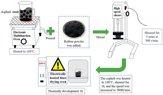
Figure 1.
Flow chart of rubber-modified asphalt preparation.
2.2.2. Performance Pilot Test
The purpose of this test is to study the modification of asphalt by rubber powder with different mesh sizes; to compare the performance differences between the three different mesh sizes of rubber-modified asphalt and the base asphalt by carrying out the penetration test, the softening point test, the ductility test, and the Brinell’s rotational viscosity test (27# rotor was used in this test, and the rotational speed was 20 r/min. The temperatures were selected to be 135 °C, 155 °C, and 175 °C); and to select the best assembly base joint material. The test process diagram is shown in Figure 2.
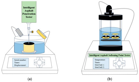
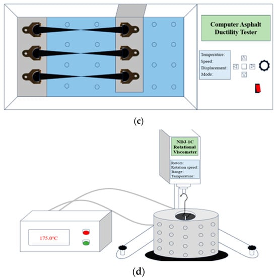
Figure 2.
Asphalt test process: (a) penetration test, (b) softening point test, (c) ductility test, and (d) Brinell’s rotational viscosity test.
2.3. ABAQUS Structural Model
Assembled base asphalt pavement is an innovative structure formed using prefabricated components and materials combined with traditional asphalt pavement technology. Unlike traditional asphalt pavements, assembled subgrade asphalt pavements adopt precast concrete panels and asphalt caulking technology in the subgrade, significantly improving the construction efficiency and the pavement service life through modular design and construction methods. Its main structural layers include an asphalt surface layer, an assembled subgrade, a gravel leveling layer, and a soil subgrade. As the core part of the technology, the assembled subgrade accelerates the construction process and makes the pavement superior in bearing capacity and crack resistance. The subgrade slab, assembled subgrade structure, joint model, and articulated model are shown in Figure 3.
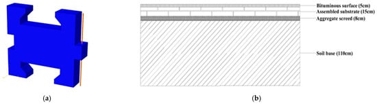
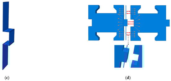
Figure 3.
Schematic diagram of subgrade slab, assembled subgrade structure, joint model, and articulated model. (a) Subgrade slab; (b) assembled subgrade structure; (c) joint model; (d) articulated model.
2.3.1. Road Structure Parameters
The asphalt surface layer selected AC-13 asphalt mixture, the assembled grass-roots level consists of asphalt and concrete slabs, the gravel leveling layer selected mixed grain size gravel, and the soil layer is dense soil. The Concrete Damage Plasticity (CDP) model was selected as the structural model for cementitious materials when simulating road structural parameters. This choice stems primarily from its ability to effectively capture the nonlinear behavior and damage mechanisms of materials under complex loading conditions, adapt to diverse loading scenarios, and due to the fact that it has been validated through extensive research and engineering applications. Furthermore, parameter acquisition for this model is relatively straightforward, and calibration using experimental data enhances simulation accuracy and credibility. This provides a robust theoretical foundation for road design and performance evaluation.
Joint material selection of different types of asphalt for comparison (due to the standard asphalt types of density not being much different, the density of this paper is uniformly set to 1.1 g/cm3). The pavement structural layer material parameter table and joint material parameter table are shown in Table 3 and Table 4.
Table 3.
Structural layer material parameter and thickness.
Table 4.
Joint material parameter.
2.3.2. Exposure Condition
Due to the special characteristics of this pavement structural model’s subgrade, which consisted of a concrete slab and caulking together, there was normal contact and tangential contact between them. To better fit with the actual pavement, penalty function contact and Tie binding were set between each structural layer of the pavement, i.e., there was a finite slip between each structural layer of the model, or each structural layer was fixed. The contact table for each structural layer is shown in Table 5.
Table 5.
Structural layer contact.
2.3.3. Boundary Condition
In the boundary condition setting, the bottom surface of the soil foundation is set as a fixed surface, and the displacement of the model along both sides of the traveling direction in the x-direction was restricted. The boundary condition settings are shown in Figure 4.
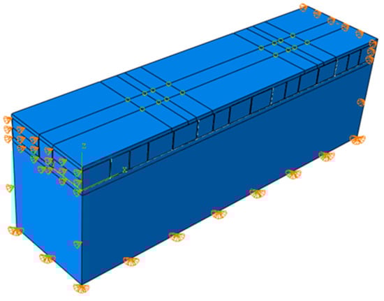
Figure 4.
Schematic diagram of boundary condition.
The hexahedral mesh C3D8R was used for the delineation in the meshing. The mesh was encrypted at critical locations, as shown in Figure 5, to ensure the accuracy of the mechanical response around the loading location. Table 6 shows the specific meshing of each structural layer.
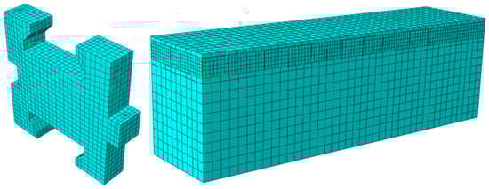
Figure 5.
Schematic diagram of grid division.
Table 6.
Structural layer meshing.
2.3.4. Pavement Loading Method
The type of pavement loading specified was a standard axle load of BZZ-100, consisting of a single axle and two wheelsets, with the ground pressure precisely set at 0.7 MPa. The specific locations of the loads covered several critical areas of the asphalt surface layer, i.e., the middle of the slab, the edge of the slab, and the part corresponding to the corners of the slab. To simplify the analysis process, the load was rationally reduced to a double-circle homogeneous load model. During the calculation process, specific formulas must be applied to determine the equivalent circular diameter of the bicircular load to more accurately assess its impact on the pavement.
In the formula:
—Acting on the wheel load (KN), our standard axle load BZZ-100 = 100/4 = 25 KN;
—Tyre contact pressure (KPa), take the value of = 700 KPa.
In this paper, to facilitate the ABAQUS mesh division and calculation and take into account the actual condition of the wheel load, the form of load application was simplified to a rectangle, with a length and width of 0.2 m, a distance between the centers of the two wheels of 0.3 m, and a distance between the wheels of 1.8 m, as shown in Figure 6.
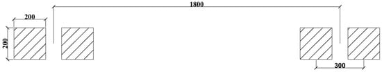
Figure 6.
Load schematic (mm).
3. Analysis of Test Results
3.1. Mechanical Properties Analysis of Joint
3.1.1. Performance Analysis of Joint Articulation
In assembled base asphalt pavement structures, the articulation of joints plays a crucial role in the overall pavement performance, especially in delaying the formation of reflection cracks. The core of the design of the articulated assembled subgrade structure lies in enhancing the cooperative interaction between the panels by optimizing the articulation performance in the joint area. The mechanical behavior at the joint can be made more stable through the reasonable selection of joint materials and connection methods, thus reducing the stress concentration phenomenon in the joint. To enhance the robustness of the connection, this paper establishes a conventional embedded extruded assembled subgrade model using ABAQUS software (v.Abaqus 2023). It selects the mechanical connectors (steel reinforcing bar) to connect the plate junctions in series, thereby optimizing the articulation of load transfer in the joint, as shown in Figure 7.
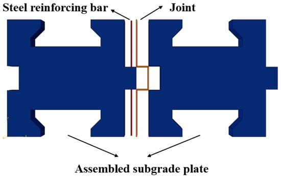
Figure 7.
Reinforcing bar series articulation diagram.
The force changes in the indirect joint of subgrade slabs under the action of reinforcing steel articulation show a complex mechanical response. Rebar articulation influences the force and deformation behavior of the indirect joint in the base slab by providing additional restraining force and stability. Figure 8 shows the effect of steel bar articulation on the joint forces.
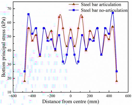
Figure 8.
Schematic diagram of force changes at the bottom of the joint.
As can be seen in Figure 8, the articulated treatment leads to a slight increase in principal stresses at the joint. This is because the articulated connection allows some relative rotation between the plates, and this rotation generates additional stresses at the joint. However, the magnitude of this stress increase is usually acceptable and can be further controlled in practice by sensible design and construction measures.
In addition, the trends of the maximum principal stress at the bottom of the two types of base joint are approximately the same. The average value of the maximum principal stress of the articulated joint is about 48 KPa, and the average value of the maximum principal stress of the non-articulated joint is 46 KPa. The maximum principal stress value of the articulated joint increased by only 4.2% compared to the non-articulated joint, which indicates that the overall stress at the bottom of the joint is relatively smooth under the action of the articulated reinforcement. Articulated treatment restricts the relative displacement of the subgrade plate, effectively reduces the stress fluctuation of the joint area, and thus enhances the stability of the structure.
As can be seen in Figure 9, through the articulation of the steel bar, the compressive stress of the subgrade joint is significantly reduced, and the vertical compressive stress at the bottom of the joint decreases from 83 KPa to 52 KPa, a decrease of about 37%. The maximum value of compressive stress of the articulated joint is about 32% lower than that of the non-articulated joint, a decrease of 33 KPa; the minimum value of compressive stress of the articulated joint is 30 KPa, a decrease of about 49% compared with the minimum value of compressive stress of the non-articulated joint of 59 KPa.
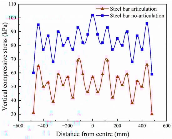
Figure 9.
Schematic diagram of vertical compressive stress change at the bottom of the joint.
The articulated treatment significantly enhances the slabs’ load transfer capacity and improves the structure’s overall stability and durability compared to the traditional rigid connection. As the articulated connection allows relative rotation between the slabs, the deformation difference and constraint are reduced, and the force on the base slabs is more uniform, reducing the risk of joint reflection cracks.
In summary, the articulated treatment of assembled subgrade joints significantly reduces the risk of joint reflection cracks and is worth applying reasonably in actual projects.
3.1.2. Finite Element Analysis of Crack Extension
In this section, based on the theory of fracture mechanics, the expansion analysis of prefabricated cracks in articulated assembled subgrades is carried out by the XFEM module in ABAQUS. In this section, one of the unfavorable loading positions of the slab edge is taken as an example, and Figure 10 shows the simulated changes in prefabricated cracks schematically.
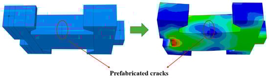
Figure 10.
Schematic diagram of simulated changes in prefabricated cracks.
Compared with the conventional subgrade, the articulated subgrade plate is articulated at both ends by the steel bar, which makes the plate more securely pulled at both ends when subjected to force, effectively controlling the settlement amplitude of the plate, so that it exhibits smaller displacement compared with the conventional subgrade. However, the corresponding tensile stress at the bottom of the slab increases, so the prefabricated cracks expand more.
As shown in Figure 11, for the two types of grass-roots level, I and III, the crack stress intensity factor value is small, for II the crack stress intensity factor is significant, so the crack extension is mainly shear cracks, and the maximum value of KII is 0.53 MPa·m−1/2. Therefore, we must strictly control the articulated grass-roots level plate material performance, ensure the grass-roots level structural strength, reduce the risk of reflective cracking, and ensure the pavement structure’s safety to extend the pavement structure’s service life.
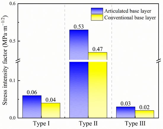
Figure 11.
Schematic diagram of stress intensity factor.
3.2. Analysis of the Effect of Structural Layer Parameters on Joint
3.2.1. Surface Moduli and Thickness Effect
Table 7 shows the change in joint force under different surface layer moduli of the articulated assembled subgrade, and the moduli are selected concerning the current road specification, which is taken as 800–3200 MPa. Figure 12 shows the effect of articulation form on joint forces at 1200 MPa moduli of the surface layer.
Table 7.
Variation in force at joint with different surface moduli.
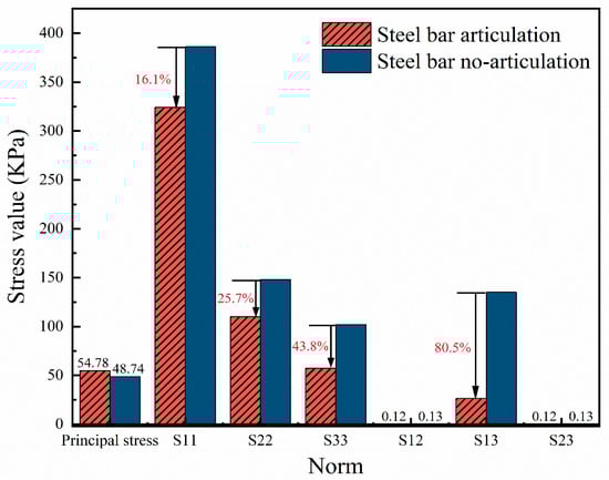
Figure 12.
Schematic diagram of the variation in joint stress value.
As shown in Table 7 and Figure 12, the maximum principal stress of the articulated subgrade joint decreases with the gradual increase in the surface moduli. However, the decrease is only 0.26%, and the changes in other stress values are also minimal. This result indicates that the change in the moduli of the asphalt surface layer does not significantly affect the stress state of the articulated subgrade joint. Secondly, the maximum principal stresses in the joint of articulated sub-subgrades were slightly increased by about 12.4% at 1200 MPa moduli compared to the conventional assembled sub-subgrades. However, this increased stress value did not significantly affect the stress state of the subgrade joint. On the contrary, in the x, y, and z directions, the stress values of the articulated subgrade joint were reduced by 16.1%, 25.7%, and 43.8%, respectively, which indicated that the reinforced articulated structure played an important role in dispersing and relieving the stresses in the joint. In particular, the stress value in the z-direction (i.e., the direction perpendicular to the plane of the joint) was reduced by the most significant amount of 43.8%, which further proves the advantages of the steel-reinforced articulated structure in enhancing the overall stability and durability of the joint. In addition, the reduction in shear force is even higher at 80.5%, and the significant reduction in shear force implies that the articulated subgrade joint has been significantly improved in terms of shear resistance, which helps to reduce the risk of damage to the joint due to overstressing.
In summary, there are significant advantages of reinforced articulated structure in reducing the force on the subgrade joint and improving the stability and durability of the joint. Compared with conventional assembled subgrade, the articulated subgrade joint shows superior performance in the stress state. Therefore, in the actual project, we can consider using a reinforced articulated structure to optimize the design of the grass-roots joint to improve the road structure’s overall performance and service life. At the same time, when selecting the moduli of the asphalt surface layer, we can choose flexibly according to the actual needs without worrying too much about its adverse effect on the stress state of the base joint.
According to Table 8, the principal stress decreased from the initial 54.78 KPa to 49.81 KPa, with a decrease of 9%. This change not only reflects the practical mitigating effect of the increase in the thickness of the surface layer on the stresses of the base joint but also reveals the possibility of optimizing the stress state of the joint by adjusting the thickness of the surface layer. Meanwhile, the decrease in shear stress is more significant, reaching 27%. The significant reduction in the shear stress implies that the stress of the joint in the shear direction is effectively improved, which is important for enhancing the shear capacity of the joint and prolonging its service life. In addition, the stress values in all three directions (x, y, and z) also decreased to different degrees, which further proves the positive effect of the increase in the thickness of the surface layer on the overall improvement of the stress state of the joint.
Table 8.
Variation in force at joint with different surface thicknesses.
3.2.2. Substrate Moduli and Thickness Effect
Table 9 shows the variation in joint stresses at different base moduli for the articulated assembled subgrade. Figure 13 shows the effect of articulated form on joint forces at 25,500 MPa moduli versus 32,500 MPa moduli for the assembled subgrade.
Table 9.
Variation in force at joint with different base moduli.
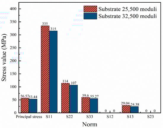
Figure 13.
Schematic diagram of the effect of base moduli on joint stress.
As seen from Table 9 and Figure 13, with the increased moduli of the articulated assembled base slab, the stresses in the joint are all reduced to different degrees. The reduction in joint principal stress is only 3.13 KPa, about 5.5%, and the trend of principal stress decrease is relatively low. x, y, z directions stress values are reduced by 20 KPa, 7 KPa, 4.33 KPa, which are, respectively, 6%, 6%, 7.3%; the reduction in tangential stress is 4.66 KPa, which is about 16%. In summary, as the main load-bearing structure of the assembled subgrade, the increase in the moduli of the base block will improve the overall load-bearing capacity of the subgrade structure, which will alleviate the concentrated stress at the joint location. This is because, with the increase in the moduli of the base block, the subgrade structure can better resist the external loads, thus improving the durability of the pavement.
Table 10 shows the variation in forces at the joint for different assembled subgrade thicknesses. Figure 14 shows the effect of articulated form on joint forces at 200 mm thickness versus 400 mm thickness of the assembled subgrade.
Table 10.
Variation in force at joint with different subgrade thicknesses.
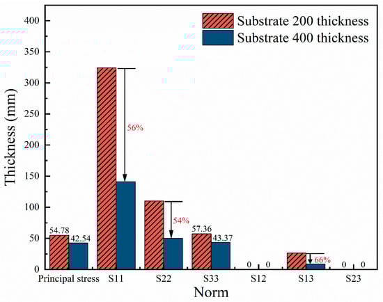
Figure 14.
Schematic diagram of the effect of subgrade thickness on joint stress.
As seen from Table 10 and Figure 14, with the gradual increase in the thickness of the subgrade slab, the stress values of the subgrade joint in all directions show a significant decreasing trend. The value of principal stress decreased significantly from the initial 54.78 KPa to 42.54 KPa, and this decrease reached about 22%, indicating that the increase in subgrade thickness significantly relieved the principal stress. Meanwhile, the stress values in the x-direction decreased by 183 KPa, the y-direction decreased by 59.9 KPa, and the z-direction decreased by 14 KPa. These reductions were about 56%, 54%, and 24%, respectively, further confirming the positive effect of the increase in subgrade thickness on reducing joint stresses. In addition, the shear stress also showed a significant decrease, which was about 66%, and this data supports the above conclusion.
In summary, the increase in the thickness of the subgrade slab can not only effectively reduce the stress influence of the joint in all directions and reduce the occurrence of stress concentration phenomenon but also play a significant positive role in improving the overall bearing capacity of the pavement structure.
3.2.3. Effect of Soil Base Moduli
Table 11 shows the variation in joint stresses for different soil base moduli of articulated assembled subgrade.
Table 11.
Variation in force at joint under different soil base moduli.
As can be seen from Table 11, with the increase in soil base moduli from 30 MPa to 150 MPa, the joint principal stress decreases from 54.78 KPa to 48.44 KPa, a decrease of nearly 11.6%; the shear stress decreases significantly from 26.41 KPa to 11.28 KPa, a decrease of about 57.3%; the values of the stresses in the three directions of x, y, and z decrease significantly, respectively, by about 32%, 30%, and 14%. Secondly, the decrease in shear stress is more significant. It decreases from 26.41 KPa to 11.28 KPa; the decrease ratio is about 57.3%. In addition, the stress value in the x-direction decreased by about 32%, the stress value in the y-direction decreased by about 30%, and the stress value in the z-direction decreased by about 14%. The combined decrease in stress values in these three directions further demonstrates the overall improvement effect of the increase in soil base moduli on the stress state of the joint. In particular, the relatively significant decreases in the stress values in the x and y directions indicate that the stresses on the joint in the horizontal direction have also been effectively relieved.
In summary, the data in Table 11 fully demonstrate the positive effect of the increase in soil base moduli on the stresses in the joint of articulated assembled subgrade. The increase in soil base moduli not only helps to reduce the principal and shear stresses of the joint but also comprehensively improves the stress state of the joint in the three directions. Therefore, in practical engineering, we can optimize the stress state of joint by reasonably adjusting the soil base moduli, improving road structures’ overall performance and service life.
In this section, the effect of the articulation form on the joint forces at soil base moduli of 120 KPa is comparatively analyzed with an example of a soil base moduli of 120 MPa. The results of the analysis are shown in Figure 15.
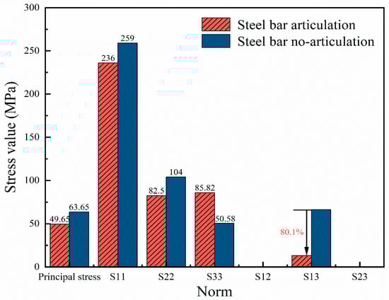
Figure 15.
Schematic diagram of the variation in joint stress values.
As can be seen from Figure 15, under the condition that the soil base modulus is set at 120 MPa, except for the stress value in the z-direction (i.e., the S33 direction), the stress values of the articulated joints in all the other directions show a tendency to be lower than that of the unarticulated joints. In the key index of maximum principal stress, the value of articulated joints is reduced by about 22% compared with that of articulated joints, which is a significant reduction that demonstrates the advantages of articulated structures in dispersing and relieving the stresses.
Regarding the tangential stress , the reduction in the articulated joint is the most prominent, reaching about 80%. This data not only highlights the excellent performance of the reinforced articulated joint in improving the shear capacity of the joint but also provides strong evidence for our understanding of how reinforced articulated joints can enhance the overall bearing capacity of assembled subgrade joints. Therefore, the application of reinforcing steel articulation has a significant and positive impact on improving the load-bearing capacity of the assembled subgrade joint.
3.3. Analysis of the Effect of Joint Material Parameters on Joint
To accurately simulate the mechanical response behavior of joints in assembled base structures, this paper establishes different kinds of linear viscoelastic material models by varying the Poisson’s ratio and modulus of elasticity of asphalt. Figure 16 shows a schematic diagram of the effect of different asphalt materials on the principal stress at the bottom of the joint.
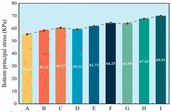
Figure 16.
Schematic diagram of the effect of asphalt material on the bottom of the joint.
As seen from Figure 16, the bottom principal stress of the asphalt A to asphalt I models shows a general increasing trend with the increasing material parameters. Among them, the difference between the principal stresses of Asphalt I and Asphalt A models is 14.57 KPa, with an increase of about 20.8%. This result indicates a significant relationship between Poisson’s ratio and elastic modulus of asphalt and principal stresses, and the smaller the Poisson’s ratio and elastic modulus of asphalt materials are, the lower the bottom principal stresses are subjected to. Under external force, the lower principal stress helps the material adapt to deformation, reduces the risk of stress concentration and local damage, and meets the high requirements of flexibility and ductility of joint materials. Based on the above analysis, the joint material should have the following key performance requirements when screening: firstly, it has good flexibility and strong stress absorption ability to alleviate the stress fluctuation caused by external force; secondly, it has excellent anti-cracking performance, which can effectively delay the occurrence and expansion of cracks. Combining these requirements, the Asphalt A model performs best in this regard. According to the material parameters provided by the asphalt A model, this paper selects the rubber-modified asphalt with the most similar characteristics as the joint material for subsequent research. In addition, rubber-modified asphalt inherently benefits from the excellent thermal adaptability of rubber, which maintains high-temperature stability and low-temperature flexibility. This dual performance advantage ensures stable mechanical properties over various temperatures, minimizing risks such as high-temperature rutting and low-temperature cracking.
3.4. Performance Analysis of Rubber-Modified Asphalt
3.4.1. Characterization of the Three Indicators
In this paper, three major conventional indicators of rubber-modified asphalt with different mesh numbers were tested. Three sets of specimens were prepared, and the results of three tests were averaged. Penetration, softening point, and ductility data graphs are shown below.
As can be seen from Figure 17, Figure 18 and Figure 19, after rubber powder is added to the base asphalt, the penetration appeared to varying degrees of reduction, the softening point enhancement was more significant, and the increase in ductility had slight ups and downs. By comparing the three different mesh rubber-modified asphalts, the following can be found: 20 mesh rubber-modified asphalt penetration is significant, with the softening point of less promotion, and the most increase in ductility. This indicates that 20 mesh rubber-modified asphalt is softer and more fluid at high temperatures, which may lead to joint material flow and deformation, affecting the sealing effect. However, its low-temperature toughness and crack-resistant performance are good. The 60 mesh rubber-modified penetration is moderate, the softening point is the highest, and the ductility compared to the ordinary matrix asphalt has also improved. This indicates that 60 mesh rubber-modified asphalt performance has been significantly improved in all aspects. The 100 mesh modified asphalt needle penetration is small, the softening point increases, and the effect of the increase in ductility is not apparent. This indicates that 100 mesh rubber-modified asphalt is harder, which may lead to brittle cracking at low temperatures, and the joint material is prone to failure.
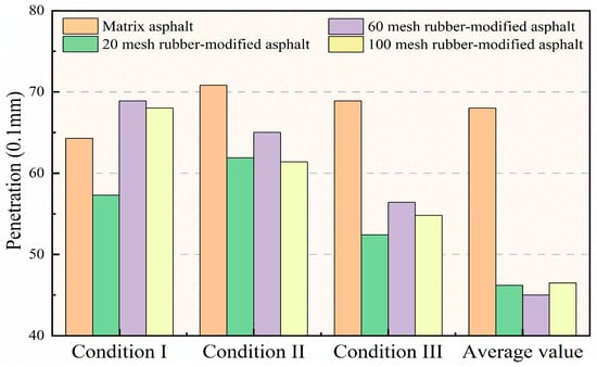
Figure 17.
Penetration data graph.
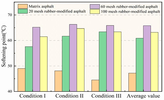
Figure 18.
Softening point data graph.
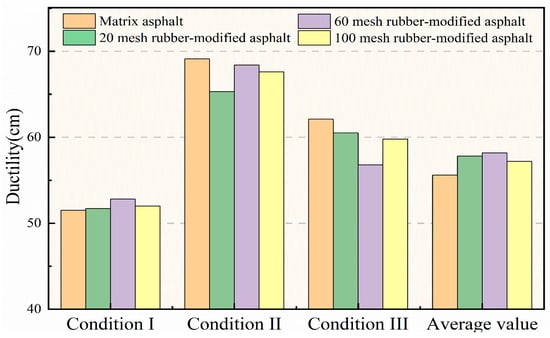
Figure 19.
Ductility data graph.
3.4.2. Characterization of the Viscosity
The temperature range of Brinell’s rotational viscosity test is 135–175 °C with an interval of 20 °C, and the results of the rotational viscosity test of the rubber-modified asphalt are shown in Table 12 below. The viscosity–temperature curve is shown in Figure 20.
Table 12.
Brinell’s rotational viscosity test chart.
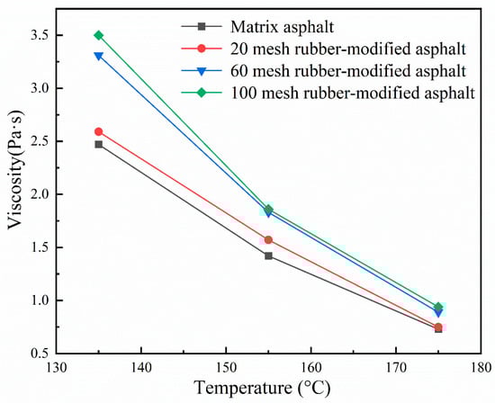
Figure 20.
Rubber-modified asphalt viscosity-temperature curve.
As shown in Table 12 and Figure 20, compared with the base asphalt, with the addition of rubber powder, modified asphalt viscosity increases, indicating that the rubber particles and asphalt combine to form a more uniform structure, improving the cohesion of asphalt, thus increasing the viscosity. The 20 mesh rubber-modified asphalt viscosity increase compared to the matrix asphalt is not apparent, 60 mesh rubber-modified asphalt viscosity growth is the fastest, and 100 mesh rubber-modified asphalt viscosity is slightly higher than the 60 mesh rubber-modified asphalt. At different temperatures, the magnitude improves by only 5.4%, 1.6%, and 5.3%, which is not much growth.
In summary, 60 mesh rubber-modified asphalt has the best overall performance, with strong adhesion to cement concrete slab joint walls, good resilience, adaptability to the characteristics of concrete panel shrinkage, and a high tensile ratio. Its high and low-temperature performance is also superior.
3.4.3. Rubber-Modified Asphalt Construction Applications
In the actual engineering application, 60 mesh rubber-modified asphalt was selected as the joint grouting material, and the parameter list of the structural layer at the construction site is shown in Table 13.
Table 13.
Construction site structural layer parameters.
In the process of grouting construction, it is necessary to strictly control the matching ratio and fluidity of the material and grout according to the design requirements and sequence to ensure the quality of the grouting and the stability of the road structure and to complete the use within the specified time. The grouting construction application process is shown in Figure 21.
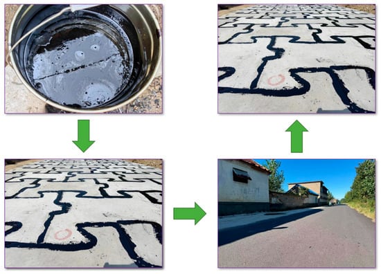
Figure 21.
Grout construction application diagram.
The research results of this project have been successfully applied in the Qufu City Rural Habitat Environment (Four Good Rural Roads Renovation) Enhancement Project. The application of this technology not only improves the construction efficiency and service life of the road but also significantly reduces the impact of the construction on the environment, which has extensive promotional potential and practical application value.
3.4.4. Limitations Statement
This study employed a simplified model structure primarily based on numerical simulation analysis under software conditions. Consequently, external factors (such as dynamic loads and temperature fluctuations) and the combined effects of multiple factors were not considered. Particularly during the simulation process, the mechanical behavior of road joints did not fully reflect the complex environmental and operational variations that may occur in actual road conditions. Therefore, the model may not fully capture the mechanical response under real-world conditions to a certain extent.
Our team envisions that future research should focus on integrating long-term field monitoring with experimental data under actual engineering conditions to further analyze the mechanical behavior of articulated prefabricated base asphalt pavement joints. Field data collection will enable more precise evaluation of how factors like fatigue accumulation, temperature variations, and load effects influence joint material performance over extended service life, providing a more comprehensive theoretical basis for pavement design and maintenance.
4. Conclusions
In this paper, we start from the structure of the assembled subgrade slab and use ABAQUS finite element software to establish articulated assembled subgrade asphalt pavement, revealing the influence of steel articulation on the force of assembled road joint. We then discussed the structural layer and material parameters on the mechanical response of the change rule of the joint. Finally, we selected the optimal rubber-modified asphalt as the joint material and applied it to the field construction. The main conclusions are as follows:
- (1)
- Reinforcing steel articulation causes the maximum principal stress at the joint to increase by only 4.2%, and the reduction in compressive stress comes at the expense of increased tensile stress, which is in line with the specification requirements. Reinforcing steel articulation causes the vertical compressive stress at the bottom of the joint to decrease by about 37%, and the maximum value of compressive stress in articulation joint decreases by about 32% compared with that of the no-articulated joint, while the minimum value decreases by about 49%. Reinforcing steel articulation effectively reduces the displacement of the plate, enhances the cooperative deformation capacity of the subgrade plate, and reduces the risk of reflective cracking in the joint.
- (2)
- In the mechanical response analysis of joint, the changes in different structural layer parameters influence the joint force differently. They mainly manifested as follows: the change in moduli of the surface layer and subgrade layer has less influence on the joint force; when the modulus is in the maximum state, the principal stress at the joint only decreases by 0.26% and 5.5%; the change in modulus of the soil base has a more significant influence on the joint force, and the maximum value can make the principal stress at the joint decrease by about 11.6% compared to the minimum value; the thickness of the surface layer and subgrade layer have a significant influence on the joint force, and with the increase in thickness, the principal stress at the joint can decrease by about 9% and 22%, respectively. The thickness of the surface layer and subgrade layer has a significant effect on the joint force, and with the increase in thickness, the principal stress at the joint can be decreased by about 9% and 22%, respectively.
- (3)
- In the analysis of joint material properties, there is a significant relationship between Poisson’s ratio and modulus of elasticity of asphalt and principal stresses, and the smaller the material parameters, the lower the principal stresses experienced at the bottom of the joint. The maximum value of the joint material parameter can increase the principal stress at the joint by 20.8% compared to the minimum value. Therefore, choosing rubber-modified asphalt with a low Poisson’s ratio and modulus of elasticity, good flexibility, stress absorption performance, and crack resistance as joint material is necessary.
- (4)
- Based on the demand for mechanical properties and stability of joint materials, this paper selects 60 mesh rubber-modified asphalt as the joint material. 60 mesh rubber-modified asphalt has moderate needle penetration, the highest softening point, and improved ductility compared to ordinary matrix asphalt. 100 mesh rubber-modified asphalt is better than 60 mesh rubber-modified asphalt in terms of viscosity, but the improvement at 135 °C, 155 °C, and 175 °C is only 5.4%, 1.6%, and 5.3%. Therefore, 60 mesh rubber-modified asphalt has the best overall performance, and the practical application effect is also good.
Author Contributions
Y.L.: Conceptualization, Data curation, Methodology, Writing—original draft, Writing—review and editing; X.J. (Xuelei Jiang): Data curation, Methodology, Writing—review and editing; J.Y.: Data curation, Methodology, Writing—review and editing; W.B.: Writing—original draft, Data curation; W.Z.: Methodology, Project administration, Funding acquisition, Data curation, Writing—original draft; K.H.: Funding acquisition, Data curation; L.C.: Writing—original draft, Data curation; X.J. (Xiaoping Ji): Funding acquisition, Data curation. All authors have read and agreed to the published version of the manuscript.
Funding
This research was funded by Shandong Provincial Natural Science Foundation (ZR2025MS808); Technology Development Projects of Haiwei Engineering Construction Co., Ltd., Of Fhec Of CCCC, China, grant number 2024-Keji-272, 2023-Keji-073, 2023-Keji-032; Technology Development Projects of Shandong Gaoyang Construction Co., Ltd., China, grant number 2024-Keji-1022.
Institutional Review Board Statement
Not applicable.
Informed Consent Statement
Not applicable.
Data Availability Statement
All data in this paper are retained by the first author. Date will be made available on request.
Conflicts of Interest
Author Xuelei Jiang was employed by the company Haiwei Engineering Construction Co., Ltd. of FHEC of CCCC. Author Wenpeng Bian was employed by the company Shandong Gaoyang Construction Co., Ltd. The remaining authors declare that the research was conducted in the absence of any commercial or financial relationships that could be construed as a potential conflict of interest.
References
- Liu, H.; Qin, X.; Yang, Z.; Zhang, H.; Lv, S. Assessing bio-oil cutback asphalt for prime coat on semi-rigid base asphalt pavement: Lab experiment & indoor test section application. Constr. Build. Mater. 2024, 422, 135814. [Google Scholar] [CrossRef]
- Yang, Z.; Wang, L.; Cao, D.; Miao, Y.; Yang, H. Structural optimization design of semi-rigid base asphalt pavement using modulus matching criterion and multi-indicator range analysis. J. Traffic Transp. Eng. 2024, 11, 131–159. [Google Scholar] [CrossRef]
- Nie, D.; Wang, S.; Sun, P.; Huang, C. Study on anti-crack effect of semi-rigid base pavement with stress absorbing layer. J. Eng. Appl. Sci. 2023, 70, 45. [Google Scholar] [CrossRef]
- Chen, J.; Li, H.; Zhao, Z.; Hou, X.; Luo, J.; Xie, C.; Liu, H.; Ren, T.; Huang, X. Investigation of transverse crack spacing in an asphalt pavement with a semi-rigid base. Sci. Rep. 2022, 12, 18079. [Google Scholar] [CrossRef]
- Yu, S.; Liu, Y.; Wang, D.; Bahaj, A.S.; Wu, Y.; Liu, J. Review of thermal and environmental performance of prefabricated buildings: Implications to emission reductions in China. Renew. Sustain. Energy Rev. 2021, 137, 110472. [Google Scholar] [CrossRef]
- Yu, L.; Xie, J.; Li, R.; Hu, J.; Pei, J. Study on the performance of emulsified asphalt recycled subgrade based on the evaluation of semi-rigid milling material. Constr. Build. Mater. 2022, 324, 126614. [Google Scholar] [CrossRef]
- Cheng, Z.; Zhang, T.; Zhou, X.; Li, Z.; Jia, Y.; Ren, K.; Xu, T.; Li, C.; Hong, J. Life cycle environmental and cost assessment of prefabricated components manufacture. J. Clean. Prod. 2023, 415, 137888. [Google Scholar] [CrossRef]
- Wu, D.; Yang, J.; Zang, X.; Shi, S.; Xing, J.; Liu, Y.; Yang, J.; Cui, L.; Su, T.; Cao, X.; et al. Mechanical response study of articulated assembled base course asphalt pavement based on numerical simulation. Mater. Struct. 2024, 57, 246. [Google Scholar] [CrossRef]
- Sun, R.; Fang, Q.; Zhang, H.; Jiang, Y.; Ma, K.; Wei, M.; Wu, S. Experimental and numerical investigation of the assembled monolithic spherical-shaped reinforced concrete ribbed folded plate structure. Front. Struct. Civ. Eng. 2025, 19, 300–317. [Google Scholar] [CrossRef]
- Peng, J.; Feng, Y.; Zhang, Q.; Liu, X. Multi-objective integrated optimization study of prefabricated building projects introducing sustainable levels. Sci. Rep. 2023, 13, 2821. [Google Scholar] [CrossRef]
- Tan, Q.; Zhu, H.; Yang, S.; Yang, X.; Ou, L. Precast Assembled Road Paving Technology: Progress and Prospects. Materials 2024, 17, 2245. [Google Scholar] [CrossRef]
- Lai, H.; Xu, A.; Zhai, J.; Zong, Y.; Deng, W.; Guo, H.; Wang, Z. A Systematic Review of Montmorillonite-Asphalt Composite Materials: Green Clay Mineral-Reinforced Asphalt for Sustainable Pavement Solutions. Appl. Clay Sci. 2025, 278, 108007. [Google Scholar] [CrossRef]
- Tavares, V.; Gregory, J.; Kirchain, R.; Freire, F. What is the Potential for Prefabricated Buildings to Decrease Costs and Contribute to Meeting EU Environmental Targets? Build. Environ. 2021, 206, 108382. [Google Scholar] [CrossRef]
- Liu, D.; Fu, Q.; Wang, J.; Wang, M.; Li, W.; Liu, M. Study on recyclable precast-slab-fabricated road based on arching effect theory. Eng. Res. Express 2022, 4, 045019. [Google Scholar] [CrossRef]
- Han, Y.; Fu, J.; Zhang, Q.; Zhang, H.; Yang, F. Monitoring and evaluation of energy consumption in the whole process of asphalt pavement construction. IOP Conf. Ser. Earth Environ. Sci. 2021, 804, 042058. [Google Scholar] [CrossRef]
- Zhu, H.; Wei, G.; Xu, H.; Yu, X.; Ma, D. The influence of interlayer bonding conditions on the propagation laws of reflective cracks in semi-rigid base pavement based on the DEM and GPR. Constr. Build. Mater. 2024, 442, 137547. [Google Scholar] [CrossRef]
- Si, C.; Cao, H.; Fan, T.; Jia, Y.; Wang, X.; Li, S.; Xu, Z.; Gu, J. Study on crack propagation behavior of bridge deck asphalt pavement. Constr. Build. Mater. 2024, 425, 136136. [Google Scholar] [CrossRef]
- Park, H.-W.; Lee, J.-H.; Jeong, J.-H. Finite element analysis of continuously reinforced bonded concrete overlay pavements using the concrete damaged plasticity model. Sustainability 2023, 15, 4809. [Google Scholar] [CrossRef]
- Xie, P.; Wang, H. Finite element analysis of thermal-induced reflective cracking in composite pavement with mitigation strategies. Eng. Fract. Mech. 2022, 266, 108396. [Google Scholar] [CrossRef]
- Xiao, M.M.; Fan, L. Analysis of the extension behavior of reflective cracks in asphalt pavements based on dry shrinkage property. SN Appl. Sci. 2022, 4, 88. [Google Scholar] [CrossRef]
- Jiao, L.; Harvey, J.T.; Wu, R.; Deng, H. Study on thermal reflective cracking of asphalt concrete overlays on concrete pavements under moderate temperature variations using finite element model. Transp. Res. Rec. 2024, 2678, 162–176. [Google Scholar] [CrossRef]
- Rith, M.; Lee, S.W. Evaluation of asphalt overlay pretreatments against reflective crack using association rule mining. J. Transp. Eng. Part B Pavements 2021, 147, 3. [Google Scholar] [CrossRef]
- Sun, H.-g. Development of an indoor test method for evaluating the anti-reflection crack performance of asphalt overlay. Case Stud. Constr. Mater. 2023, 19, e02241. [Google Scholar] [CrossRef]
- Ma, H.; Zhang, Z. Paving an engineered cementitious composite (ECC) overlay on concrete airfield pavement for reflective cracking resistance. Constr. Build. Mater. 2020, 252, 119048. [Google Scholar] [CrossRef]
- Luan, Y.; Zhang, W.; Ma, T.; Cao, J.; Shi, X.; Tong, Z. Effect of existing pavement condition and overlaying strategy on the reflective cracking resistance of asphalt pavement. Constr. Build. Mater. 2023, 401, 132620. [Google Scholar] [CrossRef]
- Gao, J.; Qiu, Z.; Xiong, C. Mechanical Response and Anti-Reflective Crack Design in New Asphalt Overlays on Existing Asphalt Overlaying Composite Portland Cement Pavement. Buildings 2024, 14, 2702. [Google Scholar] [CrossRef]
- Fang, N.; Wang, X.; Chang, H.; Yu, K. Design Approach for Composite Pavement Structure Incorporating Reflective Crack Considerations. Appl. Sci. 2025, 15, 1691. [Google Scholar] [CrossRef]
- Dong, Z.; Guo, Z.; Zhang, H.; Li, J. Optimal design of prefabricated base joint for asphalt pavement based on finite element method and field deflection test. Constr. Build. Mater. 2022, 345, 128301. [Google Scholar] [CrossRef]
- Zhu, Z.; Al-Qadi, I.L. Development of a full-scale approach to predict overlay reflective crack. Int. J. Pavement Eng. 2024, 25, 2310095. [Google Scholar] [CrossRef]
- Liu, H.; Lu, H.; Zhu, X.; Yi, Z.; Yu, X.; Jin, D.; Peng, X.; Lv, S. Fatigue Life of Pre-Cut Seam Asphalt Mixture Composite Beams: A Combined Study of Fatigue Damage Evolution and Reflective Cracking Extension. Buildings 2025, 15, 50. [Google Scholar] [CrossRef]
- Wang, J.; Zhang, C.; Zhang, W. Seismic Performance Analysis of the Internal Joint in the New Demountable Fabricated Concrete Frame with Prestressed Mortise–Tenon Connections. Sustainability 2024, 16, 7898. [Google Scholar] [CrossRef]
- Huang, Z.; Bai, H.-w.; Ma, S.-k.; Zhang, J.-w.; Chen, Y.-m.; Li, H.-z. Large-scale testing of the mortise and tenon joint performance of the tunnel lining of prefabricated frame tunnels. Tunn. Undergr. Space Technol. 2023, 131, 104828. [Google Scholar] [CrossRef]
- Zhang, C.; Zhang, W.; Li, W.; Wang, J.; Du, X. Experimental study on axial compression performance of unbonded prestressed mortise-tenon precast concrete mid joint. J. Build. Eng. 2024, 86, 108819. [Google Scholar] [CrossRef]
- Deng, J.; Zhao, W.; Wang, J.; Li, J.; Wu, B.; Li, X.; Liu, X.; Chen, L.; Liu, T.; Zhu, S.; et al. A novel design of an I-shape self-locked thin-walled system with mortise and tenon joints. Thin Walled Struct. 2024, 201, 111966. [Google Scholar] [CrossRef]
- Zhu, Y.; Meng, D.; Zhang, Y.; Hussein, H.H.; He, S. Long-term performance of a continuous box-girder bridge constructed using precast segments with wet ultra-high-performance concrete (UHPC) joints. Case Stud. Constr. Mater. 2022, 17, e01285. [Google Scholar] [CrossRef]
- Abdel-Jaber, H.; Glisic, B. Monitoring of long-term prestress losses in prestressed concrete structures using fiber optic sensors. Struct. Health Monit. 2019, 18, 254–269. [Google Scholar] [CrossRef]
- Hong, C.; Rao, W.; Qiu, T.; Chen, X.; Dai, J.; Wu, C.; Li, M.; Chen, W. Monitoring and assessment of mechanical response of large-scale prefabricated structures in underground subway stations during construction process. Measurement 2024, 235, 115015. [Google Scholar] [CrossRef]
- Cheng, Y.; Wang, H.; Zhang, Y.; Li, L.; Bai, Y.; Sun, X.; Xu, Z.; Liang, J. Evaluation of the properties of cement mortar used in prefabricated road base as caulking material. J. Test. Eval. 2022, 50, 1859–1870. [Google Scholar] [CrossRef]
- Zhang, W.; Yu, X.; Wu, D.; Song, B.; Cao, X.; Xing, Z.; Zhang, Y.; Yan, X.; Ji, X.; Hu, K.; et al. Evaluation method of modification effect of direct-to-plant SBS modifier on asphalt. Constr. Build. Mater. 2024, 419, 135569. [Google Scholar] [CrossRef]
- Yang, R.; Zhan, C.; Fan, Y.; Xia, Y.; Wu, Y.; Yang, J. Characterizing the cracking features of seamless asphalt plug joint (SAPJ) under cooling process using ABAQUS and FE-SAFE. Constr. Build. Mater. 2025, 470, 140569. [Google Scholar] [CrossRef]
- Jiang, B.; Xu, L.; Cao, Z.; Yang, Y.; Sun, Z.; Xiao, F. Interlayer distress characteristics and evaluations of semi-rigid base asphalt pavements: A review. Constr. Build. Mater. 2024, 431, 136441. [Google Scholar] [CrossRef]
- Liu, Y.; Qian, Z.-D.; Xie, Y.-X.; Xu, S.-Q. Investigation on materials for prefabricated bridge deck pavement and construction technology: Application to a case study of concrete box-girder bridge. Case Stud. Constr. Mater. 2024, 20, e03185. [Google Scholar] [CrossRef]
- Kim, K.-N.; Kim, Y.-M.; Le, T.H.M. Development of Plug Joint with Polymer-Modified Rubber Asphalt as Filling Material. Polymers 2023, 15, 4256. [Google Scholar] [CrossRef] [PubMed]
- Kamau, J.; Podolsky, J.; Williams, R.C. Performance evaluation of a HMA pavement longitudinal joint containing a void reducing asphalt membrane (VRAM). Front. Mater. 2023, 10, 1154873. [Google Scholar] [CrossRef]
- GB/T 19208-2008; Ground Vulcanized Rubber. Standards Press of China: Beijing, China, 2008.
- GB/T 4498.1-2013; Rubber—Determination of Ash—Part 1: Muffle Furnace Method. Standards Press of China: Beijing, China, 2013.
Disclaimer/Publisher’s Note: The statements, opinions and data contained in all publications are solely those of the individual author(s) and contributor(s) and not of MDPI and/or the editor(s). MDPI and/or the editor(s) disclaim responsibility for any injury to people or property resulting from any ideas, methods, instructions or products referred to in the content. |
© 2025 by the authors. Licensee MDPI, Basel, Switzerland. This article is an open access article distributed under the terms and conditions of the Creative Commons Attribution (CC BY) license (https://creativecommons.org/licenses/by/4.0/).