Abstract
A Multimode Propulsion System (MPS) is an innovative spacecraft thruster concept that integrates two or more propulsion modes sharing the same type of propellant. A spacecraft equipped with an MPS can potentially combine the advantages of continuous-thrust electric propulsion and medium-to-high-thrust chemical propulsion within a single vehicle, while reducing the overall mass compared to traditional configurations where each propulsion system uses a different propellant. This feature makes the MPS concept particularly attractive for small spacecraft, such as the well-known CubeSats, which have now reached a high level of technological maturity and are employed not only in geocentric environments but also in interplanetary missions as support elements for conventional deep-space vehicles. Within the MPS framework, a Monopropellant-Electrospray Multimode Propulsion System (MEMPS) represents a specific type of micropropulsion technology that enables a single miniaturized propulsion unit to operate in either catalytic-chemical or electrospray-electric mode. This paper investigates the flight performance of a MEMPS-equipped CubeSat in a classical circle-to-circle orbit-raising (or lowering) maneuver within a two-dimensional mission scenario. Specifically, the study derives the optimal guidance law that allows the CubeSat to follow a transfer trajectory optimized either for minimum flight time or minimum propellant consumption, starting from a parking orbit of assigned radius and targeting a final circular orbit. Numerical simulations indicate that a heliocentric orbit raising, increasing the initial solar distance by , can be achieved with a flight time of approximately 11 months and a propellant consumption slightly below 6 kg. The proposed method is applied to a heliocentric case study, although the procedure can be readily extended to geocentric transfer missions, which represent a more common application scenario for current CubeSat-based scientific missions.
1. Introduction
Multimode propulsion systems (MPS) are emerging technologies in the field of spacecraft propulsion that integrate two or more propulsive modes using the same type of propellant. The main advantage lies in the ability to share a single propellant—encompassing flow distribution and tank infrastructure—across multiple propulsion modes, such as a pure-chemical high-thrust mode and a pure-electric high-specific impulse mode.
A recent review by Rovey et al. [1] presents the latest advancements in the MPS concept and addresses an intriguing issue regarding nomenclature. In some cases, the terminology used in the scientific literature to describe this type of spacecraft thruster becomes confusing or even contradictory. For instance, the paper by Arya et al. [2] investigates the optimal transfer performance of a realistic multimode propulsion system, considering a suitable sequence of low-thrust arcs and gravity assist maneuvers. However, the term “multimode” in ref. [2] refers to the finite set of discrete operating levels derived from the thrust table of the solar electric propulsion system analyzed in that study. In this context, “multimode” corresponds to the more conventional concept of “thrust level” which was also employed by the first author in ref. [3] approximately fifteen years ago to evaluate the transfer performance of NASA’s solar electric propulsion systems [4,5].
The introduction of ref. [1] also provides a valuable overview of the various types of thrusters that can be integrated within the broader MPS framework, as illustrated in the first figure of that reference. That image has been redrawn in Figure 1 to offer the reader a snapshot of the possible types of multimode thrusters and their relative performance in terms of specific impulse values.
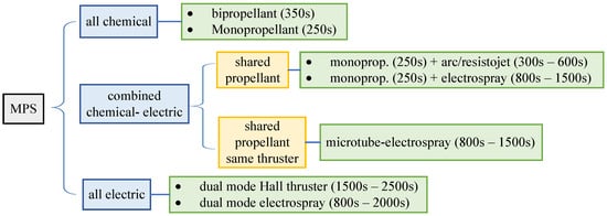
Figure 1.
Types of multimode propulsion systems and their corresponding specific impulse values (indicated in brackets). Conceptual diagram adapted from ref. [1], with permission.
From a conceptual standpoint, traditional hybrid propulsion systems rely on two distinct space engines installed aboard the same spacecraft, each operating with a different type of propellant—for example, a classical chemical thruster combined with an electric thruster [6,7], or an electric thruster paired with a photonic solar sail [8,9]. In contrast, an MPS enables the exploitation of a single, suitable space propellant through two fundamentally different propulsive mechanisms. This approach allows, for instance, the integration within the same spacecraft of the benefits offered by a solar electric thruster—which typically provides continuous, steerable, and very low propulsive acceleration with high specific impulse—and those of a chemical thruster, capable of delivering medium-to-high acceleration magnitudes with relatively low specific impulse.
Notably, the latter characteristic of chemical thrusters permits the use of the useful approximation of an “impulsive maneuver” during the preliminary phase of spacecraft trajectory design. More importantly, the potential reduction in tankage fraction—an inherent feature of MPS—enables the combination of high-thrust and low-thrust propulsion systems with a significant saving in the total mass of the installed space engine.
Indeed, the theoretical ability to freely select the propulsion mode during orbital flight offers a degree of flexibility in designing the potential orbital transfer trajectory of a spacecraft equipped with an MPS. However, this flexibility introduces complexity in the selection of the guidance law, which—during the preliminary phase of trajectory design—is typically determined through a procedure that optimizes a given performance index, such as flight time, required propellant mass, or a suitable combination of both [10].
In this context, the recent and noteworthy work by Cline et al. [11] applies the classical optimization method based on the calculus of variations to investigate the optimal transfer performance of a vehicle propelled by an MPS. Specifically, ref. [11] employs the hyperbolic tangent smoothing technique introduced by Taheri and Junkins [12] to enhance the convergence domain in solving the boundary value problem associated with the optimization process, in the presence of a classical switching function that models the on/off behavior of the MPS. More importantly, that study explores the effectiveness of a suitable penalty function in evaluating the optimal minimum-time transfer trajectory of a spacecraft equipped with a dual-mode propulsion system, under a constraint on the minimum spacecraft mass—that is, a constraint on the maximum allowable propellant expenditure.
Deep-space CubeSat missions are gaining momentum in the space sector due to their lower cost, launch flexibility, and, in particular, the advancements in the miniaturization of critical instrumentation. However, implementing dedicated propulsion systems on such small satellites remains a significant challenge. The integration of propulsion systems into CubeSats faces numerous constraints stemming from safety requirements, launch conditions, and platform limitations. These constraints are especially stringent for CubeSats launched as secondary payloads, where minimizing the risk to the primary mission is essential. As a result, only a limited number of propulsion technologies have been successfully demonstrated on CubeSat platforms. Notable examples include cold gas thrusters, electrospray thrusters, vacuum arc thrusters, and propellantless systems such as solar sails, all of which offer inherently safer and lower-risk propulsion solutions compatible with CubeSat constraints [13]. A recent review [14] provided a comprehensive overview of the propulsion technologies currently employed in CubeSat missions, highlighting the range of systems that have been demonstrated in orbit and analyzing their performance, capabilities, and limitations within the constraints of the CubeSat platform. The first interplanetary nanospacecraft mission (NASA JPL Mars Cube One—MarCO) [15] was launched in May 2018 as part of the InSight mission. Two 6U CubeSats were launched alongside NASA’s InSight Mars lander. These CubeSats hosted eight cold gas thrusters propelled by R-236FA with a capability of . Following this landmark mission, numerous studies have explored two main architectural approaches: one involving a mother–daughter configuration, in which CubeSats are transported aboard a larger spacecraft to a target destination—such as lunar orbit or a near-Earth object—and deployed upon arrival to carry out their objectives; the other involving fully independent CubeSat missions capable of reaching and operating at their target autonomously. The Lunar Polar Hydrogen Mapper (LunaH-Map) and the Lunar IceCube missions are two 6U CubeSats launched as secondary payloads aboard the maiden flight of the Space Launch System (SLS), Artemis 1, into cis-lunar space in 2022. Both CubeSats are equipped with their own propulsion systems, that is, the iodine-fueled BIT-3 ion thruster developed by Busek [16]. BIT-3 occupies a volume of 1.6U. Iodine was selected as the baseline propellant due to its high storage density in solid form and low vapor pressure compared to xenon, which is more commonly used in electric propulsion. These properties reduce system volume and eliminate the need for a high-pressure tank—advantages that are particularly well suited for CubeSat applications. In this context, MPS offers a notable alternative solution for CubeSat allowing the flexibility to adopt chemical impulsive maneuvers in combination with the continuous electric thruster mode.
In the case of MPS-based CubeSats, and considering the models and results presented in recent literature [1,17] on this propulsion concept, this paper investigates the performance of an innovative Monopropellant–Electrospray Multimode Propulsion System (MEMPS) [18,19] for circle-to-circle orbit raising (or lowering) within a simplified two-dimensional mission scenario. The specific MEMPS examined in this study is a type of micropropulsion technology that combines a chemical monopropellant decomposition mode with an electrospray electric mode [20,21], using a single miniaturized thruster [22] designed to operate with a novel, custom green ionic liquid known as FAM-110A [23].
A schematic representation of a MEMPS with four thruster units operating in either full chemical mode (left side of the image) or full electric mode (right side of the image) is shown in Figure 2. In particular, when a MEMPS includes multiple thruster units, each unit can be operated in either chemical or electric mode. Typically, once the propulsion mode (chemical or electric) of the MPS is selected, each individual thruster unit can be activated or deactivated, thereby providing a certain degree of flexibility in selecting the total thrust delivered by the propulsion system. For instance, referring to Figure 2, the presence of four thruster units enables eight distinct thrust levels—four corresponding to the chemical mode and four to the electric mode.
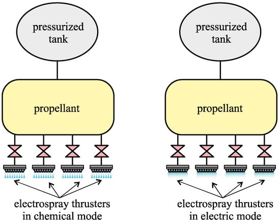
Figure 2.
Schematic representation of a MEMPS with four thruster units operating in two distinct modes: full chemical (left side of the image) and full electric (right side). Image adapted from refs. [1,20].
Therefore, MEMPS appears to be a promising option within the broader context of MPS technologies [24,25]. In fact, the performance of a MEMPS-propelled CubeSat has recently been investigated in a preliminary mission design that includes both a servicing scenario in low-Earth orbit [26] and the transfer trajectory of a scientific small satellite in a lunar mission context. Notably, numerical simulations demonstrated that a MEMPS-equipped spacecraft is capable of completing the four design reference missions considered in that study—including a transfer to low lunar orbit—with significant savings in propellant mass (or flight time) compared to both chemical and conventional electric propulsion systems. On the other hand, the required propellant mass can be further reduced by employing complex transfer trajectories that incorporate, for example, a sequence of lunar flyby maneuvers [27] or the use of dynamical manifolds [28].
The aim of this paper is to extend the analysis of the potential of the MEMPS concept when integrated into a relatively standard small spacecraft, such as a CubeSat, within a typical mission scenario—namely, the transfer between two circular, Keplerian, and coplanar orbits. To this end, the paper derives a simplified thrust model of the MEMPS suitable for use in the preliminary phase of optimal trajectory design, as discussed in the first part of Section 2. The propulsion characteristics defined in the thrust vector model are then employed in Section 2.2 to develop a simplified mass distribution model for the interplanetary CubeSat.
In particular, the mass breakdown model incorporates results from a recent study [17] to characterize the inertial properties (including the onboard propellant mass) of a potential CubeSat designed for scientific missions beyond typical low-Earth orbit. In this regard, some design features of the small spacecraft are also inspired by the deep-space CubeSat M-ARGO (Miniaturised Asteroid Remote Geophysical Observer), proposed by the European Space Agency [29,30], which is expected to be the first CubeSat to perform an interplanetary transfer using its own propulsion system. Specifically, the M-ARGO mission scenario involves a rendezvous with a small, rapidly rotating near-Earth asteroid, starting from a collinear Sun–Earth Lagrange point [31].
The mathematical models developed in Section 2 are subsequently employed in Section 3 to describe the dynamics of a MEMPS-powered CubeSat during heliocentric flight. In this context, a purely two-dimensional dynamical model is adopted, although the thrust model can readily be extended to more general three-dimensional mission scenarios. Specifically, the spacecraft’s motion is modeled by considering only the gravitational attraction of the Sun and the propulsive acceleration generated by the MEMPS, while all orbital perturbations are neglected—an assumption commonly made in preliminary analyses such as the one presented in this paper.
Section 4 introduces the optimal guidance law that enables the MEMPS-propelled CubeSat to follow an optimized heliocentric transfer trajectory, minimizing either the flight time or the propellant mass required to reach the target circular orbit from a given parking orbit. To this end, an indirect optimization method—mathematically consistent with the approach proposed in ref. [11]—is employed to determine the optimal transfer trajectory. However, the strategy adopted in this paper for handling rapid transfers and minimum-propellant transfers differs from those found in the recent literature, as the procedure illustrated in Section 4 draws inspiration from methods previously used by the first author for solar-electric propulsion spacecraft in interplanetary missions involving rendezvous with terrestrial planets [10,32].
In particular, the mathematical model presented in Section 4 assumes that the MEMPS operates exclusively in electric mode during the optimal transfer, while the chemical mode is reserved for trajectory correction maneuvers, which are not explicitly modeled in the simplified framework adopted in this study. Accordingly, the optimization procedure evaluates the relationship between the optimal flight time, the radius of the target circular orbit, the propellant mass consumed in electric mode, and the residual propellant mass available for potential use in chemical mode.
The optimization procedure described in Section 4 has been implemented through a series of numerical routines to investigate the optimal performance of the CubeSat within the selected mission scenario. The results of this numerical analysis are summarized in Section 5, which also presents a parametric study of the optimal orbit raising (or lowering) as a function of the target orbit characteristics. Finally, Section 6 provides the conclusions of the paper and outlines potential extensions of this work.
2. CubeSat Preliminary Characterization
The first part of this section presents the mathematical model used to describe the thrust vector of the MEMPS, while the second part introduces a simplified framework for the preliminary estimation of the mass distribution of an interplanetary CubeSat equipped with such an advanced propulsion system, incorporating results from a recent study [29].
2.1. MEMPS Thruster Description
The multimode propulsion system selected for this study is an innovative single microthruster composed of approximately 1000 microtubes, depending on the required thrust magnitude. In this concept [33], the channels can operate either as catalytic decomposition chemical microtubes—when a high mass flow is initiated—or as electrospray emitters at very low mass flow, when a potential difference is applied between the channels and a facing anode.
A critical aspect in the application of MPS technology is the selection of a suitable propellant capable of supporting multimode operation. The MEMPS has been designed to operate with the novel multimode propellant FAM-110A, a binary mixture of hydroxylammonium nitrate (HAN) and the ionic liquid (IL) fuel [Emim][EtSO4] [23], in a weight ratio of 59:41 HAN–[Emim][EtSO4]. This formulation has been shown to yield a lower combustion temperature (approximately ) while maintaining chemical performance comparable to hydrazine and ASCENT.
In pure monopropellant chemical mode, FAM-110A is predicted to deliver a specific impulse of when used with a nozzle, and approximately without one. For the MEMPS configuration considered in this study, the maximum specific impulse is limited to due to the absence of a nozzle in electrospray operation.
To provide a visual reference of the MEMPS, Figure 3 shows the quarter-scale prototype manufactured by Froberg Aerospace, LLC. Wilmington, NC, USA. As recently presented in ref. [17], this specific prototype consists of an array block formed by a square grid of 256 microtubes (emitters), each approximately 200 μm in diameter and lined with a platinum catalyst. The exit of each microtube is machined to include cylindrical protrusions designed to concentrate the electric field and facilitate electrospray operation. The extractor grid is composed of a series of linear slots aligned with the microtubes.
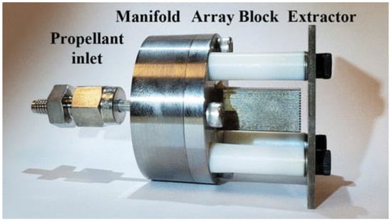
Figure 3.
Photograph of the scaled MEMPS prototype developed by Froberg Aerospace, LLC. Image adapted from ref. [17].
In electrospray mode, a low propellant flow rate is delivered through the microtubes (emitters), while a potential difference is applied between the protrusions and the extractor grid. This configuration enables the extraction and acceleration of droplets and ions to high velocities. In chemical mode, the microtubes are heated, and a larger quantity of propellant is injected into the channels, resulting in the exothermic decomposition of the propellant. The reaction products are then expelled through the extractor grid. Laboratory validation of the MEMPS thruster in electrospray mode has recently been conducted by Lyne et al. [34], demonstrating up to 10 h of continuous operation using a conventional ionic liquid propellant, and up to 4 h with FAM-110A. Additionally, tests in catalytic decomposition mode using FAM-110A have shown stable burn durations of up to 45 s.
Following the approach adopted by Cline et al. [17], the operating parameters of the MEMPS thruster are based on best estimates derived from analytical approximations, chemical decomposition analysis, and subscale experimental data. A single MEMPS unit is assumed to provide a specific impulse of and of thrust in chemical decomposition mode, and a specific impulse of with of thrust at in electrospray mode. In this study, four thruster units are considered, and the corresponding MEMPS performance parameters are summarized in Table 1.

Table 1.
Performance parameters of the reference MEMPS equipped with four thruster units.
To better understand the advantages of the MEMPS system, it is useful to compare it with more traditional single-mode electrical and chemical propulsion systems suitable for CubeSats. For the electrical propulsion comparison, the selected system is the μRIT thruster used in the M-ARGO mission [29,30], with its performance metrics and system mass summarized in Table 2. The RIT μX [35], the smallest member of ArianeGroup’s Radiofrequency Ion Technology (RIT) family suitable for CubeSat applications, offers similar performance to the μRIT used in M-ARGO. For the chemical propulsion comparison, the chosen system is the Busek BGT-5X [13], a green monopropellant thruster that uses hydroxylammonium nitrate (HAN) as its propellant. As shown in the table, the main advantages of the MEMPS system are its lower power requirements and reduced total mass compared to the two single-mode thrusters, along with the added flexibility provided by the use of a single propellant.
Table 2.
Comparison between the MEMPS and traditional electric and chemical single mode propulsion systems for CubeSats.
2.2. Simplified Spacecraft Mass Breakdown
In this section, we present a simplified mass budget model for a MEMPS-propelled CubeSat, drawing on relevant data from the recent literature and adopting a parametric approach to account for variations in solar power availability at different Sun-spacecraft distances. In this context, the reference CubeSat is assumed to be in size, consistent with the proposed M-ARGO mission [29].
The propulsion system is assumed to have a total mass of , based on the specifications provided in [17]. This value accounts for several components, including four thruster units with a combined mass of , a power processing unit (), a propellant tank (), a filter (), a pressure transducer (), five service valves with a total mass of , a check valve (), a burst disc (), propellant lines totaling , a pressurant tank (), and a pressure regulator (). According to ref. [17], the propellant mass is set to .
The mass of the scientific payload is assumed to be , corresponding to the value used for the M-ARGO CubeSat [29]. This payload includes a multispectral imager with a mass of and a laser altimeter weighing , providing enhanced observational and navigational capabilities for the vehicle. Additionally, the small mass of the pressurant—assumed to be molecular nitrogen—is set to .
One of the most critical variables in the mass model is the allocation of power generation and storage components, particularly the solar panels. The MEMPS requires an electrical power of to operate all four propulsion units, while the payload is assumed to consume —a value consistent with the power requirements of the M-ARGO science payload [22,29]. The power budget is directly related to the number of solar panels required, whose mass contribution is analyzed below. According to the specifications of the M-ARGO mission, each solar panel is assumed to generate an electrical power of at a solar distance of 149,597,870 , and has a mass of . The number of panels required at a given maximum heliocentric distance is calculated based on the inverse-square law governing solar flux, as follows:
where is the electric power given by a single panel at distance . The total required number of solar panels is then calculated as
where the symbol represents the ceiling function of the generic term x, so that the total mass of the solar panels is given by
The mass of the spacecraft bus, , is computed as the sum of a baseline value of —which corresponds to the total spacecraft bus mass assumed in ref. [17], including six solar panels—plus the additional mass of solar panels required for the heliocentric mission scenario. The result is
Therefore, the initial total mass of the CubeSat is given by the sum
that is
The results of this parametric mass model are illustrated in Figure 4, which shows the variation in the CubeSat’s total mass, , as a function of the maximum solar distance, , as described by Equation (6). As expected, the mass of the solar panels increases with the heliocentric distance due to the additional power generation requirements, which, in turn, affects the bus mass.
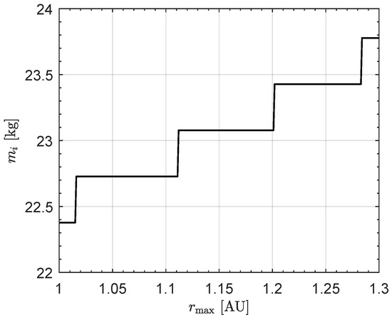
Figure 4.
Variation in the CubeSat’s total mass, , as a function of the maximum solar distance, ; see Equation (6).
3. Mission Description and CubeSat Heliocentric Dynamics
The mission scenario analyzed in this section concerns a classical heliocentric transfer between two circular, Keplerian, and coplanar orbits of specified radii. In this context, we assume that the radius of the CubeSat’s parking orbit (subscript i) is , while the radius of the target circular orbit (subscript f) can be selected within an appropriate range, depending on the characteristics of the CubeSat’s power subsystem in terms of available electric power (see the discussion in Section 2.2). The choice of one astronomical unit (i.e., ) for the initial Sun–CubeSat distance is common in problems of this type, as it approximates a scenario in which the spacecraft begins the heliocentric phase of the mission after completing the Earth escape phase via a parabolic trajectory.
The procedure is, of course, valid for any value of the parking orbit radius. In this two-dimensional scenario, the case corresponds to a so-called orbit raising, while represents a heliocentric orbit lowering. In this context, the magnitude of the CubeSat’s velocity vector at the beginning () and at the end () of the interplanetary flight is given by
where is the gravitational parameter of the Sun.
During the interplanetary transfer, the CubeSat is subject to the gravitational attraction of the Sun and to the thrust generated by the MEMPS. This corresponds to neglecting orbital perturbations and possible uncertainties related to spacecraft dynamics during interplanetary flight, as is typically assumed in preliminary trajectory design. Indeed, this simplified approach allows the designer to investigate a large number of possible transfer trajectories (and mission scenarios) with reduced computational effort. In a subsequent phase of the study, the nominal results obtained are refined using a more accurate dynamical model, applied to a narrower range of potential solutions to the transfer problem. In that part of the study, considering the long flight time associated with the low propulsive acceleration magnitude, the effects of orbital perturbations may influence the nominal shape of the interplanetary trajectory. The thrust vector is modeled following the conventional approach used in preliminary trajectory design involving solar electric propulsion systems. Specifically, the direction of is assumed to be unconstrained and not subject to geometric limitations, such as those potentially imposed by the in-orbit orientation of solar panels. Consequently, the thrust unit vector is considered unconstrained, and the MEMPS-induced thrust is simply expressed as
where T is the thrust magnitude, whose mathematical formulation is consistent with the model discussed in Section 2.1. In this context, we consider a MEMPS configuration comprising four thruster units, as illustrated in the conceptual scheme shown in Figure 2. Note that the potential reduction in available electric power due to solar panel attitude constraints, or limitations in thrust vector orientation, generally leads to a degradation in transfer performance. Therefore, the nominal solution obtained in this case can be considered the optimal (ideal) one for the transfer problem.
As discussed in the Introduction, this configuration enables eight possible thrust levels when the propulsion system is active. The specific impulse of a generic thruster unit operating in chemical mode is with a thrust of , whereas in electric mode, each unit provides a thrust of with a specific impulse of .
According to the model presented in Section 2.1, the total thrust magnitude T and the corresponding total propellant mass flow rate are summarized in Table 3 as functions of the generic operating level . Note that the ninth row of the table (i.e., the case ) represents a fictitious level corresponding to the complete shutdown of the propulsion system, i.e., the typical case in which both T and are zero. In this condition, the CubeSat’s mass remains constant over time, and the spacecraft follows a purely Keplerian arc around the Sun.
Table 3.
Total thrust magnitude (T) and total propellant mass flow rate () as functions of the operating level () for a MEMPS with four thruster units. The ninth row represents a fictitious level (i.e., ) that models the shutdown of the propulsion system.
The thrust magnitude and the propellant mass flow rate as functions of the operating level (Id), for both the electric mode (left sides of the figures) and the chemical mode (right sides of the figures), are also summarized in Figure 5 and Figure 6.
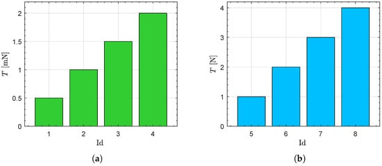
Figure 5.
Thrust magnitude T as a function of the operating level (Id) for the electric and chemical modes of the MEMPS. (a) Electric mode; (b) Chemical mode.
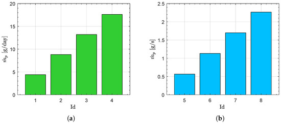
Figure 6.
Propellant mass flow rate as a function of the operating level (Id) for the electric and chemical modes of the MEMPS. (a) Electric mode; (b) Chemical mode.
Accordingly, the CubeSat’s thrust vector is defined by the operating level and the direction of the thrust unit vector . In the two-dimensional scenario considered in this paper, the direction of can be conveniently expressed through the thrust angle , defined as the counterclockwise angle between the Sun–CubeSat line and the direction of the unit vector . Therefore, the scalar control parameters that define the MEMPS-induced thrust vector in the two-dimensional case are given by the dimensionless pair .
The thrust angle and the schematic of a possible interplanetary transfer are shown in Figure 7, together with the heliocentric polar reference frame , in which the polar angle is and the origin O coincides with the Sun’s center of mass. Note that the polar angle is measured counterclockwise from the Sun–CubeSat line at the beginning of the heliocentric transfer, so that at the initial time , one has .
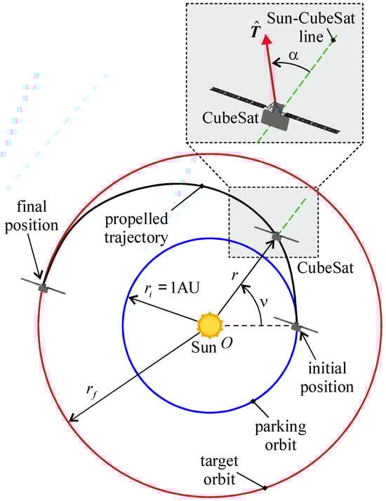
Figure 7.
Thrust angle , thrust unit vector , and heliocentric polar reference frame used to describe the CubeSat’s interplanetary dynamics. In particular, r denotes the radial distance, and is the polar angle measured counterclockwise from the initial Sun–CubeSat line.
The polar reference frame is now used to formulate the CubeSat’s equations of motion in the two-dimensional heliocentric scenario. Denoting by the radial component of the spacecraft’s velocity and by the transverse component, and taking into account the schematic in Figure 7, the equations of motion of the CubeSat in the polar reference frame are written as
where m is the CubeSat’s current mass, and are summarized in Table 3 as functions of the MEMPS operating level Id. The initial conditions, which describe the CubeSat’s motion along the parking orbit of radius , are written as
where is the initial CubeSat mass and is given by Equation (7), while the boundary conditions at the end of the transfer (time instant ) are consistent with the rendezvous with the target circular orbit of radius , viz.
where, again, is given by Equation (7). Note that the final value of the polar angle is left free. During the transfer, the CubeSat’s current mass is constrained by the following condition
where is the total propellant mass stored onboard the spacecraft. This condition is implemented in numerical simulations by forcing the shutdown of the propulsion system—i.e., selecting the thruster’s operating level —when the spacecraft’s local mass drops below the minimum allowed value ; see also the last row of Table 3.
During the flight, we assume that the MEMPS operates exclusively in electric mode, while the chemical mode is reserved for potential trajectory correction maneuvers, which are not considered in the trajectory planning and optimization process described in Section 4. This corresponds to adopting a reduced set of operating levels and imposing the following constraint during the transfer
Considering the constraint expressed by the previous equation, which implies the use of the data summarized in Figure 5a and Figure 6a, the thrust magnitude T and the thrust angle appearing in the equations of motion (9) are obtained using the procedure described in the Section 4.
4. Optimal Trajectory and Guidance Law Design
The values of the two dimensionless scalar control parameters, and , are obtained by solving an optimization problem in which the CubeSat’s transfer trajectory is designed to maximize a given scalar performance index J [36,37]. In particular, two different performance indices are considered in this section: the flight time and the final mass of the CubeSat. Specifically, the maximization of the performance index , defined as
yields the minimum-time transfer trajectories, which are typically studied as a preliminary step toward computing the trajectory that minimizes propellant consumption. Once the minimum flight time has been determined, the transfer trajectories that minimize propellant consumption are obtained by maximizing the performance index , defined as
by selecting (and fixing) a flight time greater than the value obtained in the minimum-time transfer analysis, i.e., . This procedure is consistent with the approach used in ref. [10] for conventional electric propulsion systems.
The maximization of the performance index J is carried out using an indirect method [38,39], in which, taking Equation (9) into account, the Hamiltonian function is defined as
where are the variables adjoint to the states of the CubeSat during the transfer. The time derivative of the generic adjoint variable is given by
the right term of which can be easily calculated by using the expression of the Hamiltonian function given by Equation (16). In this context, note that , so that the adjoint variable is a constant of motion. The differential system composed of the equations of motion (9) and the Euler–Lagrange Equation (17) is numerically integrated using a PECE solver based on the Adams–Bashforth–Moulton method, implemented in MATLAB 2024’s built-in function ode113 [40]. In this regard, a tolerance of is set in the routine.
The function is also used to express the transversality condition, which provides the remaining boundary constraints required to complete the two-point boundary value problem associated with the optimization process. The boundary value problem is solved using an automatic routine based on the classical single shooting method [41], with a tolerance on the final value of the Euclidean norm of the error set to less than . In this context, when the performance index to be maximized is defined by Equation (14), and the flight time is among the unknowns, the transversality condition yields
Conversely, when the performance index is defined by Equation (15)—that is, when the propellant mass is minimized by fixing the flight time such that —the transversality condition provides
Observe that, in both rapid and minimum-propellant-mass transfers, the final value of the adjoint variable is zero. This outcome is due to the fact that the CubeSat’s polar angle is unconstrained in the mission scenario analyzed here. Recalling that is a constant of motion, it follows that throughout the entire transfer. Therefore, this adjoint variable can be eliminated from the two-point boundary value problem. The latter is solved using a procedure that parallels the approach recently adopted in ref. [42], which enables a rapid and accurate estimation of the initial values of the unknown adjoint variables through a semi-analytical method. Indeed, the semi-analytical procedure used to estimate the initial value of the unknown adjoint variable is based on the results discussed in the recent study [42], where the initial values of certain costates and the flight time in a classical circle-to-circle transfer are linked to the geometric characteristics of the transfer (i.e., the initial and final radii) and the design features of the continuous-thrust propulsion system (such as the magnitude of the propulsive acceleration at the beginning of the transfer). In any case, even a trial-and-error procedure can be employed to obtain the unknown initial costates.
Note that the two-point boundary value problem requires determining the initial values (i.e., the values at the starting time ) of the adjoint variables and the flight time in the minimum-time problem, whereas the solution of the minimum-propellant-mass problem requires only the determination of the initial values of , since is assigned.
The optimal guidance law, expressed in terms of the time variation of the thrust angle and the selection of the MEMPS operating level Id, is obtained by applying the classical Pontryagin’s Maximum Principle [43], which requires maximizing the Hamiltonian function at each time instant [44,45]. Taking into account the expression of given in Equation (16), and assuming that the MEMPS is turned on (, see Table 3), i.e., assuming that , the necessary condition yields the well-known result for a spacecraft propelled by a solar electric propulsion system in which the thrust vector direction is unconstrained, namely,
Paralleling the procedure described in ref. [46], in order to compute the optimal operating level—namely, the (optimal) value of Id that maximizes the Hamiltonian function—we isolate the portion of that explicitly depends on the control term Id. In this regard, keeping in mind Equation (20), and starting from Equation (16), we obtain a reduced form of the Hamiltonian function as
in which both T and are functions of the operating level Id, as described in Table 3 for the electric mode. Therefore, at any given time instant in which the values of the adjoint variables are known, the optimal value of is obtained simply by selecting—through a standard sorting procedure [41]—the operating level that yields the maximum of among the four available options in the electric mode. If the maximum value of obtained in this way is negative, then is selected, which turns off the MEMPS and thereby effectively maximizes the Hamiltonian function . Otherwise, the selected operating level is retained and the MEMPS remains active. It is worth noting that the expressions of both the optimal thrust angle and the reduced Hamiltonian function are consistent with those derived in ref. [46].
5. Numerical Simulations and Mission Applications
According to the model presented in Section 2.2, consider a MEMPS-propelled CubeSat with a payload mass —a value consistent with the payload mass of the proposed M-ARGO CubeSat [29]—and a total propellant mass , which matches the value used in ref. [17] for a mission to the Moon. Assume a target orbit radius in the range , with . This range corresponds to a variation from the radius of the parking orbit. Moreover, the assumed range of is consistent with the interval adopted in ref. [31].
In this scenario, the mathematical model described in Section 2.2 yields an initial mass (rounded to in the simulation) and the mass distribution shown in Figure 8. Specifically, the CubeSat considered in the numerical simulations includes a pressurant mass , a MEMPS mass , and a bus mass .
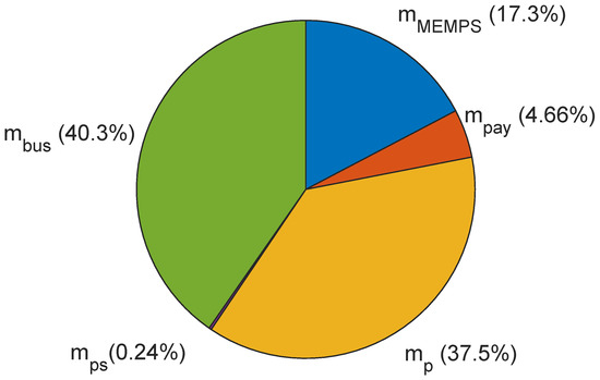
Figure 8.
Mass distribution of the interplanetary CubeSat used in the numerical simulations, with a total initial mass of and a propellant mass of .
Consider now a rapid transfer scenario, in which the CubeSat’s interplanetary trajectory minimizes (or maximizes) the flight time—or, equivalently, the performance index defined in Equation (14). Using a step size of to scan the admissible range of the target radius , the numerical solution of the optimal control problem described in the previous section yields the function , shown in Figure 9, which illustrates the variation in the minimum flight time with respect to the radius of the final circular orbit. Note that the curves in Figure 9 are obtained by solving 80 optimization problems.
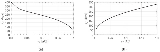
Figure 9.
Minimum flight time, , as a function of the radius of the target circular orbit, for a CubeSat with a total initial mass of and a propellant mass of . (a) Orbit-lowering scenario; (b) Orbit-raising scenario.
The corresponding propellant mass required to complete the transfer, expressed as a percentage of the total propellant mass stored onboard the CubeSat (), is shown in Figure 10. It is interesting to note that the curve representing the propellant expenditure mass fraction closely resembles that of the flight time shown in Figure 9. This result is not surprising, as numerical simulations indicate that the MEMPS remains active throughout the entire transfer, operating at a nearly constant level of , which corresponds to the maximum thrust magnitude in electric mode (see Table 3). Accordingly, in this case, the required propellant mass is obtained as the product of the flight time and the propellant mass flow rate associated with the operating level.
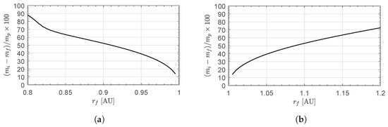
Figure 10.
Propellant expenditure mass fraction as a function of the radius of the target circular orbit, for a CubeSat with a total initial mass of and a propellant mass of . (a) Orbit-lowering scenario; (b) Orbit-raising scenario.
For example, Figure 9 and Figure 10 show that a two-dimensional circle-to-circle transfer between an initial solar distance of and a final solar distance of can be completed in approximately , with a propellant expenditure of —or about of . This implies that more than of residual propellant remains available, which can be used, for instance, to perform orbital correction maneuvers using the MEMPS chemical mode. Conversely, a transfer to requires about of the total propellant mass, leaving a residual amount slightly below .
The time-optimal transfer trajectories for are shown in Figure 11, while Figure 12 presents the time evolution of the optimal thrust angle along the CubeSat’s trajectory. It is worth noting that the optimal transfer trajectory completes one revolution around the Sun when , whereas in the other three cases, the final value of the polar angle is less than .
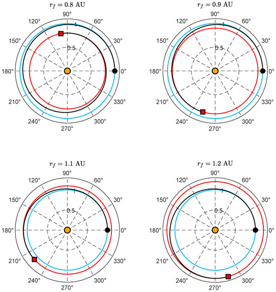
Figure 11.
Minimum-time transfer trajectory as a function of the final radius, . Blue line → parking circular orbit; red line → target circular orbit; black line → transfer trajectory; black dot → starting point; red square → arrival point; orange circle → the Sun.

Figure 12.
Optimal temporal variation of the thrust angle as a function of the final radius, . Black dot → starting point; red square → arrival point.
In particular, it is observed that the thrust angle value, as expected, is negative in the case of orbit lowering, since the propelling acceleration acts to reduce the specific mechanical energy of the osculating orbit. A specular behavior is observed in the case of orbit raising, where the thrust angle remains positive throughout the flight. Furthermore, it is noteworthy that the excursion of the optimal thrust angle decreases as the distance between the target orbit and the parking orbit increases. This aspect, combined with the information regarding the sign of , suggests that a semi-analytical procedure could be developed for accurately estimating the transfer performance in this classical scenario of transfer between circular and coplanar orbits, as proposed in ref. [47]. This promising direction certainly represents a possible extension of the work presented in this paper.
5.1. Case of Failure of Multiple Thruster Units
The numerical results presented in the previous section indicate that a MEMPS-propelled CubeSat with a mass of approximately , equipped with four thruster units and carrying of propellant, is potentially capable of performing a circular orbit raising (or lowering) within the range in less than 400 days. This outcome is made possible by activating all thruster units during the transfer, thereby achieving the maximum local thrust magnitude in electric mode.
At this point, however, a natural question arises: what is the transfer performance (i.e., the minimum flight time) if only thruster units are available during the flight? In fact, the case corresponds to the scenario already analyzed in the main part of this paper. This new situation can model a failure scenario in which one or more thruster units become inoperative before the start of the heliocentric transfer. For instance, the case represents the failure of a single thruster unit, leaving only three units available to execute the orbital transfer.
The mathematical model describing the case can be directly derived from that discussed in Section 4, by considering a reduced version of the thrust table (Table 3), in which the number of available active units (in electric mode, of course) is limited to . The numerical results corresponding to the failure of one or more thruster units are shown in Figure 13 and Figure 14.
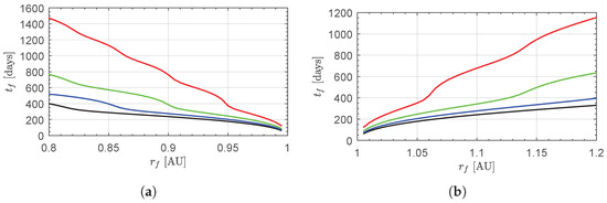
Figure 13.
Case of failure of one or more thruster units: minimum flight time, , as a function of and . (a) Orbit-lowering scenario; (b) Orbit-raising scenario. Black line → design case with four thruster units; blue line →; green line →; red line →.
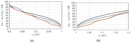
Figure 14.
Case of failure of one or more thruster units: required propellant mass (as a percentage of ) as a function of and . The legend is provided in the caption of Figure 13. (a) Orbit-lowering scenario; (b) Orbit-raising scenario.
In particular, Figure 13 clearly shows that the number of propulsion units has a significant impact on the flight time, especially for small values of n and when the target orbit radius differs substantially from . For example, when and , the flight time is —that is, an increase of compared to the nominal case with four thruster units. Conversely, if , the flight time rises to , which is approximately times the value obtained in the design scenario.
On the other hand, Figure 14 indicates that the value of n has a relatively minor impact on the propellant mass consumed, although percentage variations of up to are observed for target orbits close to the parking orbit. The extended time of flight also results in a more complex transfer trajectory, involving multiple revolutions around the Sun before reaching the target orbit. This aspect is illustrated in Figure 15, which shows the transfer trajectory and the time evolution of the thrust angle for the case and . In both cases shown in Figure 15, the MEMPS operating level remains constant throughout the flight and is equal to , as expected.
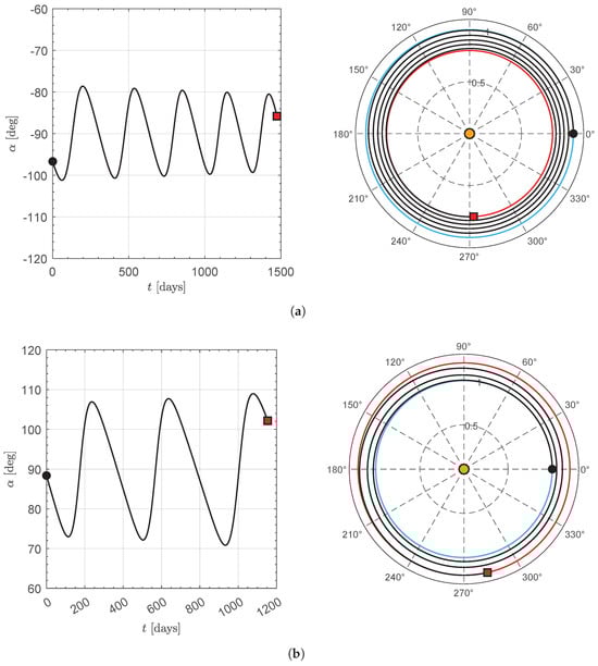
Note that the thrust angle oscillates around (or ) during orbit raising (or lowering), in agreement with the analytical results reported in ref. [47]. Additionally, the number of complete revolutions is 2 in the case of orbit raising and 4 in the case of orbit lowering.
5.2. Transfer of Minimum Propellant Mass
In this final part of the section, the case of a circle-to-circle orbit transfer minimizing the propellant mass is considered. Specifically, CubeSat transfer trajectories with a fixed flight time greater than the minimum admissible value—aimed at maximizing the performance index defined in Equation (15)—are simulated using the mathematical model described in Section 2. To reduce computational effort, only the orbit-lowering scenario with and all thruster units available is reported below, although other scenarios yield conceptually similar results. Recall that the solution to the minimum flight time problem gives a transfer duration of , with a required propellant mass of , corresponding to approximately of the total available propellant mass (i.e., ).
In this mission scenario—namely, orbit lowering with a final radius of —consider a fixed flight time within the interval , corresponding to a increase over the minimum flight time. In this case, the optimization process yields the required propellant mass (expressed as a percentage of ) as a function of the fixed flight time , as shown in Figure 16.
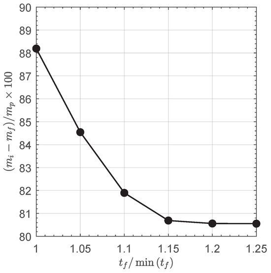
Figure 16.
Optimal propellant expenditure mass fraction as a function of flight time, , during an orbit-lowering maneuver with .
From Figure 16, it can be observed that a increase in flight time allows for a reduction of approximately in propellant mass compared to the value obtained in the rapid transfer case. Furthermore, the shape of the graph suggests a settling trend, indicating that the required propellant mass becomes largely insensitive to further increases in flight time.
6. Conclusions
This paper has presented a simplified approach for studying the optimal transfer trajectories of a typical CubeSat equipped with a monopropellant electrospray multimode propulsion system. In particular, using an optimization method based on the calculus of variations, the optimal performance of the small spacecraft has been evaluated in a heliocentric framework, considering a classical mission scenario: the circle-to-circle orbit transfer. Within this context, the paper adopts a simplified thrust model and mass distribution to investigate the variation in transfer performance (in terms of minimum flight time and required propellant mass) as a function of the characteristics of the target circular orbit. Numerical simulations indicate that a heliocentric orbit raising, increasing the initial solar distance by , can be achieved with a flight time of approximately 11 months and a propellant consumption slightly below .
The parametric study of optimal performance in this important mission scenario also reveals an interesting analogy with semi-analytical results recently reported in the literature, which suggest the possibility of estimating optimal performance through an approximate approach. In this context, a first potential extension of this work involves a detailed investigation of this intriguing aspect related to the shape of the optimal control law, with the aim of identifying a semi-analytical model for accurately evaluating the performance of a vehicle powered by such an advanced multimode propulsion system. Another possible extension concerns the analysis of potential failures of one or more thruster units during the transfer, to assess the impact of thrust reduction on mission performance and optimal trajectory. Indeed, the final part of the previous section highlighted that a reduction in the number of active propulsion units at the beginning of the transfer significantly affects the total flight time, compared to the results obtained under nominal conditions.
Other possible extensions of this work include: the refinement of the thrust model through the inclusion of attitude control system constraints; the generalization to a three-dimensional case, which allows heliocentric plane change maneuvers to be considered in mission design; the study of uncertainties in modeling the thrust magnitude or the propellant mass flow rate; and a general case in which chemical propulsion is also employed in the design of the optimal transfer trajectory.
Author Contributions
Conceptualization, A.A.Q.; methodology, A.A.Q., M.B., and G.B.; software, A.A.Q.; writing—original draft preparation, A.A.Q., M.B., and G.B.; writing—review and editing, A.A.Q., M.B., and G.B. All authors have read and agreed to the published version of the manuscript.
Funding
This research received no external funding.
Institutional Review Board Statement
Not applicable.
Informed Consent Statement
Not applicable.
Data Availability Statement
The original contributions presented in the study are included in the article; further inquiries can be directed to the first author.
Conflicts of Interest
The authors declare no conflict of interest.
Abbreviations
The following abbreviations are used in this manuscript:
| reduced set of operating levels | |
| Hamiltonian function | |
| part of the Hamiltonian function which depends on Id | |
| Id | operating level |
| J | performance index |
| performance index in the minimum propellant transfer scenario | |
| performance index in the rapid transfer scenario | |
| m | CubeSat mass [kg] |
| propellant mass flow rate [kg/s] | |
| mass of the bus [kg] | |
| mass of the MEMPS [kg] | |
| mass of the pressurant [kg] | |
| total propellant mass [kg] | |
| mass of the scientific payload [kg] | |
| mass of the solar panels [kg] | |
| n | number of active thruster units in case of failures, with |
| number of required solar panels | |
| O | Sun’s center of mass |
| electric power required by the MEMPS [W] | |
| electric power required by the payload [W] | |
| electric power given by the solar panels at maximum solar distance [W] | |
| electric power given by a single solar panel at [W] | |
| r | Sun–CubeSat distance [AU] |
| heliocentric polar reference frame | |
| T | thrust magnitude [N] |
| MEMPS-induced thrust vector [N] | |
| thrust unit vector | |
| t | time [days] |
| v | CubeSat’s velocity magnitude [km/s] |
| radial component of the CubeSat’s velocity vector [km/s] | |
| circumferential component of the CubeSat’s velocity vector [km/s] | |
| thrust angle [rad] | |
| adjoint to CubeSat’s state variable j | |
| Sun’s gravitational parameter [km3/s2] | |
| CubeSat’s polar angle [rad] | |
| Subscripts | |
| i | initial, parking orbit |
| f | final, target orbit |
| Superscripts | |
| · | time derivative |
References
- Rovey, J.L.; Lyne, C.T.; Mundahl, A.J.; Rasmont, N.; Glascock, M.S.; Wainwright, M.J.; Berg, S.P. Review of multimode space propulsion. Prog. Aerosp. Sci. 2020, 118, 100627. [Google Scholar] [CrossRef]
- Arya, V.; Taheri, E.; Junkins, J.L. Low-Thrust Gravity-Assist Trajectory Design Using Optimal Multimode Propulsion Models. J. Guid. Control Dyn. 2021, 44, 1280–1294. [Google Scholar] [CrossRef]
- Quarta, A.A.; Izzo, D.; Vasile, M. Time-Optimal Trajectories to Circumsolar Space Using Solar Electric Propulsion. Adv. Space Res. 2013, 51, 411–422. [Google Scholar] [CrossRef]
- Marcucci, M.G.; Polk, J.E. NSTAR Xenon Ion Thruster on Deep Space 1: Ground and flight tests. Rev. Sci. Instrum. 2000, 71, 1389–1400. [Google Scholar] [CrossRef]
- Polk, J.; Chaplin, V.; Anderson, J.; Yim, J.; Soulas, G.; Williams, G.; Shastry, R. Modeling grid erosion in the NEXT ion thruster using the CEX2D and CEX3D codes. J. Electr. Propuls. 2023, 2, 14. [Google Scholar] [CrossRef]
- Mani, K.V.; Cervone, A.; Topputo, F. Combined Chemical–Electric Propulsion for a Stand-Alone Mars CubeSat. J. Spacecr. Rocket. 2019, 56, 1816–1830. [Google Scholar] [CrossRef]
- Pollard, J.E.; Cohen, R.B. Hybrid electric chemical propulsion. J. Propuls. Power 1986, 2, 124–128. [Google Scholar] [CrossRef]
- Ceriotti, M.; McInnes, C.R. Hybrid solar sail and solar electric propulsion for novel Earth observation missions. Acta Astronaut. 2011, 69, 809–821. [Google Scholar] [CrossRef][Green Version]
- Baig, S.; McInnes, C.R. Artificial Three-Body Equilibria for Hybrid Low-Thrust Propulsion. J. Guid. Control Dyn. 2008, 31, 1644–1655. [Google Scholar] [CrossRef]
- Mengali, G.; Quarta, A.A. Tradeoff performance of hybrid low-thrust propulsion system. J. Spacecr. Rocket. 2007, 44, 1263–1270. [Google Scholar] [CrossRef]
- Cline, B.C.; Pascarella, A.; Woollands, R.M.; Rovey, J.L. Indirect optimal control techniques for multimode propulsion mission design. Acta Astronaut. 2024, 223, 759–776. [Google Scholar] [CrossRef]
- Taheri, E.; Junkins, J.L. Generic Smoothing for Optimal Bang-Off-Bang Spacecraft Maneuvers. J. Guid. Control Dyn. 2018, 41, 2470–2475. [Google Scholar] [CrossRef]
- Lemmer, K. Propulsion for CubeSats. Acta Astronaut. 2017, 134, 231–243. [Google Scholar] [CrossRef]
- Alnaqbi, S.; Darfilal, D.; Swei, S.S.M. Propulsion technologies for CubeSats. Aerospace 2024, 11, 502. [Google Scholar] [CrossRef]
- Klesh, A.; Clement, B.; Colley, C.; Essmiller, J.; Forgette, D.; Krajewski, J.; Marinan, A.; Martin-Mur, T. MarCO: Early operations of the first CubeSats to Mars 2018. In Proceedings of the Small Satellite Conference (SmallSat 2018), Logan, UT, USA, 4–9 August 2018. [Google Scholar]
- Tsay, M.; Model, J.; Barcroft, C.; Frongillo, J.; Zwahlen, J.; Feng, C. Integrated testing of iodine bit-3 rf ion propulsion system for 6u cubesat applications. In Proceedings of the 35th International Electric Propulsion Conference Georgia Institute of Technology, Atlanta, GA, USA, 8–12 October 2017; pp. 8–12. [Google Scholar]
- Cline, B.C.; Parker, K.I.; Rosales, J.J.; Rovey, J.L.; West, S.T. Lunar SmallSat Missions with Chemical-Electrospray Multimode Propulsion. J. Spacecr. Rocket. 2024, 61, 1032–1046. [Google Scholar] [CrossRef]
- Rovey, J.L.; Koizumi, H. Dual-mode propulsion systems for SmallSats. In Next Generation CubeSats and SmallSats; Elsevier: Amsterdam, The Netherlands, 2023; pp. 447–484. [Google Scholar] [CrossRef]
- Berg, S.P.; Rovey, J.L. Assessment of Multimode Spacecraft Micropropulsion Systems. J. Spacecr. Rocket. 2017, 54, 592–601. [Google Scholar] [CrossRef]
- Mallalieu, P.; Jugroot, M. Multimodal electrospray thruster for small spacecraft: Design and experimental characterization. J. Electr. Propuls. 2024, 3, 12. [Google Scholar] [CrossRef]
- Bruno, A.R.; Schroeder, M.R.; Lozano, P.C. Characterization of Electrospray Thrusters with HAN-Based Monopropellants for Multimode Propulsion Applications. In Proceedings of the AIAA SCITECH 2022 Forum, San Diego, CA, USA, 3–7 January 2022. [Google Scholar] [CrossRef]
- Walker, R.; Koschny, D.; Bramanti, C. Design and Development of a Multi-Mode Monopropellant Electrospray. In Proceedings of the Small Satellite Conference, Logan, UT, USA, 6–11 August 2016. [Google Scholar]
- Berg, S.P.; Rovey, J.L. Assessment of imidazole-based ionic liquids as dual-mode spacecraft propellants. J. Propuls. Power 2013, 29, 339–351. [Google Scholar] [CrossRef]
- Spence, D.; Ehrbar, E.; Rosenbald, N.; Demmons, N.; Roy, T.; Hoffman, S.; Williams, W.D.; Tsay, M.; Zwahlen, J.; Hohman, K.; et al. Electrospray Propulsion Systems for Small Satellites and Satlets. In Proceedings of the AIAA SPACE 2013 Conference and Exposition, San Diego, CA, USA, 10–12 September 2013. [Google Scholar] [CrossRef]
- Marrese-Reading, C.; Arestie, S.; Landau, D. Electrospray Thrusters for Smallsat Missions. In Proceedings of the Small Satellite Conference, Logan, UT, USA, 5–10 August 2023. [Google Scholar]
- Falcone, G.; Engel, D.L.; Cortinovis, M.; Ryan, C.N.; Rovey, J.L.; Putnam, Z.R.; Berg, S.; Lembeck, M. Mission Performance Assessment of Multimode Propulsion for Satellite Servicing Applications. In Proceedings of the 2022 IEEE Aerospace Conference (AERO), Big Sky, MT, USA, 5–12 March 2022; pp. 1–19. [Google Scholar] [CrossRef]
- Qi, Y.; Xu, S.; Qi, R. Lunar flyby transfers between libration point orbits. Mon. Not. R. Astron. Soc. 2017, 468, 2265–2282. [Google Scholar] [CrossRef]
- Zhou, X.; Li, X.; Huo, Z.; Meng, L.; Huang, J. Near-Earth Asteroid Surveillance Constellation in the Sun-Venus Three-Body System. Space Sci. Technol. 2022, 2022, 9864937. [Google Scholar] [CrossRef]
- Walker, R.; Koschny, D.; Bramanti, C. Miniaturised Asteroid Remote Geophysical Observer (M-ARGO): A stand-alone deep space CubeSat system for low cost science and exploration missions. In Proceedings of the 6th Interplanetary CubeSat Workshop, Cambridge, UK, 30 May 2017. [Google Scholar]
- Walker, R.; Binns, D.; Bramanti, C.; Casasco, M.; Concari, P.; Izzo, D.; Feili, D.; Fernandez, P.; Fernandez, J.G.; Hager, P.; et al. Deep-space CubeSats: Thinking inside the box. Astron. Geophys. 2018, 59, 5.24–5.30. [Google Scholar] [CrossRef]
- Topputo, F.; Wang, Y.; Giordano, C.; Franzese, V.; Goldberg, H.; Perez-Lissi, F.; Walker, R. Envelop of reachable asteroids by M-ARGO CubeSat. Adv. Space Res. 2021, 67, 4193–4221. [Google Scholar] [CrossRef]
- Quarta, A.A.; Mengali, G. Minimum-Time Space Missions with Solar Electric Propulsion. Aerosp. Sci. Technol. 2011, 15, 381–392. [Google Scholar] [CrossRef]
- Berg, S.P.; Rovey, J.L. Assessment of high-power electric multi-mode spacecraft propulsion concepts. In Proceedings of the 33th International Electric Propulsion Conference, Washington, DC, USA, 6–10 October 2013. [Google Scholar]
- Lyne, C.T.; Rovey, J.; Berg, S.P. Monopropellant-Electrospray Multimode Thruster Testing Results: Electrospray Mode. In Proceedings of the AIAA Propulsion and Energy 2021 Forum, Virtual Event, 9–11 August 2021. [Google Scholar] [CrossRef]
- Leiter, H.; Altmann, C.; Porst, J.; Lauer, D.; Berger, M.; Rath, M. Six decades of thrust-the Ariane Group radiofrequency ion thrusters and systems family. In Proceedings of the 35th International Electric Propulsion Conference, Atlanta, GA, USA, 8–12 October 2017. [Google Scholar]
- Shirazi, A.; Ceberio, J.; Lozano, J.A. Spacecraft trajectory optimization: A review of models, objectives, approaches and solutions. Prog. Aerosp. Sci. 2018, 102, 76–98. [Google Scholar] [CrossRef]
- Chai, R.; Savvaris, A.; Tsourdos, A.; Chai, S.; Xia, Y. A review of optimization techniques in spacecraft flight trajectory design. Prog. Aerosp. Sci. 2019, 109, 100543. [Google Scholar] [CrossRef]
- Bryson, A.E.; Ho, Y.C. Applied Optimal Control; Hemisphere Publishing Corporation: New York, NY, USA, 1975; Chapter 2; pp. 71–89. ISBN 0-891-16228-3. [Google Scholar]
- Stengel, R.F. Optimal Control and Estimation; Dover Books on Mathematics, Dover Publications, Inc.: New York, NY, USA, 1994; pp. 222–254. [Google Scholar]
- Shampine, L.F.; Reichelt, M.W. The MATLAB ODE Suite. SIAM J. Sci. Comput. 1997, 18, 1–22. [Google Scholar] [CrossRef]
- Yang, W.Y.; Cao, W.; Kim, J.; Park, K.W.; Park, H.H.; Joung, J.; Ro, J.S.; Hong, C.H.; Im, T. Applied Numerical Methods Using MATLAB; John Wiley & Sons, Inc.: Hoboken, NJ, USA, 2020; Chapter 1; pp. 14–15. [Google Scholar]
- Quarta, A.A. Initial costate approximation for rapid orbit raising with very low propulsive acceleration. Appl. Sci. 2024, 14, 1124. [Google Scholar] [CrossRef]
- Ross, I.M. A Primer on Pontryagin’s Principle in Optimal Control; Collegiate Publishers: San Francisco, CA, USA, 2015; Chapter 2; pp. 127–129. [Google Scholar]
- Prussing, J.E. Spacecraft Trajectory Optimization; Cambridge University Press: Cambridge, UK, 2010; Chapter 2; pp. 16–36. [Google Scholar] [CrossRef]
- Prussing, J.E. Optimal Spacecraft Trajectories; Oxford University Press: Oxford, UK, 2018; Chapter 4; pp. 32–40. [Google Scholar]
- Quarta, A.A. Preliminary Trajectory Analysis of CubeSats with Electric Thrusters in Nodal Flyby Missions for Asteroid Exploration. Remote Sens. 2025, 17, 513. [Google Scholar] [CrossRef]
- Quarta, A.A. Continuous-Thrust Circular Orbit Phasing Optimization of Deep Space CubeSats. Appl. Sci. 2024, 14, 7059. [Google Scholar] [CrossRef]
Disclaimer/Publisher’s Note: The statements, opinions and data contained in all publications are solely those of the individual author(s) and contributor(s) and not of MDPI and/or the editor(s). MDPI and/or the editor(s) disclaim responsibility for any injury to people or property resulting from any ideas, methods, instructions or products referred to in the content. |
© 2025 by the authors. Licensee MDPI, Basel, Switzerland. This article is an open access article distributed under the terms and conditions of the Creative Commons Attribution (CC BY) license (https://creativecommons.org/licenses/by/4.0/).