Article

Effects of Heat on Silicone Breast Implants: In Situ and Modeling Analysis

1
School of Electrical Engineering, Afeka Tel-Aviv Academic College of Engineering, Tel-Aviv 6910717, Israel
2
Department of Plastic and Reconstructive Surgery, Sheba Medical Center, Ramat-Gan, Affiliated with the School of Medicine, Tel-Aviv University, Tel-Aviv 52621, Israel
3
Talpiot Leadership Program, Sheba Medical Center, Ramat-Gan 52621, Israel
4
Institute for Health Research, University of Notre Dame, Fremantle, WA 6160, Australia
5
School of Medical Engineering, Afeka Tel-Aviv Academic College of Engineering, Tel-Aviv 6910717, Israel
6
School of Mechanical Engineering, Afeka Tel-Aviv Academic College of Engineering, Tel-Aviv 6910717, Israel
7
School of Nursing, Paramedicine and Healthcare Sciences, Charles Sturt University, Bathurst, NSW 2795, Australia
8
School of Nursing, Midwifery and Social Sciences, CQUniversity, Sydney, NSW 2000, Australia
9
Townsville University Hospital, Townsville, QLD 4810, Australia
10
College of Medicine and Dentistry, James Cook University, Townsville, QLD 4810, Australia
*
Author to whom correspondence should be addressed.
These authors contributed equally to this work.
Appl. Sci. 2025, 15(16), 8831; https://doi.org/10.3390/app15168831
Submission received: 31 May 2025 / Revised: 25 July 2025 / Accepted: 28 July 2025 / Published: 11 August 2025
(This article belongs to the Special Issue Thermal Imaging Techniques in Biomedical Applications)

Abstract

Women with silicone-gel breast implants may be at risk of burns on reconstructed tissue due to inadequate blood flow and heat transfer after mastectomy. This study employed thermal imaging and numerical simulations to examine the impact of external heat on silicone breast implants. By applying infrared radiation across three spectrum ranges, detailed thermal maps were created and analyzed with MATLAB software (Mathworks, Natick, MA, USA) version release 2020b. Implants were heated to simulate body and external conditions, enabling thermal imaging to assess temperature distribution. The Finite Element Method was utilized for heat transfer simulations. Our results indicated deeper thermal penetration in the implanted breast model compared to a standard model. This study highlights thermal imaging as a reliable, non-invasive method to evaluate implant responses to heat and suggests strategies to reduce heat-related injuries in patients with breast reconstruction. This method has the potential for comfortable and safe home monitoring of patients using handheld thermal imaging cameras that are now available as attachments for smartphones.

1. Introduction

Silicone-gel breast implants are used for reconstructive or aesthetic purposes. Reconstructive implants restore breast appearance after mastectomy, correct congenital or traumatic defects, or address asymmetries, often improving psychological well-being, self-esteem, and body image [1,2]. Aesthetic implants enhance breast size or shape through augmentation or mastopexy. Implants can be placed above (prepectoral) or below (subpectoral) the pectoralis major muscle, with reconstruction performed immediately or delayed after mastectomy.
Implant complications include general surgical risks like infection, bleeding, or delayed healing and implant-specific issues such as capsular contracture, rupture, or malposition [3,4]. Risk factors include smoking, high BMI, older age, poor skin quality, chemotherapy, and radiotherapy [5,6,7]. Complication rates vary by mastectomy type [8,9], implant type [10], bilateral surgery [11], and the weight of the mastectomy [12]. Comparing complication rates is challenging due to differences in reconstruction techniques, surgeon experience, patient health, and follow-up duration [13,14,15]. Studies report noninfectious complications in 10.3% of implant-based mastectomies [16] and surgical site infections in 8.9% (immediate) and 5.7% (delayed) of reconstructions [17].
The thermo-physical behavior of silicone-gel breast implants in response to external heat exposure is not well understood, and there is limited research quantifying the risks of thermal injury associated with these implants [18]. Factors such as reduced sensation, poor blood circulation, and altered heat transfer in reconstructed breast tissue may intensify burns, thereby increasing the risk of unnoticed thermal damage [19]. A review of 59 cases revealed that the primary causes of burns in reconstructed breasts were heat conduction (63%), solar radiation (32%), and convection (5%) [18]; however, it did not provide a detailed analysis of how the thermal properties of implants affect these injuries.
This study presents a novel approach that combines in situ thermal imaging and numerical modeling to quantitatively assess the impact of external heat on silicone-gel implants. By clarifying their thermo-physical properties, this research aims to address the existing knowledge gap and inform strategies to prevent thermal injuries.

2. Materials and Methods

2.1. In Situ Experiment—Thermal Imaging

This part describes the experimental work conducted in the laboratory using the implants and thermal imaging.

2.1.1. The Experimental System

Thermal imaging is a non-invasive and painless imaging technique that relies on the detection of infrared (IR) radiation emitted by an object due to its temperature. The resulting thermal image of an object serves as a heat map of the object’s surface temperature distribution and does not expose the imaged object to ionizing radiation.
The human eye is sensitive to visible light, which is a form of electromagnetic radiation with wavelengths ranging from 400 nm to 700 nm. IR wavelengths range from 700 nm to 1 mm and are invisible to the human eye. Thermal imaging cameras are mechanistically unique as they form an image using infrared radiation rather than visible light. Thermal imaging uses three ranges of the IR spectrum: (i) near-IR (750–2500 nm); (ii) mid-IR (2500–5000 nm); and (iii) far-IR (5000–15,000 nm). Most biomedical IR imaging modalities utilize the near-IR spectrum for both structural and functional imaging. In contrast, the far-IR spectrum is primarily employed for capturing the thermal emission of tissues.
The thermal camera used in this project was the Optris Xi 400 (Berlin, Germany), which was connected to a computer to facilitate detailed filming of the implant’s response during the experiments. This setup allowed for precise monitoring and recording of thermal data, which was crucial for accurate analysis (see Figure 1).
If an IR camera is calibrated correctly, the surface temperature distribution can be recovered from the detected radiation. IR imaging can be either passive or active; passive imaging refers to capturing the representation of an object’s spontaneously emitted radiation, while active imaging addresses capturing the representation of a thermal contrast (difference) in an object’s emitted radiation caused by either heating or cooling. Entropy, skewness, and kurtosis are texture parameters relevant to image processing, which we analyzed in the current experiment. Recently, thermal imaging has been utilized in medical diagnosis. Previous studies have shown its capability to characterize physiological and pathological conditions in various organs, including the breast [20,21,22]. In assessing the thermal behavior of silicone-gel breast implants, our study utilizes thermal imaging techniques similar to those reported in our prior study [23], which first characterized the thermal profiles of three specific implant sizes. We acknowledge the foundational work of this earlier research, which has paved the way for more detailed investigations into the thermal properties of these materials. While our use of thermal imaging is not novel in itself, our study extends previous work by providing a more detailed analysis of the thermal response. This includes a comprehensive examination of the implications of these thermal properties for patient safety and clinical outcomes.
The studied silicone-gel implants had a textured, round, and highly cohesive silicone shell. They included the following: (i) a 350 cubic centimetres (cc) MemoryGel® implant, high-profile, with a diameter of 11.7 cm and a projection of 4.8 cm (Mentor® catalog #324-4350; Mentor Worldwide LLC, Irvine, CA, USA); (ii) a 300 cc MemoryGel® implant, moderate-plus profile, with a diameter of 12 cm and a projection of 3.6 cm (Mentor® catalog #324-5300; Mentor Worldwide LLC, Irvine, CA, USA); and (iii) a 280 cc implant, medium profile, with a diameter of 12.3 cm and a projection of 3.7 cm (Eurosilicone® catalog #35R280; GC Aesthetics, La Ciotat, France). These implants were chosen for their availability and their representation of common volumes and structures used in clinical settings.

2.1.2. The Experiment Protocol

The lab temperature was set at 25 °C. The experiment consisted of the following sequence of steps: (i) the silicone implant was placed on a heating surface set at 37 °C, which simulates internal body temperature; (ii) after twenty minutes, a hot water bottle containing boiling water (around 100 °C) with an external temperature of 65 °C was placed on the implant for 30 min before being removed; (iii) the implant was photographed by a thermal camera every 10 min for 40 min; (iv) the implant was then placed on a surface at room temperature (25 °C) until it returned to its initial temperature of 25 °C.

2.1.3. Data Processing

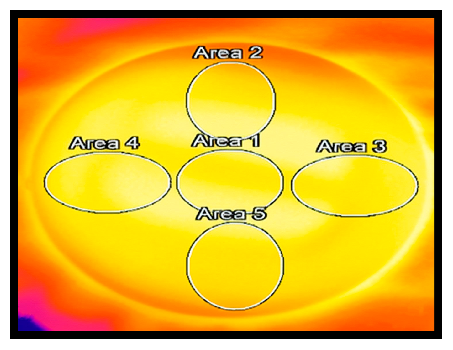
The thermal camera data were processed offline using the camera and MATLAB software. Each thermal image of an implant was evenly divided into five geometric regions representing the anatomical breast subunits: (i) center; (ii) superior; (iii) inferior; (iv) lateral; and (v) medial (Figure 2). The camera software was used to (i) convert the image to grayscale, (ii) calculate the mean temperature for each region, and (iii) generate cooling graphs. Entropy, skewness, and kurtosis were computed using MATLAB functions for each region.

2.1.4. Statistical Analysis

A one-way ANOVA was conducted to compare temperature changes across the three silicone-gel implants (Implant 1: 350 cc, Implant 2: 300 cc, and Implant 3: 280 cc) at each time point (baseline, post-heating, and 40 min post-cooling). Post hoc Tukey tests were performed to identify significant differences between implant pairs (p < 0.05). Temperatures at baseline and 40 min post-cooling were compared using a paired t-test. Statistical analyses were performed using Stata SE 16, and significance was set at the standard 5% level.

2.2. Numeric Model Simulation

To complement the in situ thermal imaging experiments, a numerical model was created to simulate heat transfer in breast tissue. It compared a standard anatomical model with one that included a silicone-gel implant. This approach used the Finite Element Method (FEM) in SOLIDWORKS (version 2018, Dassault Systèmes, Vélizy-Villacoublay, France) to generate geometry and COMSOL Multiphysics® (version 5.5, COMSOL Inc., Burlington, MA, USA) for detailed heat transfer analysis under controlled boundary conditions.

2.2.1. SolidWorks Model

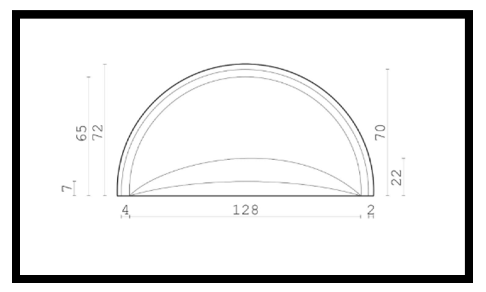
The breast geometrical model consists of 4 main tissue layers, namely (from outermost to innermost), cutaneous, adipose, glandular, and muscular. The dimensions of the model are shown in Figure 3. The silicone-gel implant model features a glandular layer replaced with a silicone-gel implant, thereby simulating a prepectoral implant-based breast reconstruction. The geometric models of the breast were created using SOLIDWORKS software and subsequently integrated into COMSOL software for heat transfer simulations and analyses.

2.2.2. COMSOL Numerical Simulations

The assumptions of the numeric model were as follows: (i) steady-state conditions; (ii) no radiation; (iii) constancy of parameters (k, h, ρ.); (iv) the materials of the different breast layers are homogeneous and isotropic; (v) the temperature distribution of the boundary conditions is uniform; and (vi) environmental conditions, such as atmospheric pressure and gravity, do not affect the model.
The FEM is widely used for solving engineering and mathematical problems [24]. It is frequently applied in areas like structural analysis and heat transfer [25]. FEM is a numerical technique specifically designed to solve partial differential equations involving two or three spatial variables, commonly referred to as boundary value problems. To solve a problem, the FEM divides a large system into smaller parts called ‘finite elements.’ This division is achieved through spatial discretization, which involves creating a mesh of the object. This mesh represents the numerical domain for the solution and comprises a finite number of points. The FEM representation of a boundary value problem ultimately results in a system of algebraic equations [26]. The method approximates the unknown function over the domain. The simple equations for these finite elements are then combined into a larger system of equations that models the entire problem. FEM uses variational methods from calculus of variations to approximate a solution by minimizing an associated error function. In our case, we used COMSOL software (COMSOL Inc., Burlington, MA, USA) to solve the finite element equations of the current numerical model simulation.

2.2.3. Heat Transfer Simulation

Typically, heat transfer occurs through four primary mechanisms: conduction, convection, phase change, and radiation. Conduction is the process through which heat diffuses through a solid or a liquid. Convection is the transfer of heat due to the bulk movement of molecules within gases and liquids. Phase change is the process by which matter changes from one form to another due to changes in temperature. Radiation is the process by which heat is transferred through electromagnetic radiation; the current COMSOL simulation, however, incorporates heat transfer by conduction. The general equation for heat transfer by conduction is presented in Equation (1), where q, k, A, and dT/dx represent the heat, thermal conductivity, the cross-sectional area, and the temperature gradient, respectively. The current numeric model utilized this equation to simulate heat transfer in the studied silicone-gel model.
Heat transfer by conduction:
q = k A d T d x
Heat transfer in the human body is defined by Equation (2), where ρ b , c b , ω b , T b ρ b , c b , ω b , T b and k represent blood density, specific heat of blood, blood perfusion rate, arterial temperature, and thermal conductivity, respectively. The current numeric model utilizes this equation to simulate heat transfer through human tissue layers.
Heat transfer in the human body
ρ n c n T x = k n 2 T + ρ b c b ω b T b T n + Q n
Table 1 summarizes the heat transfer parameters in the four breast tissue layers simulated in the numeric model, namely (from outermost to innermost), skin, fat, gland, and muscle.
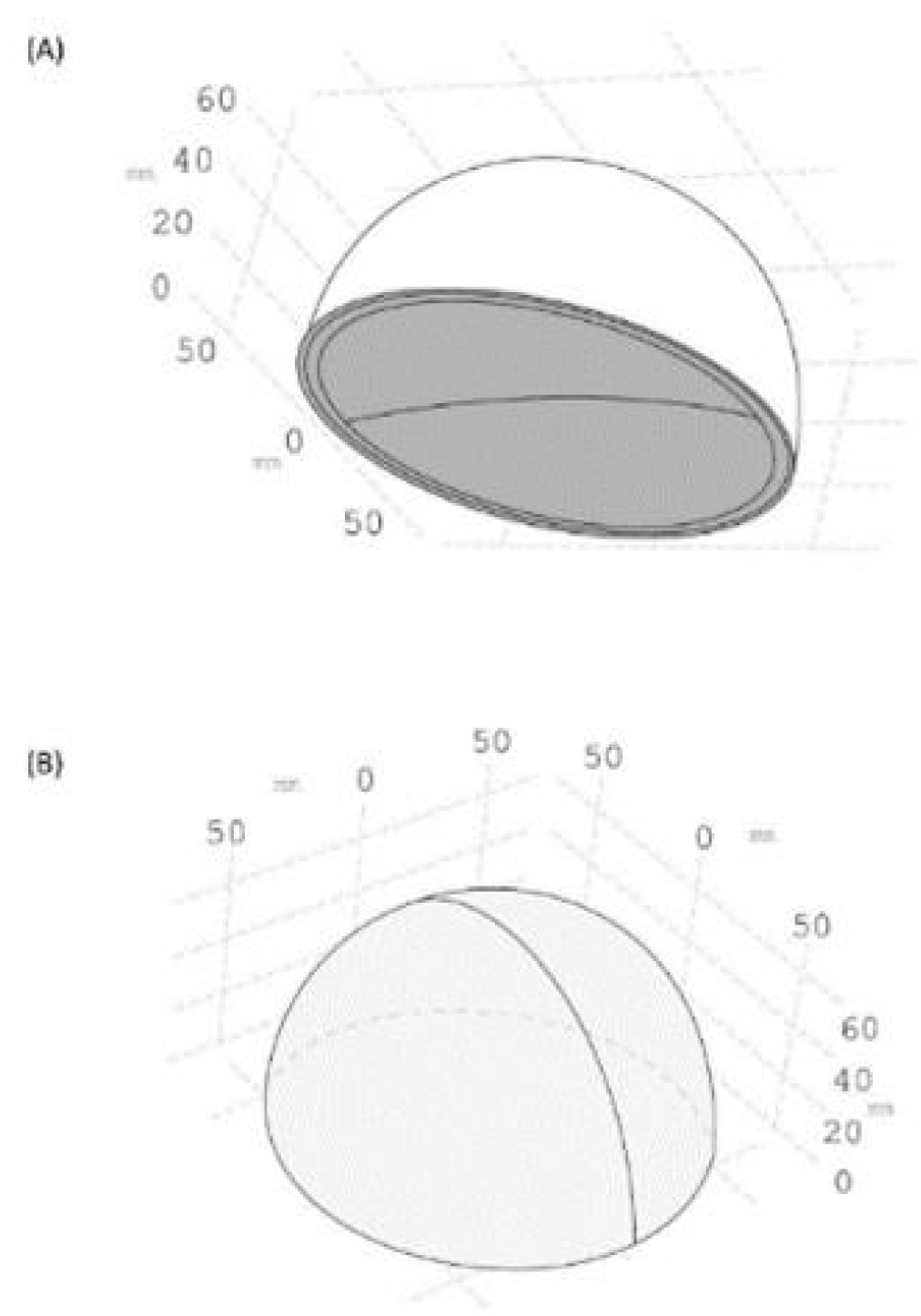
Regarding boundary conditions, the temperature at the bottom of the model was set to 37 °C, simulating the body’s internal temperature (Figure 4A). The temperature on the outer surface of the skin was set to 40 °C to simulate external heating of the skin (Figure 4B). The skin surface convective boundary condition is depicted by Equation (3), where h = 10 W/K m 2 , m 2 ,  k = 0.235 W/Km, and T = T0 = 21 °C.
Skin surface convective boundary condition
k T η = h T 0 T

3. Results

3.1. In Situ Experiment Baseline Silicone-Gel Implant Temperature Change

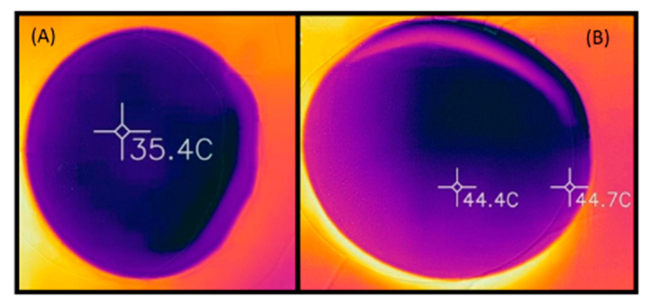
Before initiating the in situ experiment, we determined the time it took for the implant to reach 45 °C under exposure to sunlight. The initial temperature of the implant was 35.4 °C, reaching 44.4 °C within an hour (Figure 5A,B).

3.2. Thermal Images

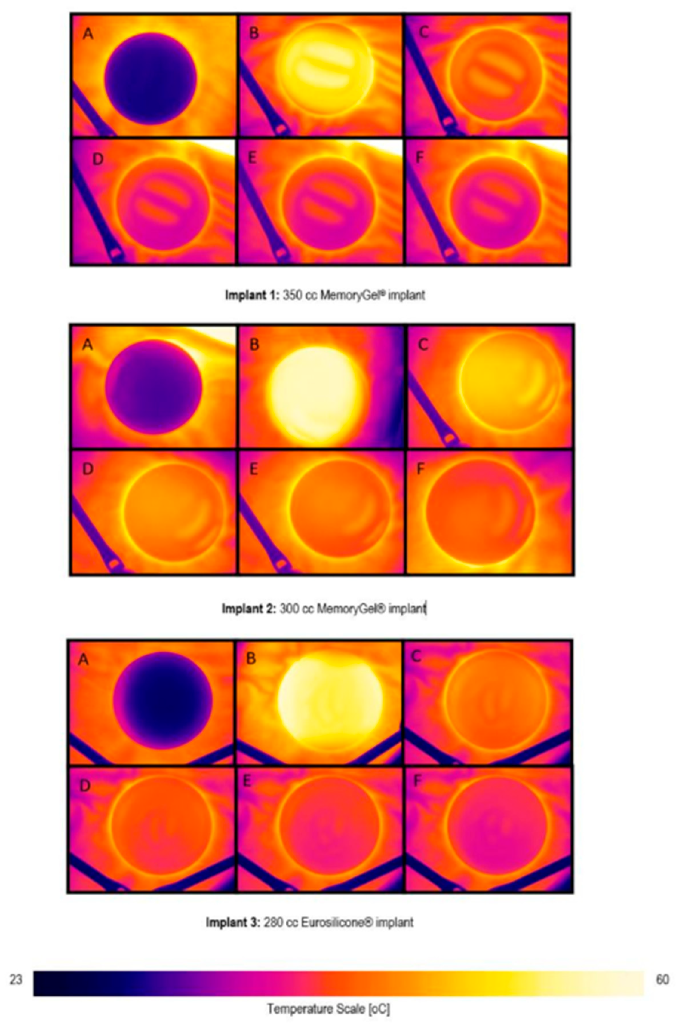
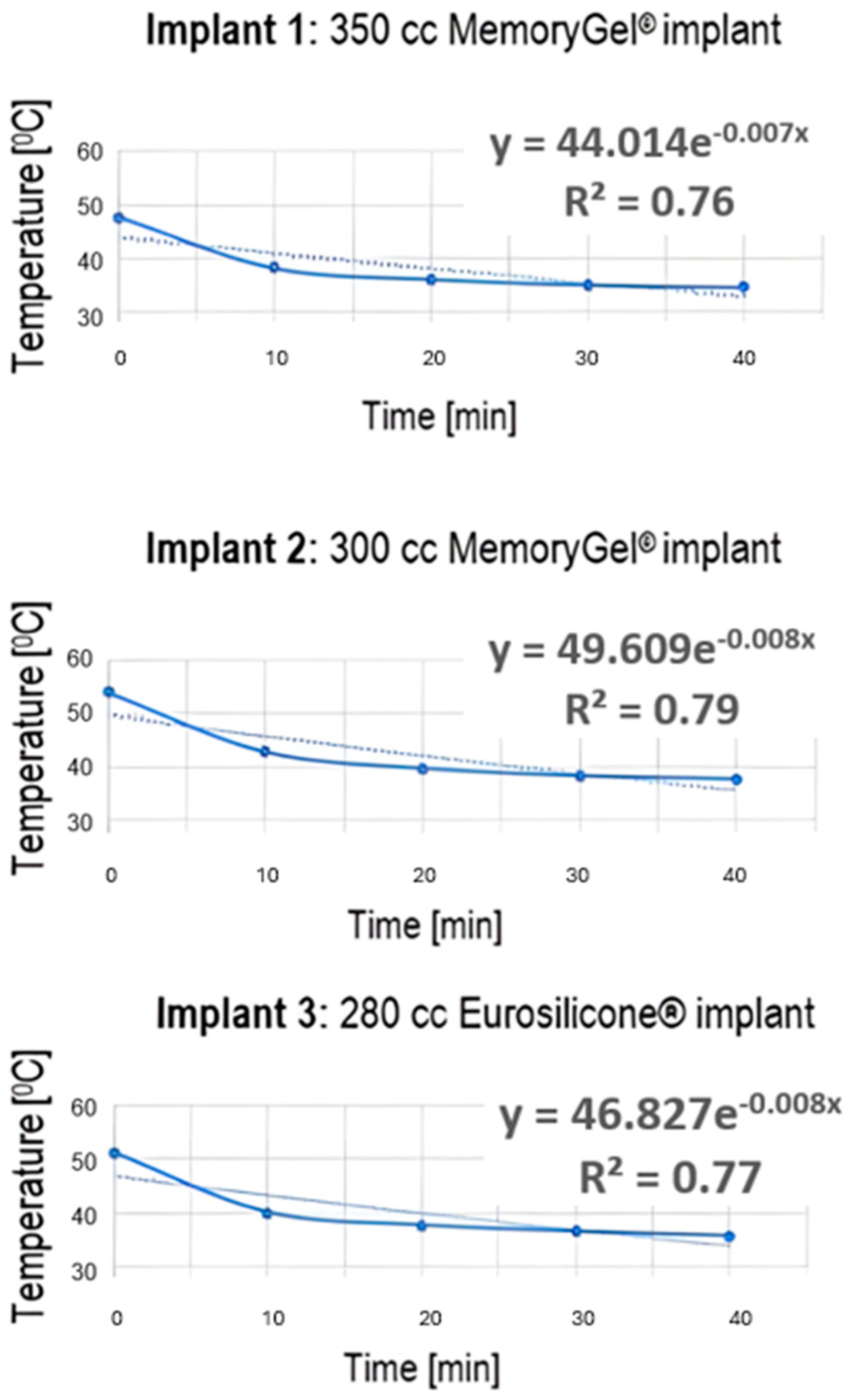
The first and second phases of the in situ experiment involved heating silicone-gel implants using a hot water bottle. Figure 6 shows the thermal images of the silicone-gel implants during the experiments. Figure 7 provides a quantitative breakdown of the temperature changes in the implants depicted in Figure 6. The images were taken at room temperature before external heating, right after exposure to external heating, and at 10, 20, 30, and 40 min after the external heating was removed.
The thermal images indicate the temperature of an area by its color. The brighter the area, the higher the temperature in it as compared to its surroundings. In keeping with this, the darker the area, the lower the temperature in that area is compared to its surroundings. Figure 6 illustrates this thermodynamic feature; the silicone-gel implants in thermal image A of each figure are the darkest, indicating that they have the lowest temperature. On the contrary, the silicone-gel implants in thermal image B of each figure are the brightest, indicating that they have the highest temperature. Lastly, images C, D, E, and F visualize the implants gradually becoming less bright, corresponding to the implants cooling over time. Notably, each implant has a slight defect, evident in the thermal images.

3.3. Temperature Data Extracted from Thermal Images

Table 2 summarizes the characteristics of three silicone-gel implants: Implant 1 (350 cc), Implant 2 (300 cc), and Implant 3 (280 cc). The average baseline temperatures of these implants ranged from 26.14 °C to 27.98 °C before external heating was applied. A one-way ANOVA revealed a significant effect of implant volume on baseline temperature, with F(2, 12) = 15.67 and p < 0.001 (ω2 = 0.66). As a result, comparisons for post-heating and measurements taken 40 min post-cooling were made using relative values expressed as percentage changes, calculated with the following formula:
Percentage Change = ((New Value − Old Value)/Old Value) × 100.
A one-way ANOVA was conducted to compare the mean percentage change in post-heating temperatures among three types of silicone-gel implants. The analysis indicated a significant effect of implant type on the percentage change in temperature (F(2, 12) = 11.767, p = 0.001). The effect size was large (ω2 = 0.589), indicating that the implants exhibited distinct thermal responses after being externally heated. Post hoc Tukey tests confirmed significant differences in several pairwise comparisons. Specifically, Implant 2 was significantly warmer than Implant 1, with a mean difference of −10.330% (t = −4.657, p = 0.001). Similarly, Implant 3 was also significantly warmer than Implant 1, showing a mean difference of −7.772% (t = −3.504, p = 0.011). The standard error was consistent at 2.218. A p-value adjustment was applied for multiple comparisons. The comparison between Implant 2 and Implant 3 revealed a mean difference of 2.558% (t = 1.153, p = 0.502), indicating that while the smaller implants (300 cc and 280 cc) accumulated a similar amount of heat, they retained more heat than the larger 350 cc implant.
The ANOVA results also indicated a significant effect of implant volume on percentage change in temperature after a 40 min cooling period (F(2, 12) = 5.569, p = 0.019, ω2 = 0.383), demonstrating distinct thermal properties during cooling. Post hoc Tukey tests revealed significant differences in several pairwise comparisons: Implant 1 compared to Implant 2 showed a mean difference of 3.112% (t = 2.296, p = 0.028), while Implant 1 compared to Implant 3 showed a mean difference of 2.932% (t = 2.283, p = 0.038). The comparison between Implant 2 and Implant 3 revealed a mean difference of −0.180% (t = −1.173, p = 0.984). The p-values were adjusted for multiple comparisons, with significant differences observed between Implants 1 and 2, as well as between Implants 2 and 3; however, no significant difference was found between Implants 1 and 3.
Despite these decreases, all three implants maintained temperatures above their respective baseline levels (Student’s t-test, p < 0.001).
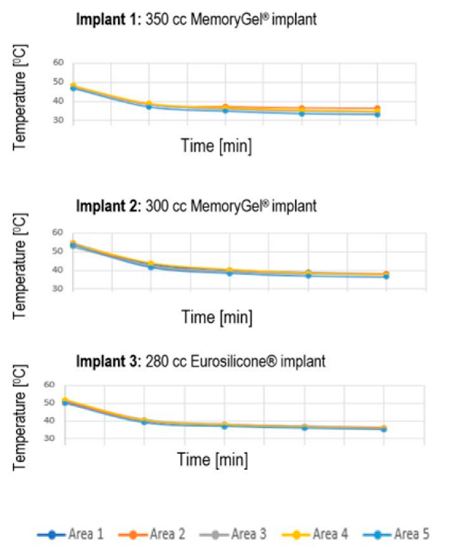
Figure 8 summarizes the mean cooling process temperatures for each area of the silicone-gel implants. Notably, the highest temperature was obtained immediately upon removing the external heating, and it remained greater than 30 °C in all cases, which was still higher than the initial temperatures listed in Table 2.

3.4. Numeric Model

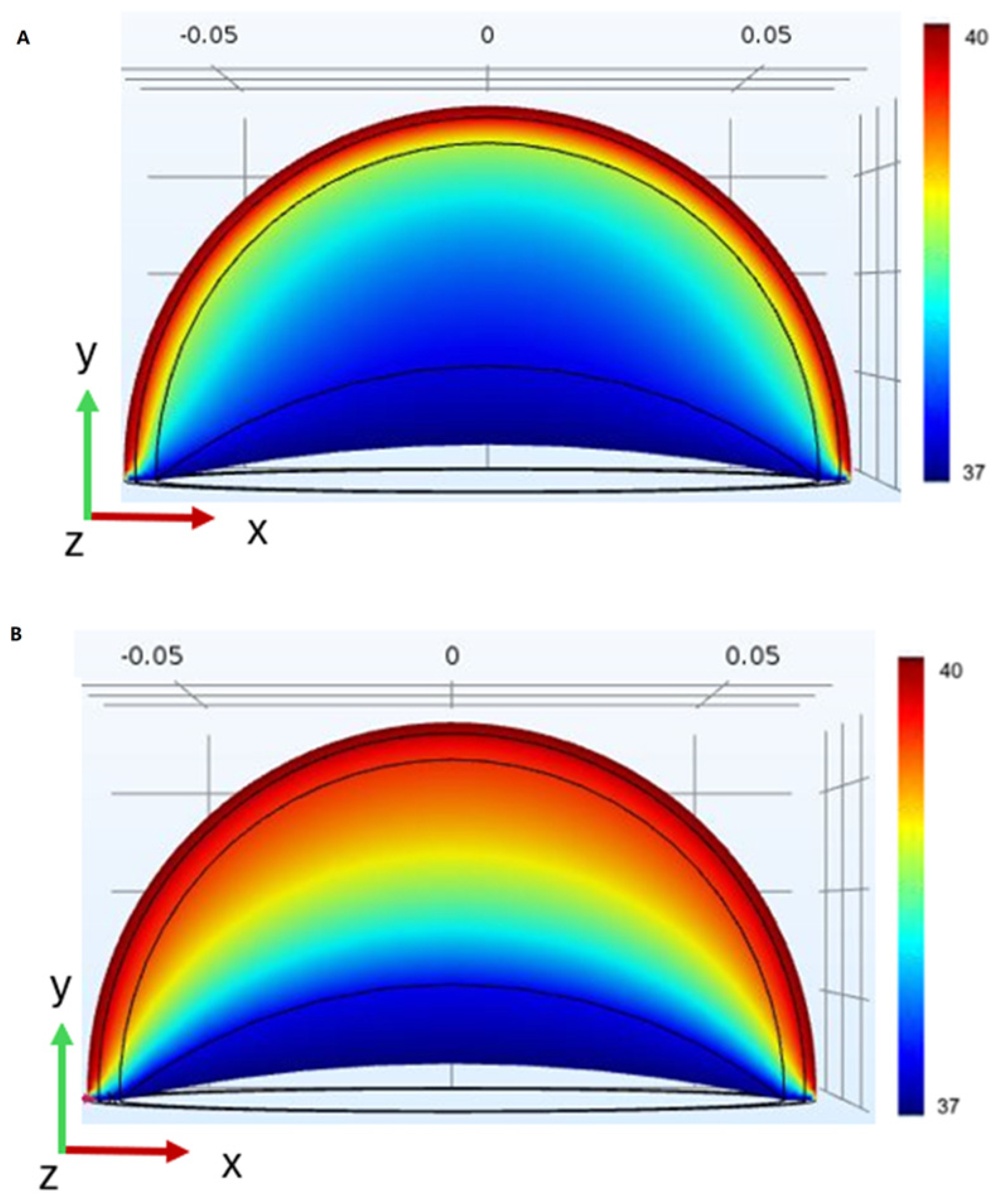
Figure 9A illustrates the temperature distribution at the X-Y plane throughout the four main tissue layers of a breast, namely (outermost to innermost), cutaneous, adipose, glandular, and muscular. Figure 9B illustrates the silicone-gel implant model, where the glandular layer has been replaced with the silicone-gel implant, thereby simulating a prepectoral implant-based breast reconstruction (full coverage with the muscle is not always possible). Comparing the models illustrates that in the modified (latter) model, high temperatures spread toward the innermost muscle layer significantly more robustly than in the original model.

3.5. Summary of Experimental and Simulated Data Findings

Table 3 presents a comparison between the experimental in situ thermal imaging data and the Finite Element Method (FEM) simulation results for silicone-gel breast implants subjected to external heating. The experimental data from three implants (350 cc, 300 cc, and 280 cc) indicated baseline temperatures ranging from 26.14 °C to 27.98 °C. After heating, temperatures increased to between 47.68 °C and 53.92 °C, representing an increase of 82.41% to 92.74%. After 40 min of cooling, the temperatures returned to between 34.70 °C and 37.56 °C, reflecting a decrease of 27.22% to 30.34%. These findings indicate significant heat retention (refer to Table 2).
In contrast, the FEM simulations, which utilized a prepectoral implant model with internal and external boundary conditions of 37 °C and 40 °C, respectively, demonstrated greater thermal penetration within the implant model compared to a standard breast model. However, the exact post-cooling temperatures were not measured due to the steady-state assumptions used in the simulations (see Figure 9).
Both methods confirm that silicone-gel implants retain heat for a longer period than native tissue. The experimental data highlight the specific thermal responses of the implants, while the simulations reveal deeper heat penetration, underscoring the potential risks of thermal injury.

4. Discussion

The current study aimed to utilize an in situ experiment based on thermal imaging and numerical model simulation to quantitatively and qualitatively delineate the effect of external heating on silicone breast implants. Several noticeable findings emerged from the current study. Our findings are consistent with recent thermo-mechanical modeling approaches in implantable medical devices, where FEM using representative volume element techniques has shown value in predicting temperature-induced stress and heat distribution in sensitive anatomical regions [27]. While previous studies, such as the study by Brandon et al. [28], have focused on the mechanical and thermal degradation thresholds of breast implant materials under extreme conditions, our study addresses a distinct clinical concern, namely, the thermal dynamics of silicone-gel implants under moderate external heat exposure as encountered in real-world settings. Future studies may benefit from integrating both mechanical and thermal performance data to further enhance safety assessment. The distinct thermal responses observed among the silicone-gel implants (350 cc, 300 cc, and 280 cc) are attributable to their varying sizes and associated physical properties, particularly their surface-to-volume ratios. The significant influence of implant volume on post-heating temperatures, as well as during the cooling phase, suggests that smaller implants are more adept at accumulating and dissipating heat. This is likely due to their higher surface-to-volume ratio, which facilitates more efficient heat absorption relative to their mass during external heating, resulting in a greater percentage temperature increase for the 300 cc and 280 cc implants compared to the 350 cc implant. During the 40 min cooling period, the smaller implants also exhibit enhanced heat dissipation, as indicated by significant differences in percentage change, reflecting a more rapid release of heat due to their higher surface-to-volume ratio [29]. These results highlight how implant size influences thermal dynamics, making smaller implants more susceptible to heat accumulation. This holds significant clinical relevance, as it may increase the risk of thermal injuries in patients with smaller silicone-gel implants, particularly those with reduced sensation post-mastectomy. Therefore, customized patient education and monitoring strategies, such as handheld thermal imaging cameras for smartphones, are essential. This is further supported by the observation that all implants maintained temperatures significantly above their baseline levels even after 40 min of cooling.
The numerical model of the silicone-gel implants demonstrated a more robust spread of increased temperatures toward the innermost muscle layer than the original model of a breast without an implant. These differences in heat conduction stem from the diverse thermodynamic properties of native human tissues versus silicone-gel breast implants. Notably, the risk of breast burns in patients with implants often stems more from patient behavior and sensory loss than from the implants themselves. After a mastectomy, many patients experience reduced sensation in the chest area, resulting in decreased awareness of heat exposure, such as from prolonged sun exposure. This highlights the need for patient education about the risks of heat exposure and the importance of protective measures, particularly for those with compromised skin sensation.
Additionally, blood vessels and blood flow, which are present in native human tissues, are lacking in silicone-gel implants. These components comprise the homeostatic system of the body, which contributes to heat convection from the body to the environment. Specifically, upon external heating, the body reacts physiologically with vasodilation, i.e., the body physiologically reacts with vasodilation, resulting from the relaxation of smooth muscle cells within the blood vessel walls, particularly in the large veins, arteries, and arterioles [30]. This reaction promotes the cooling of blood due to a greater distribution capacity, i.e., its flow through a larger surface area. This physiological reaction, which is of paramount importance in situations of tissue overheating, is lacking in silicone-gel implants, and this could be the main reason for the difference between the original human tissue model and the silicone-gel implant model.
Several limitations within this work are to be acknowledged. The in situ experiment and numerical model provide initial insights into how silicone-gel breast implants behave under external heating. The temperature of the implants decreased by approximately 30% over a 40 min period after initial heating. However, it remained above the baseline temperature, suggesting that the implants tend to retain heat. This heat retention may be worsened by defects identified through thermal imaging, as presented in our previous study [23]. However, these findings are specific to the prepectoral implant model and controlled conditions, which limit direct application to clinical scenarios.
Additionally, the numerical model shows that heat penetrates the implant more deeply than native tissue, suggesting a potential risk of thermal injury. This needs to be validated in vivo, considering patient-specific factors such as skin thickness, sensory loss, and blood perfusion. The absence of physiological responses, such as vasodilation in the implants, may also contribute to heat retention, but further research is necessary to quantify this effect in clinical settings. It is crucial to educate patients about the risks of prolonged heat exposure, especially for those who have reduced sensation following a mastectomy.
The native tissues that remain postoperatively may vary depending on the vicinity of the excised tumor to their margins, age, skin quality, BMI, vascular comorbidities, preoperative radiation and chemotherapy, as well as a history of pregnancies, breastfeeding, weight loss, and smoking [31]. Notably, these factors were not included in the current study, which primarily aimed to evaluate the direct effect of external heating on silicone-gel implants rather than its amalgamated effect evoked in combination with the factors above.

5. Conclusions

Thermal imaging is an effective method for characterizing the thermal profiles of silicone-gel breast implants, particularly in terms of their response to external heating. The numerical model suggests that external heating has a significant impact on silicone-gel implants, potentially causing heat-induced injury to native tissues and compromising the implant’s integrity. However, it is important to note that these findings are preliminary and based solely on in situ studies. Future research should validate these findings, taking into account patient-specific factors and various reconstruction techniques. While thermal imaging shows promise as a non-invasive tool for assessing implant integrity, its clinical utility still requires further investigation through controlled trials. The added potential for safe and user-friendly home monitoring could enhance its practical application for patients.

Author Contributions

Conceptualization, O.H., J.H. and Z.O.-B.; data curation, O.H., J.H., Y.B., B.K. and Z.O.-B.; formal analysis, O.H., J.H., R.-R.N., Y.B., B.K., O.G., E.B. and Z.O.-B.; investigation, O.H., J.H., Y.B., B.K., O.G. and Z.O.-B.; methodology, O.H., J.H., Y.B., B.K., O.G. and Z.O.-B.; project administration, O.H., J.H. and Z.O.-B.; resources, O.H., J.H. and Z.O.-B.; software, O.H., J.H. and Z.O.-B.; supervision, O.H., J.H. and Z.O.-B.; validation, O.H., J.H., R.-R.N., Y.B., B.K., O.G., M.C., R.K., E.B. and Z.O.-B.; visualization, O.H., J.H., R.-R.N., Y.B., B.K., O.G., M.C., R.K., E.B. and Z.O.-B.; writing—original draft, O.H., J.H., R.-R.N., Y.B., B.K., O.G. and Z.O.-B.; writing—review and editing, O.H., J.H., R.-R.N., Y.B., B.K., O.G., M.C., R.K., E.B. and Z.O.-B. All authors have read and agreed to the published version of the manuscript.

Funding

The author(s) received no financial support for the research, authorship, and/or publication of this article.

Institutional Review Board Statement

Not applicable.

Informed Consent Statement

Not applicable.

Data Availability Statement

The original contributions presented in this study are included in the article. Further inquiries can be directed to the corresponding author.

Conflicts of Interest

The authors declare no conflicts of interest.

References

  1. Gil-Olarte, P.; Gil-Olarte, M.A.; Gómez-Molinero, R.; Guil, R. Psychosocial and sexual well-being in breast cancer survivors undergoing immediate breast reconstruction: The mediating role of breast satisfaction. Eur. J. Cancer Care 2022, 31, e13686. [Google Scholar] [CrossRef]
  2. Martins Faria, B.; Martins Rodrigues, I.; Verri Marquez, L.; da Silva Pires, U.; Vilges de Oliveira, S. The impact of mastectomy on body image and sexuality in women with breast cancer: A systematic review. Psicooncología 2021, 18, 91–115. [Google Scholar] [CrossRef]
  3. Meshkin, D.H.; Firriolo, J.M.; Karp, N.S.; Salibian, A.A. Management of complications following implant-based breast reconstruction: A narrative review. Ann. Transl. Med. 2023, 11, 416. [Google Scholar] [CrossRef]
  4. Jimenez, R.B.; Packowski, K.; Horick, N.; Rosado, N.; Chinta, S.; Koh, D.; Sobti, N.; Specht, M.; Liao, E.C. The timing of acute and late complications following mastectomy and implant-based reconstruction. Ann. Surg. 2023, 278, e203–e208. [Google Scholar] [CrossRef]
  5. Blok, Y.L.; van Lierop, E.; Plat, V.D.; Corion, L.U.M.; Verduijn, P.S.; Krekel, N.M.A. Implant loss and associated risk factors following implant-based breast reconstructions. Plast. Reconstr. Surg. Glob. Open 2021, 9, e3708. [Google Scholar] [CrossRef]
  6. Fischer, J.P.; Wes, A.M.; Tuggle, C.T., III; Serletti, J.M.; Wu, L.C. Risk analysis of early implant loss after immediate breast reconstruction: A review of 14,585 patients. J. Am. Coll. Surg. 2013, 217, 983–990. [Google Scholar] [CrossRef] [PubMed]
  7. Yuen, J.C.; Coleman, C.A.; Erickson, S.W. Obesity-related risk factors in implant-based breast reconstruction using alloderm. Plast. Reconstr. Surg. Glob. Open 2017, 5, e1231. [Google Scholar] [CrossRef] [PubMed]
  8. Laporta, R.; Longo, B.; Sorotos, M.; Farcomeni, A.; Patti, C.; Mastrangeli, M.R.; Rubino, C.; di Pompeo, F.S. Breast reconstruction following nipple-sparing mastectomy: Clinical outcomes and risk factors related complications. J. Plast. Surg. Hand Surg. 2017, 51, 427–435. [Google Scholar] [CrossRef] [PubMed]
  9. Mak, J.C.; Kwong, A. Complications in post-mastectomy immediate breast reconstruction: A ten-year analysis of outcomes. Clin. Breast Cancer 2020, 20, 402–407. [Google Scholar] [CrossRef]
  10. Friedrich, M.; Krämer, S.; Friedrich, D.; Kraft, C.; Maass, N.; Rogmans, C. Difficulties of breast reconstruction–problems that no one likes to face. Anticancer Res. 2021, 41, 5365–5375. [Google Scholar] [CrossRef]
  11. Osman, F.; Saleh, F.; Jackson, T.D.; Corrigan, M.A.; Cil, T. Increased postoperative complications in bilateral mastectomy patients compared to unilateral mastectomy: An analysis of the NSQIP database. Ann. Surg. Oncol. 2013, 20, 3212–3217. [Google Scholar] [CrossRef] [PubMed]
  12. Chattha, A.; Bucknor, A.; Kamali, P.; Van Veldhuisen, C.L.; Flecha-Hirsch, R.; Sharma, R.; Tobias, A.M.; Lee, B.T.; Lin, S.J. Comparison of risk factors and complications in patients by stratified mastectomy weight: An institutional review of 1041 consecutive cases. J. Surg. Oncol. 2017, 116, 811–818. [Google Scholar] [CrossRef] [PubMed]
  13. Bennett, K.G.; Qi, J.; Kim, H.M.; Hamill, J.B.; Pusic, A.L.; Wilkins, E.G. Comparison of 2-Year complication rates among common techniques for postmastectomy breast reconstruction. JAMA Surg. 2018, 153, 901–908. [Google Scholar] [CrossRef]
  14. MacDonald-Nethercott, M.; Malata, C.M.; Irwin, M.S.; Benyon, S.L.; Wong, K.Y. Analysis of complications following implant-based breast reconstruction in breast cancer patients. Eur. J. Plast. Surg. 2023, 46, 1059–1068. [Google Scholar] [CrossRef]
  15. Alhindi, N.; Bamakhrama, B.; Alzahrani, A.; Mortada, H.; Ali, N.M.; Alruwaili, A.; Baamir, N.; Aljaaly, H. Risk factors of implant loss and complications post-implant based breast reconstruction: A meta-analysis. Eur. J. Plast. Surg. 2023, 46, 865–874. [Google Scholar] [CrossRef]
  16. Nickel, K.B.; Fox, I.K.; Margenthaler, J.A.; Wallace, A.E.; Fraser, V.J.; Olsen, M.A. Effect of noninfectious wound complications after mastectomy on subsequent surgical procedures and early implant loss. J. Am. Coll. Surg. 2016, 222, 844–852. [Google Scholar] [CrossRef] [PubMed]
  17. Olsen, M.A.; Nickel, K.B.; Fox, I.K.; Margenthaler, J.A.; Wallace, A.E.; Fraser, V.J. Comparison of wound complications after immediate, delayed, and secondary breast reconstruction procedures. JAMA Surg. 2017, 152, e172338. [Google Scholar] [CrossRef] [PubMed]
  18. Jaeger, M.; Wagman, Y.; Liran, A.; Harats, M.; Winkler, E.; Haik, J.; Tessone, A. A literature review of burns in reconstructed breasts after mastectomy. Wounds 2016, 28, 422–428. [Google Scholar]
  19. Delfino, S.; Brunetti, B.; Toto, V.; Persichetti, P. Burn after breast reconstruction. Burns 2008, 34, 873–877. [Google Scholar] [CrossRef]
  20. Brzezinski, R.Y.; Levin-Kotler, L.; Rabin, N.; Ovadia-Blechman, Z.; Zimmer, Y.; Sternfeld, A.; Finchelman, J.M.; Unis, R.; Lewis, N.; Tepper-Shaihov, O.; et al. Automated thermal imaging for the detection of fatty liver disease. Sci. Rep. 2020, 10, 15532. [Google Scholar] [CrossRef]
  21. Ovadia-Blechman, Z.; Hoffer, O.; Halak, M.; Adrai, K.; Zimmer, Y.; Silverberg, D.; Rabin, N. Assessment of blood distribution in response to post-surgical steal syndrome: A novel technique based on Thermo-Anatomical Segmentation. J. Biomech. 2021, 119, 110304. [Google Scholar] [CrossRef]
  22. Peko Cohen, L.; Ovadia-Blechman, Z.; Hoffer, O.; Gefen, A. Dressings cut to shape alleviate facial tissue loads while using an oxygen mask. Int. Wound J. 2019, 16, 813–826. [Google Scholar] [CrossRef] [PubMed]
  23. Hoffer, O.; Haik, J.; Nir, R.R.; Beck, Y.; Kofler, B.; Heyman, E.; Golan, O.; Ovadia-Blechman, Z. Effect of External Heating on Silicone Gel Breast Implants: Can Heat Exposure Precipitate Burns and Implant-Related Complications? Plast. Reconstr. Surg. 2023, 151, 529e–530e. [Google Scholar] [CrossRef]
  24. Erhunmwun, I.; Ikponmwosa, U. Review on finite element method. J. Appl. Sci. Environ. Manag. 2017, 21, 999–1002. [Google Scholar] [CrossRef]
  25. Sharma, R.; Jadon, V.K.; Singh, B. A review on the finite element methods for heat conduction in functionally graded materials. J. Inst. Eng. (India) Ser. C 2015, 96, 73–81. [Google Scholar] [CrossRef]
  26. Surana, K.S.; Reddy, J.N. The Finite Element Method for Boundary Value Problems: Mathematics and Computations; CRC Press: Boca Raton, FL, USA, 2016. [Google Scholar]
  27. Lone, A.A.; Sheikh, N.A.; Butt, M.M. Coupled thermo-mechanical finite element analysis of cranial implants using micromechanical representative volume element approach. J. Inst. Eng. India C 2024, 105, 483–494. [Google Scholar] [CrossRef]
  28. Brandon, H.J.; Nichter, L.S.; Back, D.D. New evaluation procedure for multi-dimensional mechanical strains and tangent moduli of breast implants: IDEAL IMPLANT® structured breast implant compared to silicone gel implants. Bioengineering 2019, 6, 43. [Google Scholar] [CrossRef] [PubMed]
  29. Árpád, I.W.; Kiss, J.T.; Kocsis, D. Role of the volume-specific surface area in heat transfer objects: A critical thinking-based investigation of Newton’s law of cooling. Int. J. Heat. Mass. Transf. 2024, 227, 125535. [Google Scholar] [CrossRef]
  30. Cramer, M.N.; Gagnon, D.; Laitano, O.; Crandall, C.G. Human temperature regulation under heat stress in health, disease, and injury. Physiol. Rev. 2022, 102, 1907–1989. [Google Scholar] [CrossRef]
  31. Córdoba, E.E.; Lacunza, E.; Güerci, A.M. Clinical factors affecting the determination of radiotherapy-induced skin toxicity in breast cancer. Radiat. Oncol. J. 2021, 39, 315–323. [Google Scholar] [CrossRef]
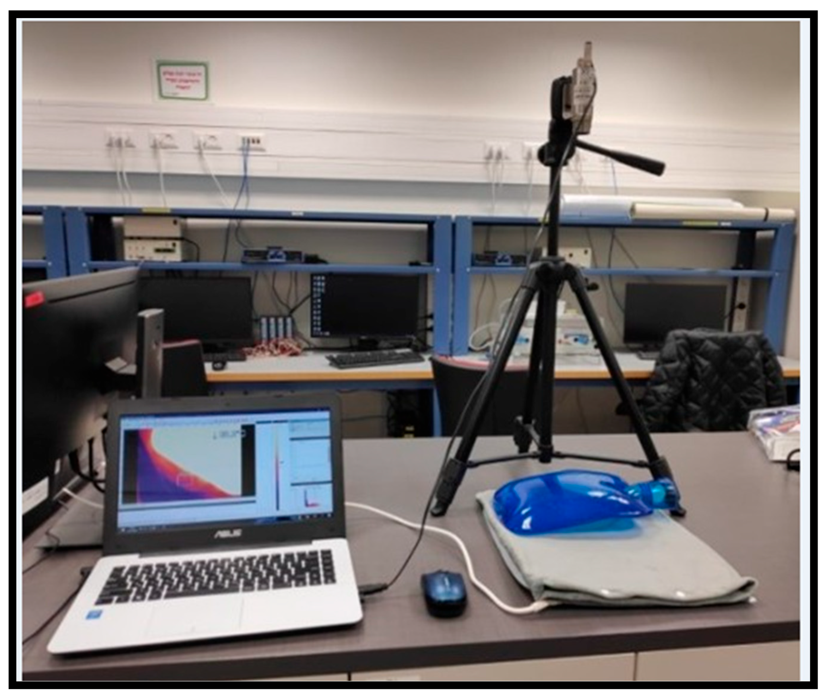
Figure 1. The Optris Xi 400 thermal camera setup. By connecting to a computer, detailed filming and precise monitoring of the implant’s thermal response during experiments can be achieved.
Applsci 15 08831 g001
Figure 2. The five regions of each implant. Each thermal image of an implant was divided into five sections representing the breast’s anatomical subunits (Area 1–5).
Applsci 15 08831 g002
Figure 3. The dimensions of the breast silicone-gel implant geometric model (mm). Depicted are the cross sections of the four main layers, namely (outermost to innermost), skin, fat, gland, and muscle.
Applsci 15 08831 g003
Figure 4. Three-dimensional model of the breast: outer surface view (A) and bottom view (B) as used in the COMSOL heat transfer simulation.
Applsci 15 08831 g004
Figure 5. Baseline examination of the silicone-gel implants’ time to heat from baseline (A) to a temperature simulating sun exposure (B).
Applsci 15 08831 g005
Figure 6. Thermal images were taken of silicone-gel implants during different stages: at room temperature before exposure to external heating using a hot water bottle (A); immediately after exposure to external heating (B); and 10, 20, 30, and 40 min after the removal of external heating (C,D,E,F, respectively).
Applsci 15 08831 g006
Figure 7. The cooling process of the silicone-gel implants after exposure to a hot water bottle.
Applsci 15 08831 g007
Figure 8. Mean cooling process temperatures of all of the areas after exposure to the hot water bottle.
Applsci 15 08831 g008
Figure 9. Model (A) illustrates the temperature distribution at the X-Y plane throughout the four main tissue layers of a breast, namely (outermost to innermost), cutaneous, adipose, glandular, and muscular. Model (B) depicts the silicone-gel implant model, where the glandular layer has been replaced with the silicone-gel implant, thereby simulating a prepectoral implant-based breast reconstruction. The color bar on the right indicates temperature levels in degrees Celsius.
Applsci 15 08831 g009
Table 1. The heat transfer properties of the different breast layers.
Skin §FatGlandMuscleSilicone
ρ     k g m 3 1200930105011001050
C p J k g K 3396.32770377038001500
k     W m K 0.3750.210.480.480.14
w b 1 s 0.0005----
§ The average of the skin’s sub-layers; ρ : blood density; C p : specific blood heat; k: thermal conductivity; wb: blood perfusion rate.
Table 2. Application of external heating to silicone-gel implants.
ImplantAreaBaseline (°C)Post-Heating (°C)40 min Post-Cooling (°C)Post-Heating (Percentage Change, %)40 min Post-Cooling
(Percentage Change, %)
1125.9048.1034.7085.71−27.86
226.4047.5036.5079.92−23.16
326.3047.8034.4081.75−28.03
426.2048.2034.8083.97−27.80
525.9046.8033.1080.69−29.27
Mean (SD)26.14 (0.23)47.68 (0.56)34.70 (1.21)82.41 (2.39)−27.22 (2.35)
2127.5054.5038.2098.18−29.91
228.2054.6038.1093.62−30.22
327.8052.7037.6089.57−28.65
428.6054.2037.5089.51−30.81
527.8053.6036.4092.81−32.09
Mean (SD)27.98 (0.43)53.92 (0.79)37.56 (0.72)92.74 (3.57)−30.34 (1.26)
3126.0050.9035.5095.77−30.26
226.6050.7036.2090.60−28.60
326.8051.6035.9092.54−30.43
428.1052.0035.7085.05−31.35
526.8050.1035.0086.94−30.14
Mean (SD)26.86 (0.77)51.06 (0.75)35.66 (0.45)90.18 (4.30)−30.16 (0.99)
Notes: The percentage change for post-heating values is based on the baseline values, while the percentage change for values measured 40 min post-cooling is based on the post-heating values; Implant 1 (350 cc), Implant 2 (300 cc), and Implant 3 (280 cc). The abbreviation “SD” stands for standard deviation.
Table 3. Comparison summary of experimental in situ data and simulated data for silicone-gel breast implants.
MetricExperimental Data (In Situ)Simulated Data (FEM)Comparison Notes
Baseline Temperature (°C)26.14–27.98 (average across implants: 350 cc: 26.14, 300 cc: 27.98, 280 cc: 26.86; Table 2)37 °C (bottom boundary condition, simulating body temperature; Section 2.2.3)The simulated baseline assumes a higher, uniform body temperature; experimental data reflect actual lab conditions (25 °C).
Post-Heating Temperature (°C)47.68–53.92 (average across implants: 350 cc: 47.68, 300 cc: 53.92, 280 cc: 51.06; Table 2)40 °C (external skin surface boundary condition; Section 2.2.3)Experimental temperatures are higher due to direct heating (65 °C hot water bottle); simulated data use a lower external temperature.
40 Min Post-Cooling Temperature (°C)34.70–37.56 (average across implants: 350 cc: 34.70, 300 cc: 37.56, 280 cc: 35.66; Table 2)Not quantified; implied retention above baseline (Figure 9, Section 3.4)Experimental data show significant heat retention; simulation suggests prolonged retention but lacks specific values.
Post-Heating % Change82.41–92.74% (350 cc: 82.41%, 300 cc: 92.74%, 280 cc: 90.18%; Table 2)Not quantified; qualitative increase due to implant’s thermal properties (Section 3.4)Experimental data show a significant temperature rise; simulation confirms higher heat accumulation in the implant model.
40 Min Post-Cooling % Change−27.22 to −30.34% (350 cc: −27.22%, 300 cc: −30.34%, 280 cc: −30.15%; Table 2)Not quantified; implies slower cooling in implant model (Figure 9, Section 3.4)Experimental data indicate partial cooling; simulation suggests slower heat dissipation due to a lack of perfusion.
Thermal Penetration/RetentionHeat retention above baseline after 40 min (Section 3.3)Deeper thermal penetration in the implant model vs. the standard breast model (Figure 9, Section 3.4)Both methods confirm that implants retain heat longer than native tissue, with simulations showing deeper penetration.
Notes: Experimental data were obtained from thermal imaging of three silicone-gel implants (350 cc, 300 cc, and 280 cc) heated using a 65 °C hot water bottle (Section 2.1.2); Simulated data were generated using COMSOL FEM with a prepectoral implant model, assuming homogeneous layers and no perfusion (Section 2.2.2); Differences in temperature values indicate the use of experimental (lab-based, variable heating) versus simulated (controlled boundary conditions) methodologies; The simulation does not provide precise post-cooling temperatures because it relies on steady-state assumptions, which limit the ability to make direct numerical comparisons.
Disclaimer/Publisher’s Note: The statements, opinions and data contained in all publications are solely those of the individual author(s) and contributor(s) and not of MDPI and/or the editor(s). MDPI and/or the editor(s) disclaim responsibility for any injury to people or property resulting from any ideas, methods, instructions or products referred to in the content.