1. Introduction
Winter wheat is one of the most important cereal crops in Lithuania, both economically and in terms of cultivated area. Between 2015 and 2024, the harvested area of winter wheat increased from 708,300 to 879,709 hectares, with average yields from 4.75 to 5.31 tons per hectare [
1]. These trends reflect advances in crop management and rising demand. However, they also place greater importance on minimizing losses during mechanical harvesting, where a significant portion of yield can still be lost due to inefficient threshing and separation processes [
2].
One of the effective ways to reduce losses is by optimizing the operation of combine harvesters. Key factors include equipment type, operating parameters, and harvest timing [
3]. In recent years, types of equipment for longitudinal axial flow, such as combine harvesters, have become more common in Lithuania and other European countries. Their share of the national fleet has grown from 12% in 2015 to 35% in 2023 [
4]. These machines use a rotor-based threshing and separation system consisting of a rotor, a concave, and a top cover with internal helical guide vanes. Grain is separated from straw through a combination of impact, rubbing, and centrifugal force as the material moves along the rotor [
5].
Material flow speed through the system is regulated by four key adjustments: rotor speed, concave clearance, rotor configuration, and guide vane inclination. While rotor speed and concave settings have been extensively studied, guide vane inclination has gained increased attention for its strong effect on performance. Guide vanes help direct the crop axially through the rotor housing. Smaller vane angles slow the crop down, increasing residence time and improving separation, but potentially increasing grain damage. Larger angles accelerate crop flow, reducing damage but raising the risk of unseparated grain loss.
Several studies have confirmed the importance of guide vane inclination. Chuan-Udom et al. [
6] observed that rotor speed, guide vane angle, feed rate, and grain moisture all significantly influenced grain losses. In a related study, they reported that guide vane inclination accounted for 40.66% of threshing losses [
7]. Doungpueng and Chuan-Udom [
8] showed that different vane inclination patterns affected both energy use and separation losses, although they had little effect on grain breakage. Saeng-ong et al. [
9] reported that increasing vane inclination in a corn shelling unit reduced losses, but also led to a linear increase in power consumption.
Despite evidence, most harvesters still use fixed guide vane settings, particularly in the threshing area. This can become a major limitation in field conditions, where the feed rate and biomass vary throughout the field. In high-yielding European wheat fields, high biomass volumes are common, which puts additional load on the rotor system. Variability in crop density, lodging, and moisture leads to uneven feeding and inconsistent threshing–separation performance [
10,
11]. This can reduce grain quality and increase loss rates [
12,
13,
14].
To improve performance under these variable conditions, several researchers have proposed real-time adjustment systems for rotor and separation parameters [
15,
16,
17,
18]. However, the focus has mostly been on the separation section, with few studies addressing adaptive control of the threshing zone. Tang et al. [
19] suggested that variable-mass threshing conditions require more responsive designs, but practical implementations remain rare. Guide vane inclination is now recognized as a key variable. It has greater influence than feed rate on loss and impurity rates and is second only to rotor speed in its effect on grain damage [
20,
21]. Adjusting the vanes dynamically—especially in both the threshing and separation areas—could therefore offer major performance benefits. Harrison [
22] and others have shown that vane angle changes material movement and system load, which directly affects separation efficiency and power consumption.
Most prior research on guide vane systems has focused on simulations or bench-scale testing under controlled conditions. In contrast, this study implements and validates a fully synchronized guide vane control system directly under real-world field conditions.
To address this gap, this study investigates an axial-flow combine harvester equipped with eight internal guide vanes. In the original factory configuration, the first two vanes (located in the threshing section) are fixed, while the remaining six (in the separation section) are adjustable. As a result, material movement is only controlled in the latter part of the rotor housing. This configuration is not ideal in high-yielding conditions where crop density is high throughout the system [
5,
10]. The main objective of this research was to improve performance by redesigning the system so that all eight guide vanes could be adjusted simultaneously. A mechanical linkage was developed to couple the vane adjustments in both the threshing and separation zones. The integrated system was implemented on a combine harvester and tested under real field conditions. Its performance was compared with an identical combine operating in the same field, under the same crop and environmental conditions. By evaluating the new system, this study aims to determine whether synchronized guide vane control can reduce grain losses, improve separation efficiency, lower fuel consumption, and better adapt to variable biomass in winter wheat harvesting.
2. Materials and Methods
The analysis consists of two stages: evaluating the guide vanes on the threshing–separation unit in winter wheat, and evaluating the modified guide vanes of the threshing–separation unit top cover with 8 variable guide vanes. The main monitored parameters were threshing, separation loss, performance, and fuel consumption.
2.1. Theoretical Estimation of Material Flow
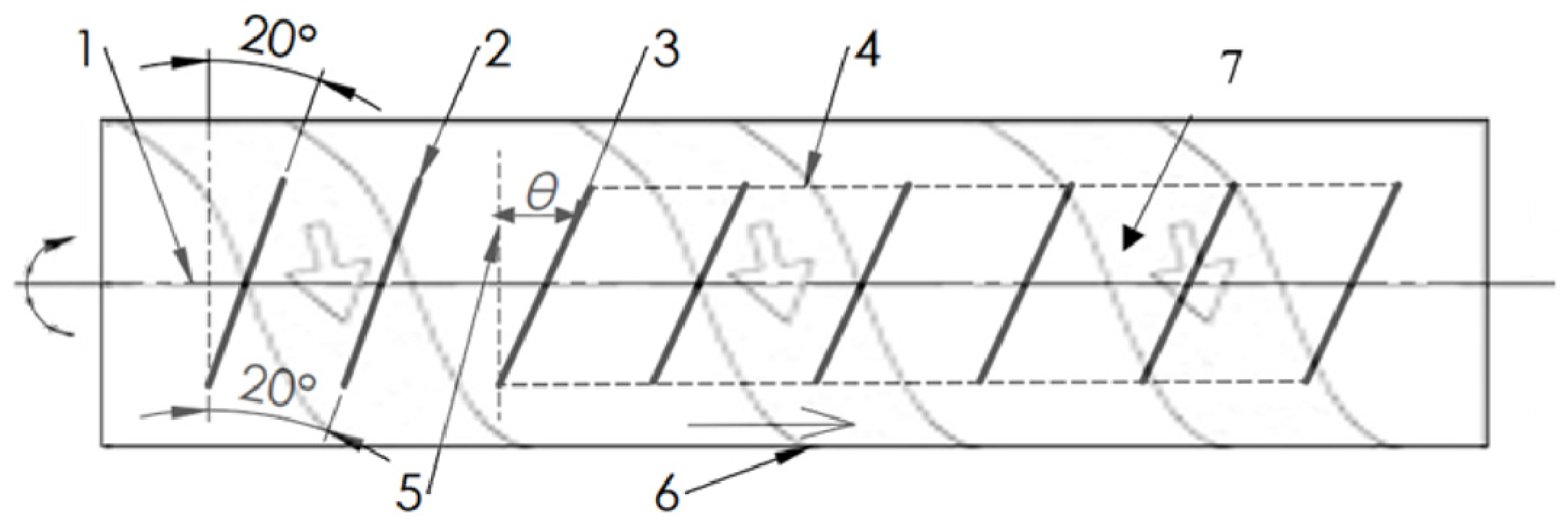
The selected study object is a combine harvester with one axial threshing–separation apparatus, which consists of a transition cone with bolted helical vane (1), a feeding head with two pitch impellers (2), a rotor upper cover with adjustable guide vanes (3), and rotor with rasbars (4) (
Figure 1).
Material in an axial rotor does not move in a straight line—it spirals due to rotor rotation and the internal guide vane effect. The guide vane with a certain angle controls the axial crop movement speed. The crop movement speed can be accelerated by increasing the guide vane angle and decreasing it to a smaller angle. The guide vane can be adjusted accordingly by the feed rate when it increases, also increasing the guide vane angle to accelerate crops through the threshing–separation unit (
Figure 2). The poor design of the guide vanes could lead to poor threshing performance, resulting in crop accumulation, broken grain rate, and rotor blockage [
23].
One of the key indicators for characterizing this flow is the material rotation number, the number of helical revolutions the material completes around the rotor axis during its passage. The mathematical modeling approach for predicting the material rotation number and axial velocity based on the nonlinear kinematic theory was developed by Miu and Kutzbach [
18,
24]. This method more accurately represents the physical behavior of crop material in axial-flow threshing units compared to classical helical path assumptions [
18,
23,
24].
In Miu’s nonlinear kinematic model, the rotation angle
of the material and its longitudinal position
along the rotor are related through [
24]:
where:
—scaling constant (depending on guide vane angle and crop properties),
—exponent reflecting slippage (usually
),
—effective radius of the material trajectory,
—material position along the rotor length, R—radius of the rotor,
—weighted average clearance between the rotor and the concave.
The number of material revolutions completed from entry to position
x is [
24]:
This function captures the non-uniform, gradually increasing rotational behavior of the material due to slippage and varying axial resistance.
To link the combine’s adjustable vane angle (
) to the model, empirical constants
and
were assigned based on prior research. Larger vane angles tend to push material more aggressively (lower
) and reduce slippage (higher
) [
24].
In addition to modeling rotation, Miu’s nonlinear kinematic model provides the actual speed of crop material as it moves through the axial rotor. The material follows a curved path, and its total speed is influenced by both axial movement and rotational swirl [
18,
23,
24].
The tangential velocity of the material is given by [
24]:
where
—tangential (swirling) speed m s
−1,
—axial speed of the material m s
−1,
—empirical constants, and
—material distance from the inlet m.
The absolute velocity of the material along its curved path is then:
To ensure dimensional consistency, the constant carries units of m1−b, and the full expression gives a result in m s−1.
A higher implies a shorter threshing–separation time, less exposure to rasp bars, and lower torque load on the rotor. Lower means materials are threshing–separating longer, more time for separation, but risk of overloading or even plugging the rotor.
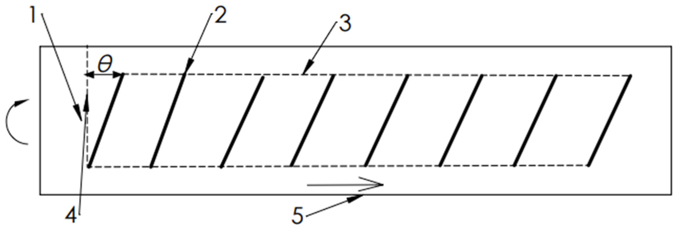
In total, the study object has 8 guide vanes, where 2 front guide vanes are in fixed positions at 20°, and the last 6 vanes are variable in inclination from 10–35° by 5° steps (
Figure 2). This adjustment can be made by the operator from inside the cabin. To understand theoretically how the rear vane inclination affects material movement, the two scenarios (A and B,
Table 1) were calculated.
The comparison demonstrates that Scenario A favors separation and exposure but risks rotor overloading, while Scenario B enhances flow and reduces load but may underperform in separating dense material. Critically, the fixed 20° front vanes limit adaptive control across the rotor length, leading to flow mismatches that impair uniform material handling. A system with fully adjustable vanes would enable smoother axial progression and better optimization for varying crop conditions.
2.2. Modified Top Cover with 8 Linked Guide Vanes
To improve flow regulation and adaptability of the axial threshing–separation system under varying crop conditions, the factory rotor top cover—equipped with only six adjustable guide vanes and two fixed front vanes—was redesigned (
Figure 3). The modified guide vane assembly allows all eight guide vanes to be linked and adjusted simultaneously via a mechanical synchronization system. This design change is intended to eliminate discontinuities in material flow, reducing internal resistance zones and ensuring consistent crop handling throughout the entire length of the rotor housing.
The standard configuration of the combine harvester includes:
Two fixed guide vanes at the front section (positions 0.2 m and 0.4 m), set at a constant angle of 20°.
Six adjustable guide vanes at the rear (positions 0.6 m to 1.6 m), controlled by an electric actuator integrated with the combine system.
This partial adjustability leads to a flow mismatch along the rotor, especially under high-yield, high-MOG (material other than grain) conditions. Specifically, when rear vane angles are reduced to increase residence time for better separation, the fixed front vanes continue to accelerate crop flow. This results in an unbalanced axial progression rate, where the material accumulates in the middle rotor segments. Such accumulation can elevate rotor torque demand, increase grain damage due to over-threshing, and impair uniform separation.
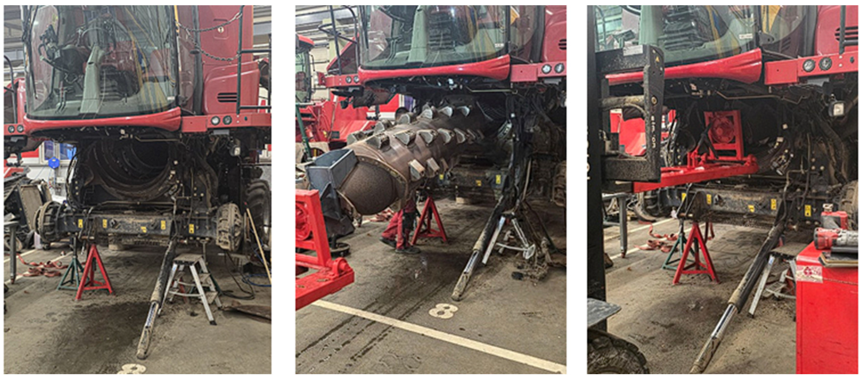
To solve this, the top cover from the combine was fully removed with guide vanes (
Figure 4).
The redesigned top cover was developed using SolidWorks 2024 Computer-Aided Design (CAD) software (Dassault Systems, Waltham, MA, USA) [
25]. This CAD drawing served as the basis for both component fabrication and installation layout.
Based on the CAD model, all needed dimensions were extracted (
Figure 5). Once validated digitally, the top cover was physically modified and built according to the drawings, ensuring tight tolerances and compatibility with the combine’s original mounting points (
Figure 6), and installed back to the combine (
Figure 7).
The modified top cover design was developed and fabricated with the following key features:
Eight mechanically linked guide vanes, covering the full range of the top cover (positions 0.2 m to 1.6 m).
Single actuator control, enabling a unified response to automated or manual vane angle adjustment commands.
Mechanical linkage system, composed of synchronized arms, pivot joints, and connection rods that transmit angular motion from the actuator to each vane.
This configuration ensures that all vanes adjust their inclination simultaneously and proportionally, regardless of position. As a result, the guide vane system now provides a consistent flow profile, minimizing the potential for abrupt transitions that disrupt material movement along the rotor helical path.
The linkage system is mounted to the top cover frame and interfaces with the internal guide vane shafts through connecting brackets (
Figure 6). This mechanical system is compatible with the existing combine mounting structure and does not interfere with grain handling or cleaning systems. Installation is accomplished without modifying the rotor shell or concave structure. During field pre-testing, the guide vane inclination angle varied from 10–35° to ensure that there is no contact between the guide vanes and rotor tips, even at maximum extension–retraction.
2.3. Experimental Methodology and Data Collection
A field study was conducted to evaluate the performance of two identical combines, but with different guide vane assemblies; the most important parameters are shown in
Table 2. Combine A was equipped with the modified rotor top cover guide vane assembly—eight guide vanes linked together. Combine B maintained the standard top cover with two fixed front vanes and six adjustable rear vanes.
Both combines were equipped with factory-installed Original Equipment Manufacturer (OEM) telemetry modems that have integrated Global Positioning System (GPS) tracking, as well as real-time monitoring of machine parameters via the Controller Area Network (CAN-bus) protocol. This setup enabled the collection of data such as fuel consumption, engine load, grain yield flow, throughput, broken grain, separation losses, and sieve losses (
Table 3). These data were linked to geographic coordinates, allowing for location-specific performance analysis throughout the field area.
Crop biometrical indices were determined for winter wheat Ada plants; the crops were harvested and weighed from five plots of 0.25 m2 of the field (reading accuracy 0.01 g). The length of the stem average was determined. The threshed grains from the ears were weighed, and their moisture content was determined to be 14%.
Determination of feed flow rate
(total biological mass entering the threshing system) was calculated using crop mass per square meter, header width, and travel speed. The average total biological mass was based on field sampling. Feed flow rate
was calculated using the formula:
where
is feed flow rate (kg s
−1),
is biological mass per square meter (kg m
−2),
working header width (m), and
is the forward speed of the combine (m s
−1). The forward speed
was not held constant, allowing the travel speed to vary based on guide vane angle and crop resistance. Actual forward speeds were recorded using GPS and CAN telemetry and used in the formula.
To evaluate the fuel efficiency of the combine under different guide vane configurations, fuel consumption was analyzed not only in absolute terms (liters per hour) but also as a function of productivity. The fuel consumption per ton of harvested grain was calculated using the following formula:
where
is fuel consumption (L t
−1),
—fuel consumption rate (L h
−1) monitored by telemetry, and
P—throughput (t h
−1) determined from yield monitor data.
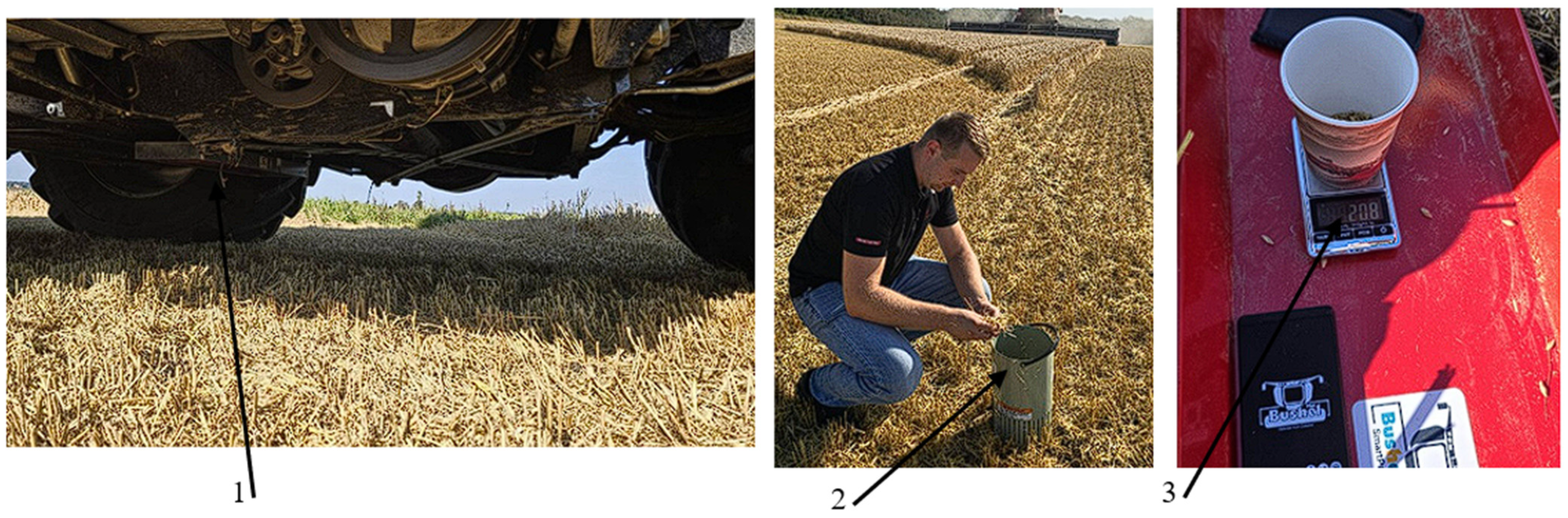
Grain losses were determined, and loss sensors were readjusted prior to the experiment. To determine grain losses, the “BushelPlus SmartPan (Bushel Plus Ltd., Brandon, MB, Canada)” system was used. This is a drop pan system that is magnetically mounted beneath the combine (
Figure 8). The pan is automatically released from the mobile application “SmartDrop (Bushel Plus Ltd., Brandon, MB, Canada)” and drops to the ground, collecting crop residue and grain falling from the combine. After the drop, the collected material is processed through the “Bushel Plus air separator”, which separates the grain from the chaff and straw. Cleaned grain is then weighed using a digital scale. Weighed grain mass, header width, and field yield are entered into the mobile application “SmartDrop”, which calculates grain loss in kg/ha or percentage from grain yield.
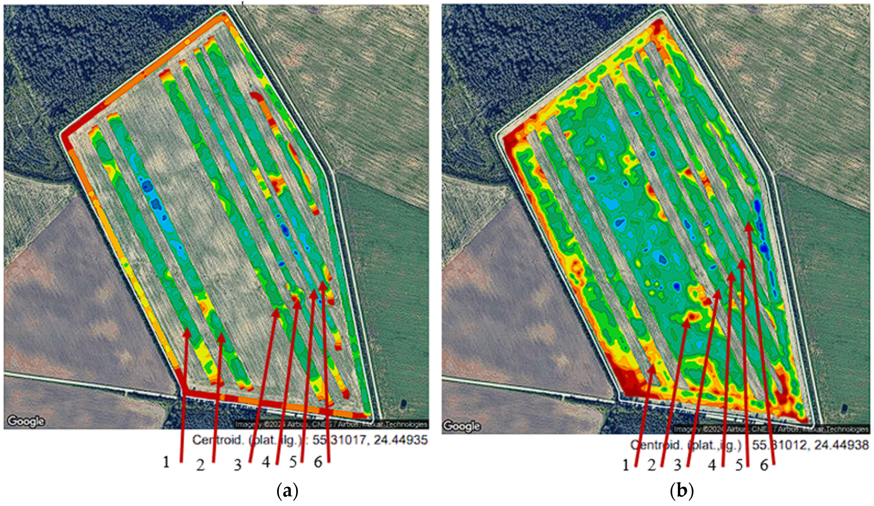
The experiment was conducted on the same day in the winter wheat field. The selected field area was 32 ha, and was divided into alternating strips harvested by Combine A and Combine B. Each strip corresponded to a different guide vane inclination setting ranging from 10–35°, as shown in
Figure 9. GPS coordinates and combine telemetry data were used to map and assign guide vane zones to specific field passes for each machine.
This experimental framework—featuring dual-machine comparisons, GPS-linked telemetry, and physical grain loss verification—enabled detailed quantification of harvesting performance under varying guide vane configurations. The collected data was analyzed to evaluate separation losses, throughput, fuel efficiency, and grain quality.
3. Results and Discussion
The performance comparison presents the outcomes of the two combine harvesters under varying guide vane inclinations. Results are grouped by key operational parameters, including separation losses, sieve losses, broken grain percentage, fuel consumption, engine load, throughput (feed flow), and productivity. Comparisons between Combine A (with the modified top cover) and Combine B (standard configuration) were made at six guide vane angles (10°, 15°, 20°, 25°, 30°, and 35°). Data were evaluated using average values from field replicates, and spatial consistency was confirmed using GPS-tagged telemetry.
3.1. Crop Biometrical Indices
The operation of combine harvesters A and B was done during the harvesting of winter wheat “Ada” on August 10, 2024, in Lithuania, Kėdainiai district. The average crop density in the experimental field was moderate, with 345 ± 53.1 stems m s
−2 (
Table 4). The total aboveground biological mass reached 841 ± 63.1 g m
−2, of which 346 ± 11.6 g m
−2 was grain mass and 249 ± 23.1 g m
−2 was straw mass. The average grain moisture content during harvest was 14%. Based on field sampling, the estimated grain yield was approximately 8.03 ± 0.27 t ha
−1.
3.2. Separation and Grain Losses
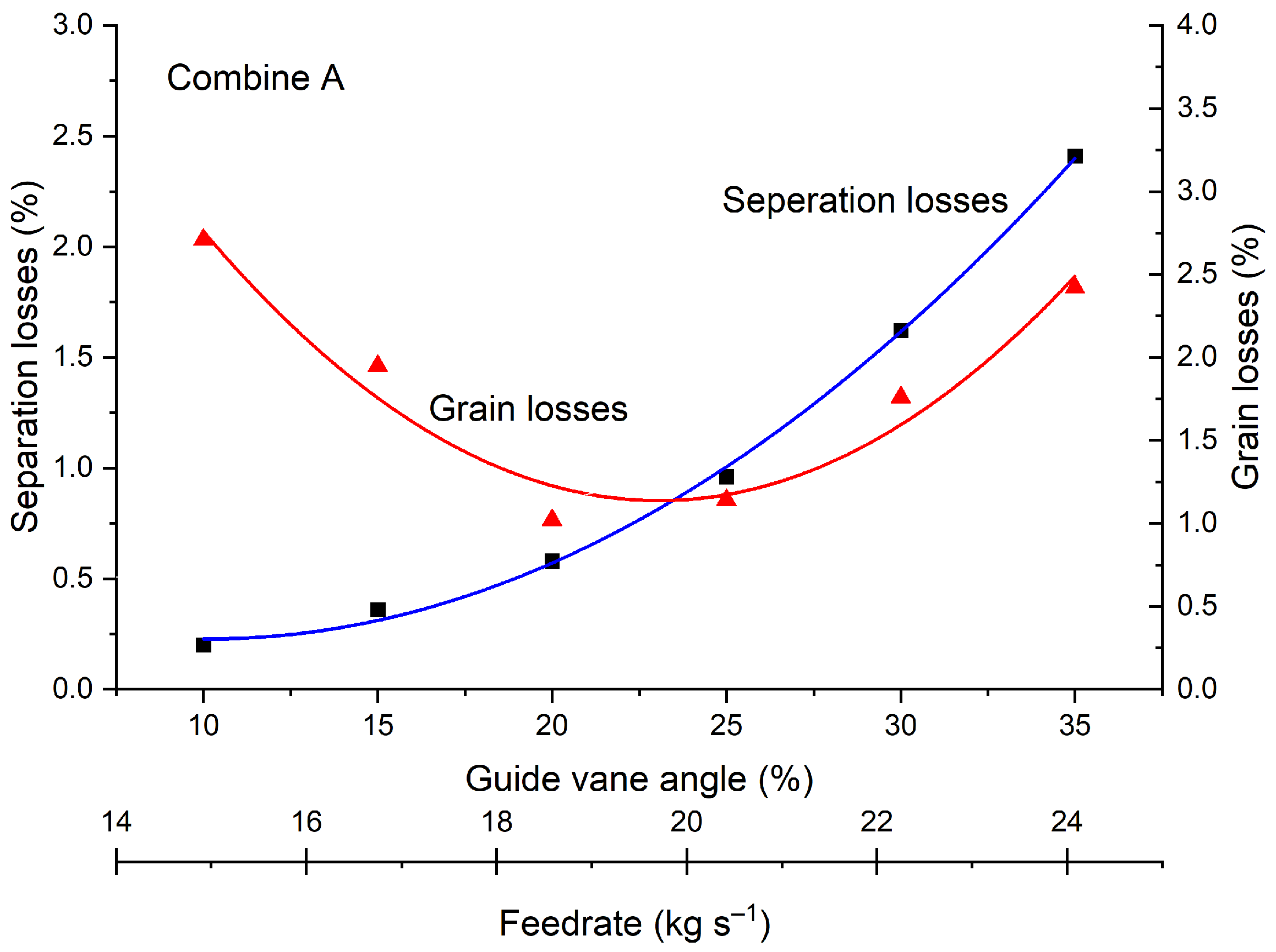
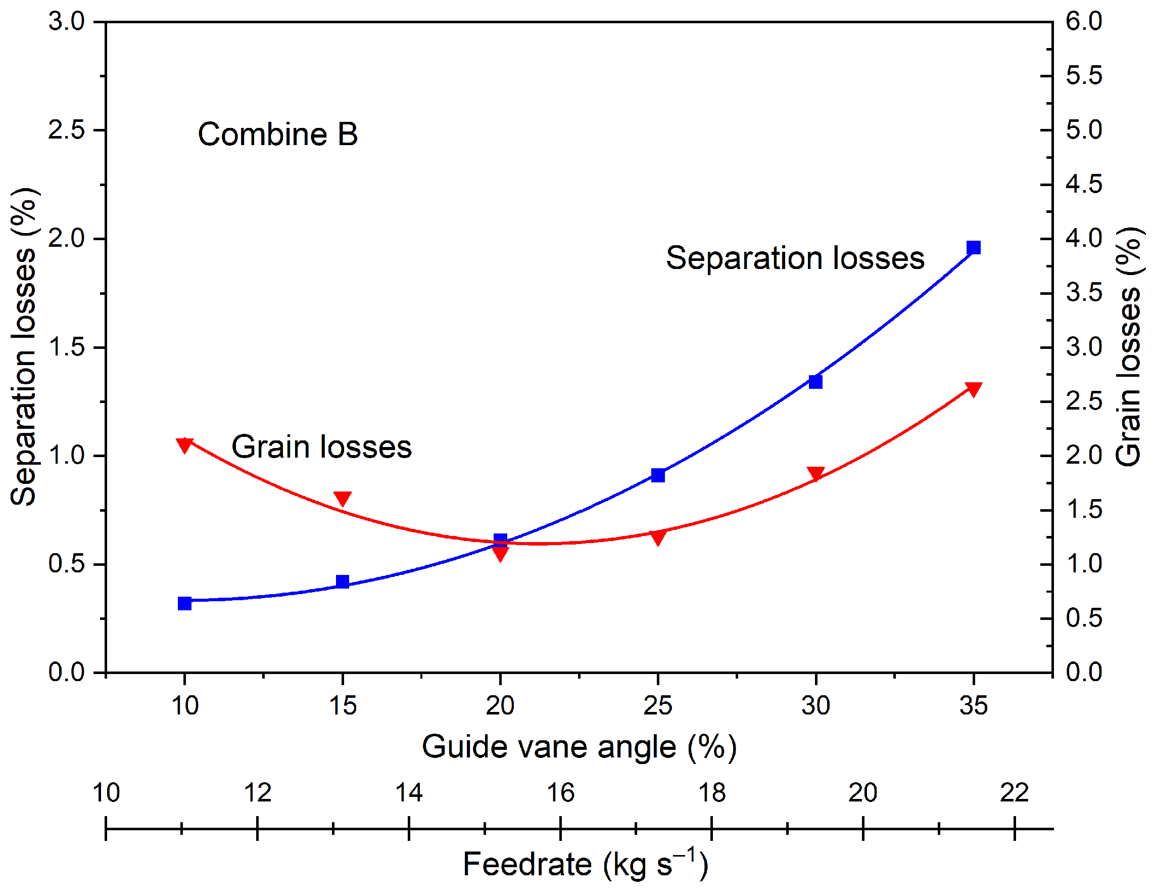
During the field test for guide vane influence on separation and grain losses, engine load was maintained at approximately 90% for both machines. Despite this, the feed flow rate varied across different guide vane settings, increasing as vane inclination was raised. This indicates that the guide vane angle regulates crop throughput and residence time within the threshing–separation unit.
Across the tested guide vane range (10–35°), Combine A exhibited more dynamic and immediate responses to changes in vane inclination. When the guide vane angle increased from 10 to 15°, separation losses in Combine A rose from 0.20% to 0.36%. In contrast, Combine B showed a more gradual change over the same interval, increasing from 0.32% to 0.42%, or 0.10 percentage points. This sharper sensitivity in Combine A reflects its fully synchronized vane adjustment, which uniformly accelerates material along the rotor housing and exposes grain to more abrupt changes in residence time. As the inclination increases, material is propelled more quickly through the threshing zone, reducing the time available for effective grain separation.
By comparison, the discontinuous design of Combine B—with fixed front vanes—creates flow mismatches between the threshing and separation sections. This limits the effective responsiveness of the system, resulting in smoother but less adaptable changes in performance. Consequently, Combine A consistently demonstrated lower separation losses than Combine B at all guide vane angles up to 35°, indicating that full-length vane control allowed more precise regulation of material flow to match separation needs (
Figure 10 and
Figure 11).
Grain losses followed a similar trend. In Combine A, total grain losses (including separation and cleaning losses) increased from 1.02% at 10° to 2.71% at 35°, while Combine B showed losses rising from 1.11% to 2.63% over the same range. The lowest grain loss in Combine A was achieved at 20°, and remained below 1.2% at 25°, whereas Combine B losses were consistently higher in this range (
Figure 10 and
Figure 11). These results suggest that optimized vane alignment in Combine A not only improved grain separation but also minimized overload at the cleaning system.
However, at higher guide vane inclinations (≥25°) both combines experienced elevated grain losses. This increase is attributed to reduced material residence time and accelerated throughput, which limits stratification and separation efficiency. When sieves overload rapidly, particularly without increased fan airflow, grain is more likely to be carried away with residue. The onset of this effect occurred more sharply in Combine A, where the fully adjustable vanes allowed greater throughput but also made the system more susceptible to separation inefficiency at high angles.
In summary, the results confirm that guide vane inclination exerts influence on separation and grain loss characteristics in axial-flow combine harvesters. While Combine A’s fully adjustable vane design enabled more responsive and effective separation at moderate angles, it also introduced higher sensitivity to changes at steep settings. Combine B, although less efficient overall, demonstrated more stable but limited adaptation. These findings emphasize the importance of synchronized material flow control in optimizing harvesting performance and minimizing grain loss.
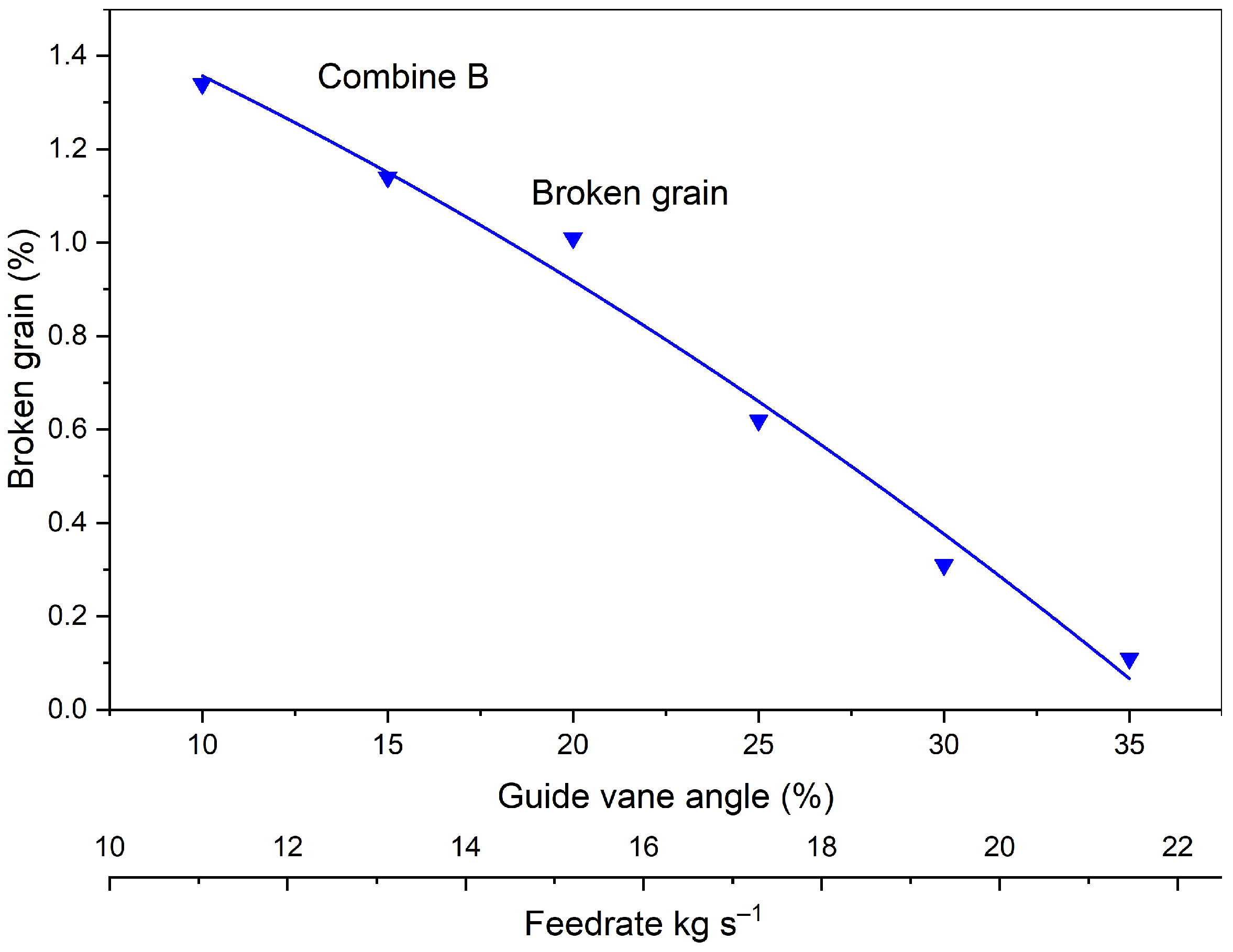
3.3. Broken Grain
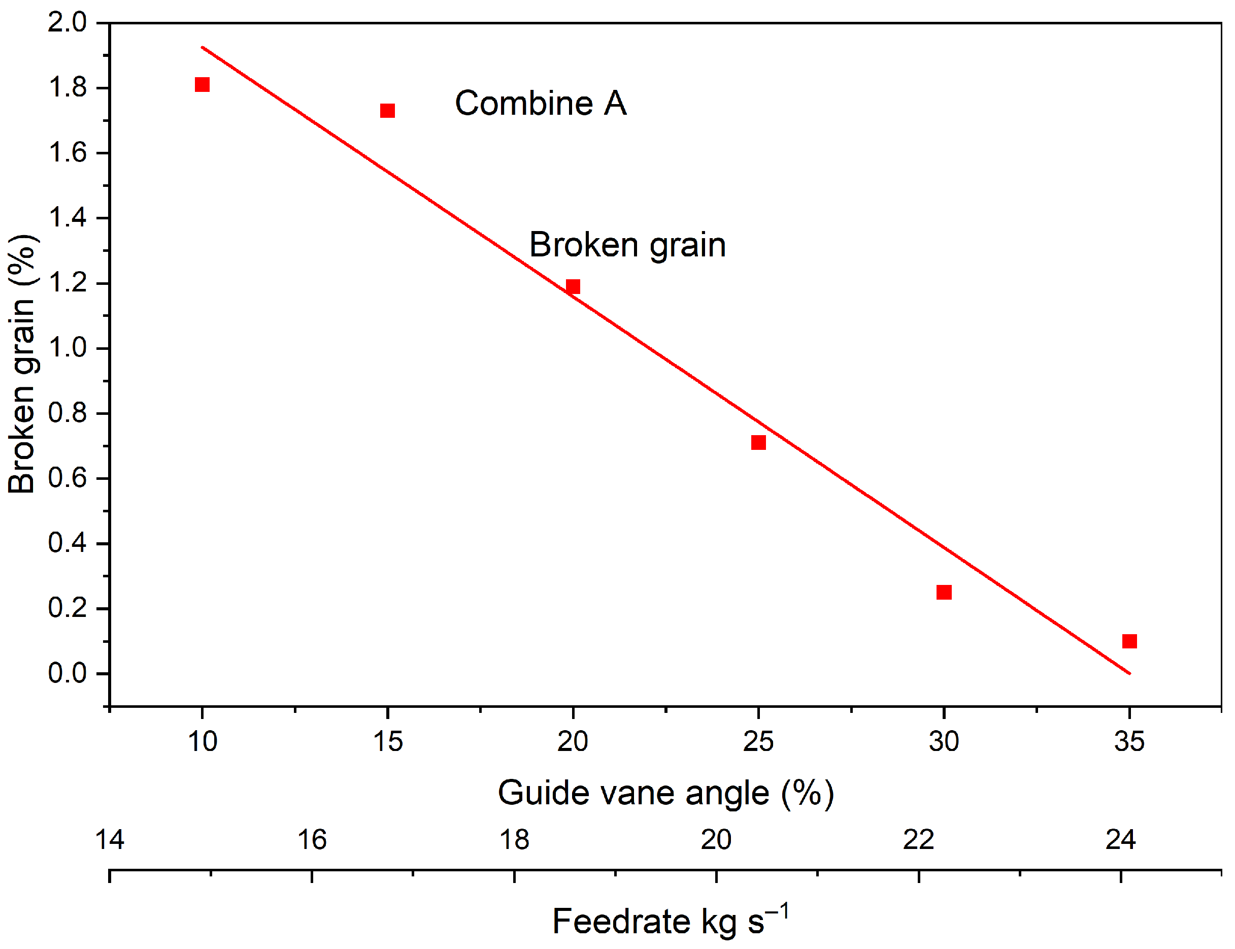
Broken grain quality indicator in combine harvester performance was directly influenced by the mechanical impact, friction, and grain residence time within the threshing system. The broken grain percentage was evaluated across a range of guide vane angles (10–35°) for Combine A and Combine B. The objective was to assess how varying the axial crop flow conditions affected grain integrity under a constant engine load of approximately 90%.
In Combine A, the broken grain percentage decreased with increasing guide vane angle at 10°; broken grain was 1.81%, but this value dropped consistently to 0.25% at 30°, and further to 0.18% at 35°.
This inverse trend suggests that higher guide vane inclination, which accelerates axial flow and reduces the number of impacts between rasp bars and grain, contributes to gentler material handling (
Figure 12 and
Figure 13). As crop material spends less time being tumbled and compressed in the threshing zone, the risk of grain cracking or fracture diminishes. The design of Combine A—with its fully adjustable vanes—allows for uniform crop acceleration and improved flow continuity, thereby minimizing areas of excessive pressure that typically result in grain breakage.
Combine B followed a similar but less pronounced trend. Broken grain decreased from 1.34% at 10° to 0.11% at 35°. Although the overall reduction is comparable to Combine A, the broken grain values at intermediate angles (e.g., 15–25°) were consistently higher in Combine B. This may be attributed to the fixed front vanes in Combine B, which can cause inconsistent material acceleration and localized buildup in the rotor. Such conditions may lead to over-threshing or uneven impact forces on the grain, especially when rear vane angles are increased but the front zone flow remains constrained.
At the optimal guide vane range of 25–30°, Combine A achieved both high productivity and low grain damage (0.71% broken grain at 25° and 0.25% at 30°). In contrast, Combine B exhibited higher broken grain at similar productivity levels—1.12% at 25° and 0.31% at 30°. These findings suggest that full-length vane control not only improves separation performance, but also helps to preserve grain quality by maintaining a more stable and controlled threshing environment.
The results demonstrate that increasing guide vane inclination reduces broken grain in both combines; however, the degree of reduction and consistency across angles is significantly better in Combine A. The uniform crop acceleration enabled by its fully adjustable vanes reduces frictional and impact forces that cause kernel damage. Conversely, Combine B’s segmented vane configuration results in greater variation in grain quality, particularly under higher feed rate conditions.
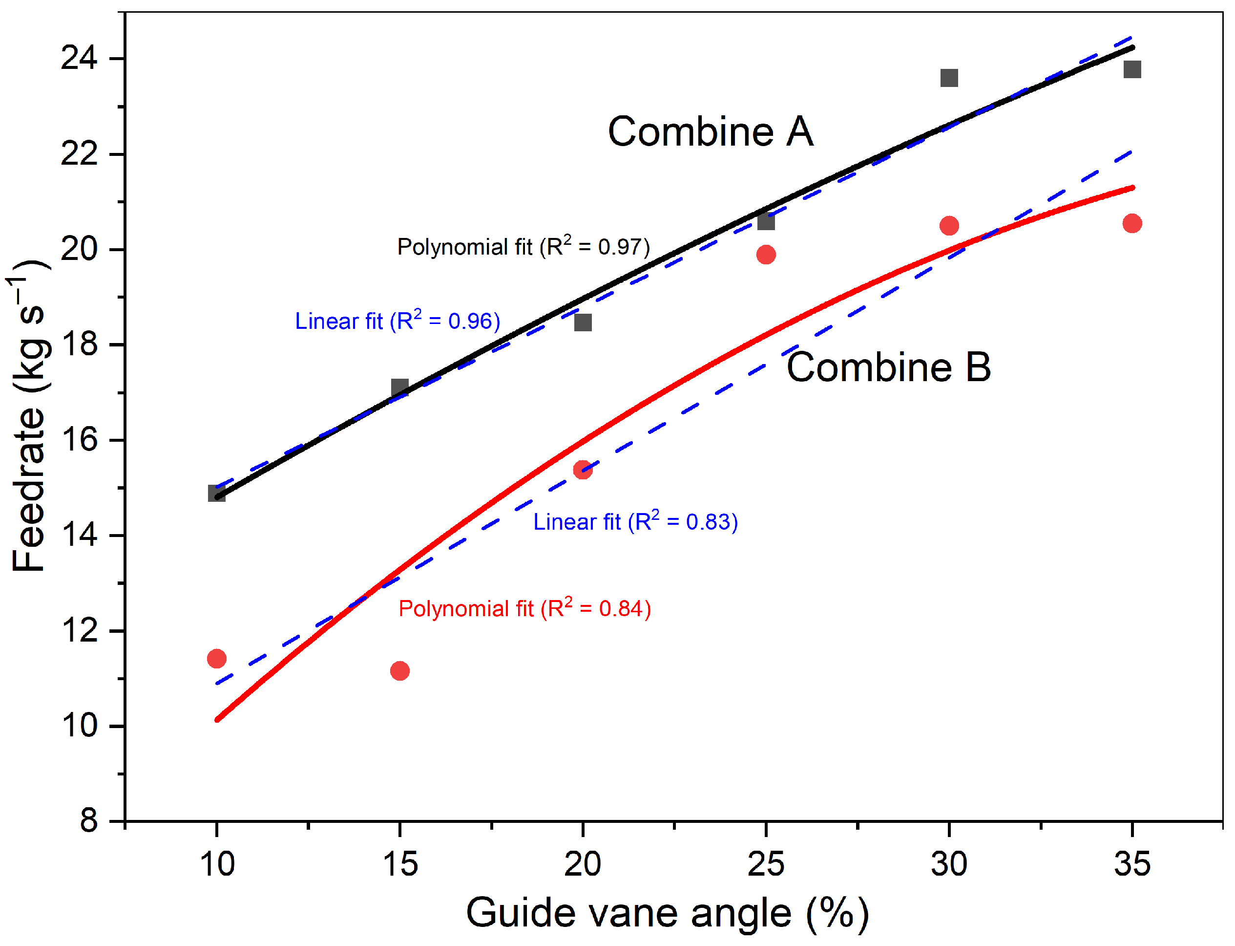
3.4. Throughput
Throughput is an indicator of combine harvester efficiency, representing the amount of crop material processed over time.
The feed rate (kg s−1) was assessed across six guide vane angle settings (10–35°) in both Combine A and Combine B. Engine load was maintained at approximately 90% for all trials, isolating guide vane angle as the primary variable influencing material flow.
Feed flow rates increased consistently with guide vane angle in both machines. Combine A recorded an increase from 14.89 kg s
−1 at 10° to 23.78 kg s
−1 at 35°, while Combine B increased from 11.42 kg s
−1 to 20.55 kg s
−1 over the same range. The Combine B throughput plateaued, rising only slightly from 19.89 kg s
−1 to 20.55 kg s
−1 from the 25–35° guide vane angle (
Figure 14). This diminishing return suggests that Combine B’s partially adjustable guide vane system had reached its functional limit in increasing throughput.
As shown in
Figure 14, Combine A exhibited a strong linear relationship between guide vane angle and feed rate (R
2 = 0.96), though the polynomial fit provided a better R
2 of 0.97. In contrast, Combine B showed better fit with a polynomial trend (R
2 = 0.84) compared to its linear counterpart (R
2 = 0.83), supporting the curvilinear behavior.
This confirms that larger vane angles accelerate material movement, enabling greater throughput even when engine power remains constant. The fully adjustable vane system in Combine A allowed for smoother and more uniform acceleration across the rotor length, resulting in a steeper and more efficient increase in feed rate compared to Combine B.
The advantage of Combine A became especially evident at mid-to-high vane angles (25–35°), where its improved material guidance minimized internal flow restrictions and allowed higher feed volume without excessive grain losses.
However, the increased throughput at higher vane inclinations came with trade-offs. As described in previous sections, separation and grain losses also increased beyond 30°, particularly in Combine A. This highlights a performance threshold: while a greater feed rate improves productivity, it also risks exceeding the separation system’s capacity, potentially leading to overloading, reduced cleaning efficiency, and increased losses.
The guide vane inclination had a pronounced influence on feed flow rate. Combine A’s full-length adjustable vane system enabled higher and more efficient throughput than Combine B, especially at 25–35°, by maintaining consistent axial flow throughout the rotor. A paired t-test was conducted to compare the feed flow rate between Combine A and Combine B across the tested vane angles. The results showed a statistical difference (t = 4.80, p = 0.0049), confirming that Combine A’s throughput advantage is not due to random variation. Nonetheless, the balance between throughput and grain retention must be carefully managed to avoid efficiency losses at higher flow rates.
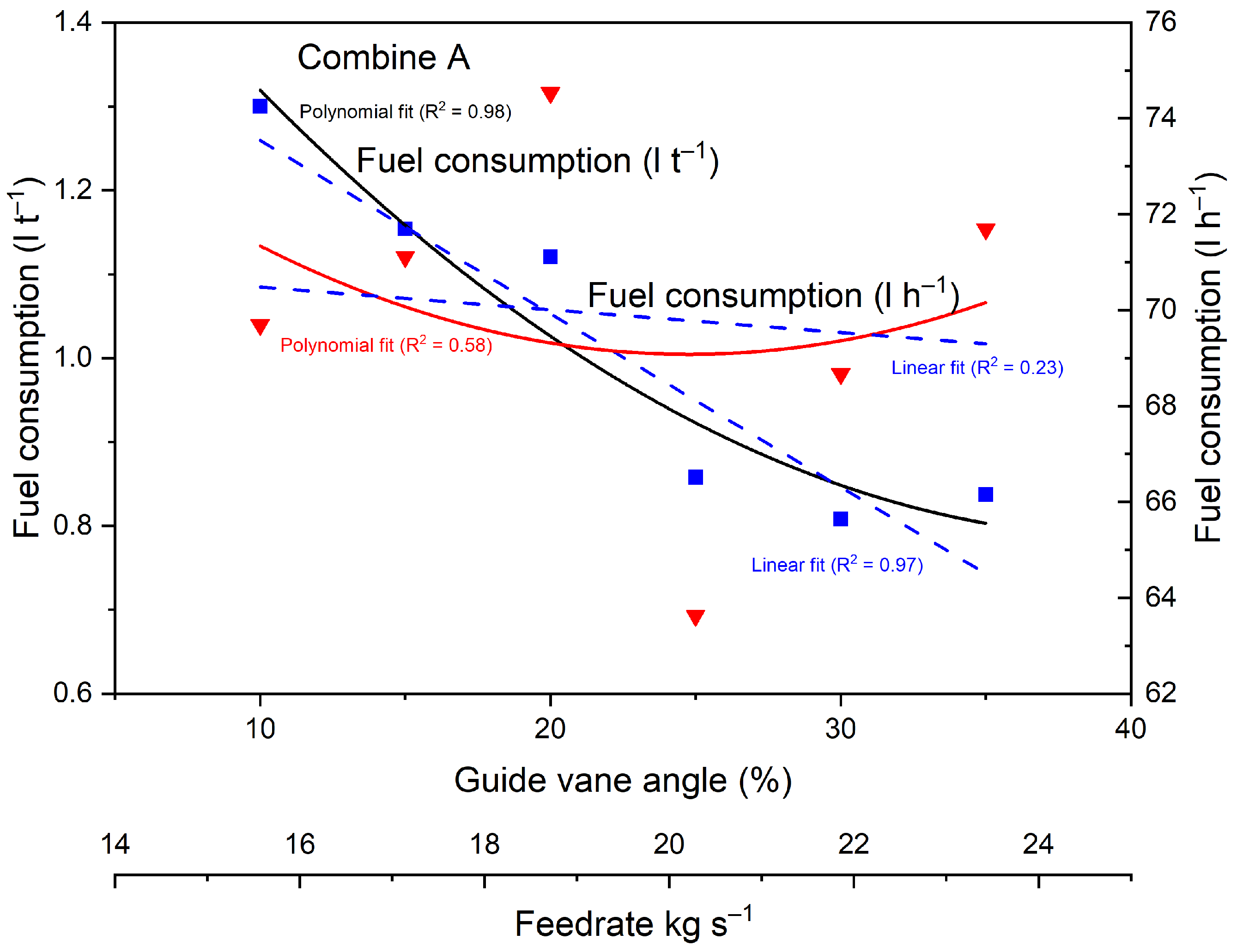
3.5. Fuel Consumption and Engine Load
Fuel consumption is a performance and economic metric in combine harvester operation. It reflects not only engine efficiency, but also how effectively the machine converts power into material throughput. The fuel consumption was evaluated both in absolute terms (L h−1) and relative to output (L t−1), across guide vane angles from 10–35°, with engine load maintained at approximately 90% for both Combine A and Combine B.
At low vane angles (10–15°), Combine A consumed 69.7–71.11 L h
−1, while Combine B showed slightly higher consumption at 74.89–78.9 L h
−1. This difference narrowed at mid-range settings (20–25°), where both machines began to operate more efficiently due to increased feed flow. The minimum absolute fuel consumption for Combine A was observed at 25°, at just 63.63 L h
−1, which coincided with a throughput of 20.6 kg s
−1 (
Figure 15 and
Figure 16). Combine B reached its lowest absolute fuel rate at 35° (73.6 L h
−1), but its output increase during this stage was limited.
When fuel efficiency is analyzed in terms of fuel consumed per ton of harvested grain (L t
−1), the differences between the two combines becomes more pronounced, as illustrated in
Figure 13. Combine A demonstrated better fuel-use efficiency across the entire guide vane range. At 25°, its specific consumption was just 0.86 L t
−1, while Combine B required 1.06 L t
−1 at the same setting. At 10°, Combine A used 1.30 L t
−1 versus 1.82 L t
−1 for Combine B, underscoring the higher energy cost of low-throughput operation.
For Combine A, polynomial regression provided a near-perfect fit for specific fuel consumption (R2 = 0.98), slightly outperforming the linear fit (R2 = 0.97). However, neither model fit the hourly fuel consumption data well, with R2 values of 0.58 and 0.23, respectively. This suggests that while guide vane angle has a measurable influence on fuel efficiency per ton, its effect on total hourly fuel use is limited.
For Combine B, polynomial regression produced stronger fits for both specific fuel consumption (R2 = 0.89) and hourly fuel use (R2 = 0.94), outperforming their respective linear fits (R2 = 0.81 and 0.71). These results indicate that fuel consumption behavior in Combine B is better represented by a curvilinear trend, reflecting nonlinear efficiency gains as guide vane angle increases.
The fuel efficiency in Combine A is attributed to its ability to maintain higher feed flow rates and smoother crop acceleration through the rotor. The full-length adjustable vanes optimize material progression, reducing torque fluctuations and internal resistance, which translates into lower fuel demand per unit of output. In contrast, Combine B’s segmented vane configuration likely created local flow inefficiencies, especially at high biomass intake levels, leading to more erratic engine load responses and higher relative fuel use.
While absolute fuel use in both machines increased again at higher vane angles (30–35°) due to elevated throughput and engine response demands, Combine A maintained more stable and efficient operation. At 35°, it delivered the highest throughput (23.78 kg s−1) at a low specific fuel rate of 0.84 L t−1 compared to Combine B, despite similar fuel consumption (1.08 L t−1) and achieved throughput (20.55 kg s−1).
In conclusion, these findings confirm that guide vane inclination affects fuel efficiency, and that fully adjustable guide vane systems—as used in Combine A—enable higher material handling performance while maintaining lower fuel cost per ton harvested.
3.6. Optimal Performance Range
Determining the optimal operational window for guide vane inclination is essential for balancing throughput, grain quality, separation efficiency, and fuel consumption in axial-flow combine harvesters. Based on the experimental results, both Combine A and Combine B demonstrated performance trade-offs across the tested guide vane range (10–35°), but the optimal settings differed due to their structural configurations.
For Combine A, the best overall performance was achieved in the 25–30° guide vane angle range. Within this interval, the machine maintained high throughput (8.42–8.9 t ha−1), low separation losses (0.96–1.62%), and exceptionally low broken grain values (0.71–0.25%). Specific fuel consumption also reached its minimum at 25°, at only 0.86 L t−1, confirming this angle as the most fuel-efficient setting. These favorable results are attributed to the fully adjustable guide vane system, which enabled uniform axial flow, minimized frictional stress, and optimized the exposure time for effective separation.
In contrast, Combine B reached its peak performance slightly earlier, around 25°, with throughput at 8.52 t ha−1 and separation loss at 0.91%. However, its broken grain percentage remained higher (1.12%), and fuel efficiency was lower at 1.06 L t−1. Beyond 25°, Combine B exhibited signs of diminishing returns: while feed rate increased marginally, separation and grain losses also rose, and the machine fuel efficiency gains began to plateau. This suggests that the segmented vane configuration limits effective adaptation to higher axial acceleration, particularly in the threshing zone.
The data indicate that Combine A offers a wider and more stable optimal range, with better performance sustainability as the guide vane angle increases. In contrast, Combine B’s optimal range is narrower, and further increases in vane angle lead to less predictable trade-offs between throughput and grain preservation.
In practical terms, these results suggest that for crops with similar density and moisture content as tested winter wheat, operators should prioritize 25–30° for Combine A and limit adjustments to ≤25° for Combine B to maintain optimal balance between capacity, fuel use, and grain quality.


