Abstract
Parametric Finite Element (FE) simulations were performed to investigate the ultimate flexural of different configurations of friction steel beam-to-column joints equipped with FREEDAM (free from damage) dampers. The main aim of this study was to compare the effectiveness of friction dampers featuring either single or multiple slotted holes, examining how these variations influence the behavior of the joint and the devices under seismic loads. In particular, the ultimate behavior of the connection (i.e., when the device reaches its maximum stroke) was investigated to characterize the involvement of the bolts in shear, the bearing of the plates, and the yielding of the supporting components. The analysis of bolt stress states revealed significant differences influenced by the number of bolts and slots. The FE models were calibrated against the experimental results obtained within the FREEDAM RFCS Project. These insights contribute to the design and performance evaluation of steel beam-to-column joints with FREEDAM connections, in particular the detailing of the haunch slots, laying the groundwork for future research and applications.
1. Introduction
The evolution of seismic design strategies for steel structures has increasingly focused on minimizing post-earthquake damage while ensuring structural integrity [1,2,3,4]. Modern seismic codes are mainly based on the application of the capacity design principles, i.e., distinguishing dissipative and non-dissipative zones. Dissipative zones are expected to undergo plastic deformations during earthquakes and are devoted to dissipating the energy, whereas non-dissipative zones must remain elastic to avoid brittle failure mechanisms. Such strategies, while effective in absorbing seismic energy, often result in structural damage that is economically and functionally debilitating.
Innovations in seismic design have led to the development and application of additional energy dissipation mechanisms, like friction dampers [5]. Steel beam-to-column joints equipped with friction devices dissipate seismic energy effectively and limit plastic deformations into replaceable elements. This approach aligns with the modern trend towards low-damage structures, which are increasingly preferred for their resilience and cost-effectiveness in seismic regions [6].
Friction dampers are characterized by their stable and predictable response and the localization of demand into easily replaceable parts, minimizing post-earthquake damage. This adaptability allows their integration into various structural configurations, making them one of the most promising solutions for seismic design. The effectiveness of these dampers has been validated through numerous studies and applications across seismic-prone regions, including Europe and Japan. Notably, European studies have focused on symmetric friction mechanisms [7,8] in contrast to the asymmetric friction mechanisms explored in New Zealand [9,10,11,12,13,14,15].
The design of moment-resisting frames (MRFs) with friction dampers offers significant advantages. It allows for decoupling the stiffness and the resistance of the joints, thus enabling full-rigid and partial-strength behavior in accordance with [16].
A pivotal advancement in seismic supplementary dissipation strategies is embodied in the FREEDAM (acronym of “free from damage”) devices (Figure 1), which are conceived to ensure that beam-to-column connections elastically behave even after severe seismic events, thereby preserving the structural integrity of buildings provided that the limit of the device stroke is not overcome.
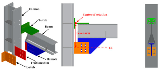
Figure 1.
FREEDAM beam-to-column joint.
The FREEDAM device is located under the lower beam flange and accommodates large slippage that allows a relative rotation between the beam and the column by enforcing a center of rotation in the stem of the upper T-Stub connecting the upper beam flange to the column. The slippage of the damper develops through vertical slotted holes located in the friction shims and horizontal slotted holes located in a haunch stiffener that is directly connected to the beam.
The local details of the damper may affect the rotation capacity of the beam-to-column assembly. In particular, the configuration of the slotted holes plays a key role in accommodating the slippage and in transferring the shear force to the connected members. Therefore, the study described in this paper aims to investigate the ultimate flexural behavior of FREEDAM connections, varying the details of the slotted holes, namely, the configuration with single slotted holes for a row of bolts is compared with a modified device with multiple slotted holes corresponding to the number of bolts. This second type of configuration has been designed to promote the bearing resistance of all bolts in the damper when its stroke is reached, and other secondary mechanisms may occur, e.g., the yielding of the beam [17], at the end of the haunch or local instability mechanisms in the web of the beam near the bolted haunch. Addressing the innovation of this research, it is pivotal to highlight that the comparative analysis of single versus multiple slotted holes configurations introduces a novel approach in enhancing the structural integrity and resilience of FREEDAM connections. This investigation not only sheds light on the mechanical behavior under varying conditions but also sets a precedent for the design and optimization of damper details, contributing significantly to the field of energy dissipation devices.
To achieve this goal, FEM simulations using the software ABAQUS (ver.2017) have been performed. Reference is made to the calibration reported in [7] and to the experimental and numerical results obtained in [18] where the devices with single-slotted holes for row of bolts have been investigated. A set of four friction dampers (FDs) was considered to cover different structural geometries that are representative of typical European multi-story steel MRFs. The analyses were performed under monotonic loading both in hogging and sagging flexural deformations. In Section 2, the set of the selected FDs is presented. In Section 3, the FE modeling of the devices is reported, while in Section 4, a discussion of the results is presented. Finally, based on the obtained results, the main conclusions are drawn.
2. Description of the Investigated Joints and Relevant Damper Configurations
The geometrical features of the investigated FREEDAM beam-to-column joints are summarized in Table 1 [18], where the following parameters are varied: (1) the number of bolts of the damper ; (2) the bolt diameter ; (3) the lever arm of the connection ; (4) the maximum and the minimum beam section; and (5) the maximum and the minimum column section.

Table 1.
Geometrical features of the investigated FREEDAM joints.
According to the scheme reported in Figure 2, the design force of the friction damper can be derived as follows:
where is the plastic moment of the beam, and is the bending utilization factor, ranging from 0.3 to 0.6. A thorough investigation of the maximum and minimum values of has been formerly conducted in [7,18].
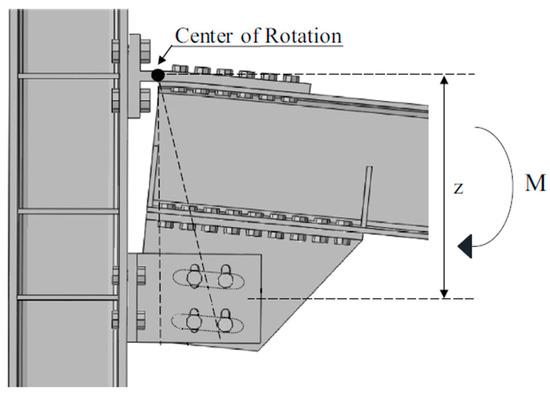
Figure 2.
FREEDAM beam-to-column joint: mechanical scheme.
The selection of the minimum value is driven by the consideration that values below this threshold do not satisfy the sliding resistance requirements of the damper for the ultimate limit state in non-seismic conditions. The upper limit of is derived by the requirement to maintain the beam within the elastic range and enhance the stiffness of the MRF, ensuring compliance with EC8 criteria concerning drift and P-delta effects.
The friction resistance, on the other hand, is defined as follows:
where is the design bolt preload, is the number of friction surfaces, is the characteristic static friction coefficient, and is the safety factor accounting for the loss of initial preload due to short-term and long-term relaxation phenomena. More details regarding the meaning of the terms and the suggested values are reported in [19].
After defining the geometric characteristics, the design force of the friction damper, and the friction resistance, a design chart was created (in collaboration with the FIP MEC company) where the required damper type is expressed based on the beam section and the bending utilization factor, as reported in Table 2.
Table 2.
Design chart: bending utilization factor and the beam size.
The analyzed dampers have been labeled D1A, D2B, D2C, and D3B. In accordance with Table 1 and Table 2, associations were made between devices and the beam and column sections of the node. In Table 3, the features of the analyzed dampers, i.e., the length of the column Lcolumn and the half-length of the beam Lbeam/2, are reported. As reported in Section 1, the simulations involved two configurations of the study setup, characterized by a different haunch, (1) single-slot haunch and (2) multiple-slot haunch, as reported in Figure 3. In Table 4, the main dimensions of the various components are reported (haunch, T-stub, L-stub) with reference to Figure 4.
Table 3.
Features of the analyzed dampers.
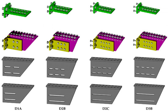
Figure 3.
Details of the upper and lower connections.
Table 4.
Dimensions of the upper and lower connections.
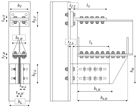
Figure 4.
Schematic representation of the beam-to-column joints and relevant geometric parameters.
The friction shim has the same width and height as the L-stub web and a thickness of 8 mm. The hole dimensions for the plates of the various components, given the size of the bolts, have been calculated according to EN 1993-1-3 standards [20]. The lengths of the horizontal slotted holes in the multiple-slotted haunches was calculated assuming a minimum rotation value of the connection greater than 0.035 radians in order to comply with highly ductile systems according to [16].
In particular, the rotation value used in the examined configurations was set to 0.04 rad to provide extra ductility. Given the rotation value, the maximum stroke that each bolt can undergo was calculated, based on simple geometric considerations. In fact, according to Figure 5, the maximum stroke per bolt is conservatively equal to the product of the distance between the center of rotation and the bolts centroid ( and the predefined rotation value (). Table 5 reports the half-lengths of the slots obtained according to the previous assumptions and their design values established with a 1% tolerance to ensure at least the predefined rotation (Equation (3)), accounting for assembly and manufacturing defects in the various components of the joint. In other words, the minimum half length of the single-slotted hole is equal to
where is the distance between the bolt rows (( as reported in Figure 5) and the horizontal axis passing through the center of rotation, and is the bolt hole clearance.
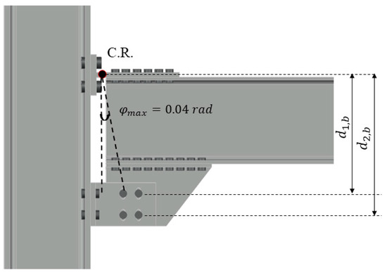
Figure 5.
Geometric scheme for the definition of stroke.
Table 5.
Dimensions of the parts constituting the damper.
3. Finite Element Modeling
The finite element simulations were performed through the software ABAQUS [21] and the analyses were carried out through a dynamic implicit quasi-static solver. All components were meshed by means of solid C3D8R elements, an 8-node linear brick with reduced integration. Mesh sizes were determined through sensitivity analyses, resulting in maximum dimensions of 5 mm, 10 mm, and 20 mm for bolts, plates, and steel profiles, respectively. A proper partitioning allowed the use of a structured hex pattern (Figure 6a). A stress-based mesh refinement algorithm has been implemented in the software.
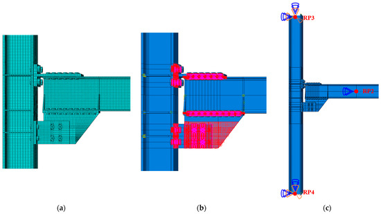
Figure 6.
FE model: (a) mesh pattern; (b) interaction zones; (c) boundary conditions.
The plastic behavior of steel parts was simulated based on the von Mises yield criterion with combined hardening. The elastic properties and the true stress–true strain curves for S355 steel grade were established through coupon tests conducted in [22]. The bolts were modeled by meshing a solid cylinder with the nominal circular gross area of the bolt. Equivalent true stress–true strain curves for the bolts have been derived from data presented in [23,24].
The interactions between contacting surfaces (e.g., bolt-to-plates, plate-to-plate) have been simulated, considering both “Normal” and “Tangential” behaviors. The former was implemented using the “Hard Contact,” while the latter was modeled differently for steel-to-steel interfaces and friction pad-to-steel interfaces (Figure 6b). A friction coefficient of 0.3 was employed for steel-to-steel surfaces, while a coefficient of 0.53 has been defined for the pad. Bolt pre-tensioning was modeled using the “Bolt load” option, applied in the initial analysis step with no other external actions. The preload in the bolts of the friction damper was assumed equal to the corresponding design value, while the preload recommended by EN1993 1–8 [16] was applied to all other bolts. Boundary conditions were consistently modeled as in [7], namely as follows: (i) the column was pinned at the lower end, releasing all flexural rotations and vertical displacements at the upper end, allowing the column to deform freely along its axis; (ii) the beam tip was simply pinned in the initial step, and the beam was additionally restrained against lateral-torsional buckling by introducing torsional restraints spaced according to [20]. Monotonic displacement histories were applied at the beam tip in a vertical direction.
4. Results and Discussion
The results of the FE analyses are shown both in terms of normalized moment–rotation curves for characterizing the monotonic behavior of the joint in hogging and sagging and stresses and deformations of the model to determine the onset of local mechanisms and weak elements. In both cases, a comparison will be made between single-slotted holes and a multiple-slotted holes.
The normalized bending moment was defined as
where is the bending moment at the column face.
From Figure 7, Figure 8, Figure 9 and Figure 10, it is possible to identify the normalized moment–damper rotation (intended as the rotation of the whole friction device with respect to the center of rotation) law in four main branches, for both hogging and sagging flexural deformations: (1) the first elastic branch; (2) the first plateau phase, due to the sliding of the device; (3) the second elastic phase, whose stiffness depends on the involvement of end-of-stroke engaged bolts; and (4) the second plateau phase, due to local mechanisms, such as the yielding of the beam near the haunch (Figure 11a), the yielding of bolted L-Stubs or T-Stubs (Figure 11b), the tensile failure of bolts connecting T-Stubs (Figure 12) and L-Stubs (Figure 13), the bearing of the slotted plate following contact with the bolt shank, or the bolt shear failure (Figure 14). These observations arise from the knowledge of the components constituting the node, supported by the results of the FE analysis and the findings reported in [18].
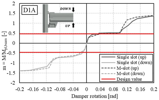
Figure 7.
D1A normalized bending moment–rotation curve.
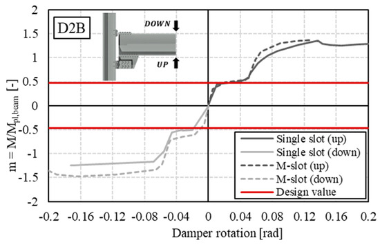
Figure 8.
D2B normalized bending moment–rotation curve.
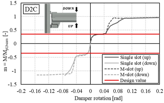
Figure 9.
D2C normalized bending moment–rotation curve.
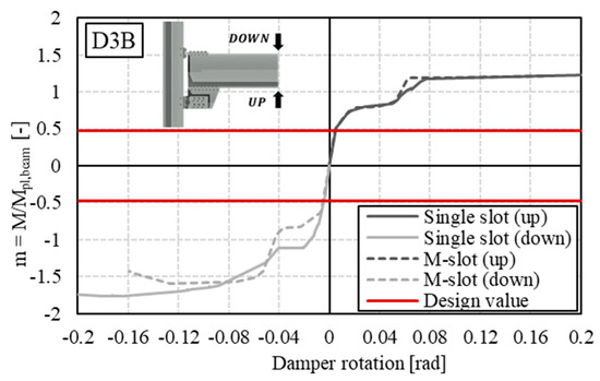
Figure 10.
D3B normalized bending moment–rotation curve.
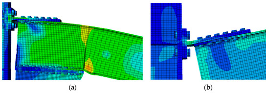
Figure 11.
Failure of local mechanisms: (a) plasticization of the beam; (b) plasticization of the T-stub.
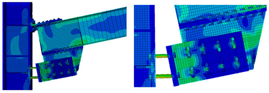
Figure 12.
Failure of local mechanisms: tensile failure of L-stub bolts.
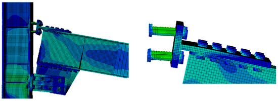
Figure 13.
Failure of local mechanisms: tensile failure of T-stub bolts.
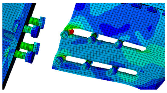
Figure 14.
Failure of local mechanisms: bearing of the slotted plate.
Comparing the results obtained for the single-slotted holes and multiple-slotted holes models in phase 1, a nearly similar slope can be observed, except for assembly D2B, which appeared slightly stiffer. Regarding the maximum value in terms of the normalized bending moment, only assembly D3B showed significantly higher values for hogging in the first branch. Furthermore, it can be observed that the representative line of the design Bending Utilization Factor in all analyzed cases intersects with the first elastic branch, indicating the effectiveness of the adopted design assumptions. Regarding the second elastic branch, the multiple-slot haunch joints generally exhibited higher stiffness, due to the involvement of a greater number of bolts in the end-of-stroke resisting mechanism.
This objective can be pursued by calibrating the hole sizes based on the geometry of the device and their positions, considering the center of rotation. Without this consideration, the result would be comparable to the single-slot model, where the first row of bolts is predominantly involved. Obviously, this effect becomes more significant as the number of bolts and slots increase, whose edges act as constraints allowing the bolts to exert their shearing action. In fact, notable differences can be observed for cases with 6 (D2B) and 8 bolts (D2C, D3B). These results are highlighted in Figure 15, Figure 16, Figure 17, Figure 18, Figure 19 and Figure 20, where the equivalent stress state of the bolts at the end of the analysis can be observed. From the performed analyses, specific quantities describing the behavior of the joints were derived, namely and as the slopes of the first and second elastic branches, respectively; and as the corresponding normalized bending moment at the maximum rotation achieved in the first and second elastic branches; and , which represents the normalized bending moment at the design rotation. A summary of the monitored mechanical parameters from FE analyses is reported in Table 6.
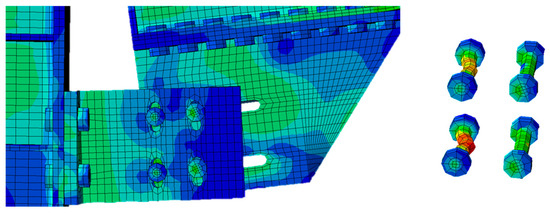
Figure 15.
D1A single-slotted: stress distribution on bolts.
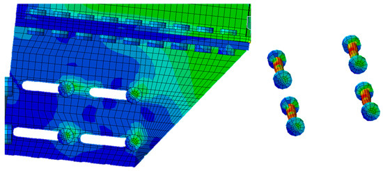
Figure 16.
D1A multiple-slotted: stress distribution on bolts.
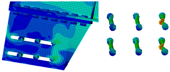
Figure 17.
D2B single-slotted: stress distribution on bolts.
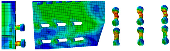
Figure 18.
D2B multiple-slotted: stress distribution on bolts.
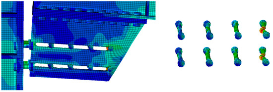
Figure 19.
D3B single-slotted: stress distribution on bolts.
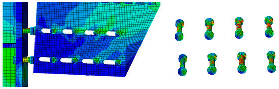
Figure 20.
D3B multiple-slotted: stress distribution on bolts.
Table 6.
Summarized results from the FE analyses.
5. Conclusions
This study conducted a detailed parametric analysis using Finite Element (FE) simulations to evaluate the behavior of steel beam-to-column joints equipped with FREEDAM dampers, with a focus on European Moment Resisting Frames (MRFs). Through rigorous calibration with experimental data from the RFCS Project FREEDAM, the accuracy of our simulation results has been ensured. The investigation has led to several key findings:
- The behavior of moment-rotation curves in both hogging and sagging conditions follows four distinct phases, indicating the critical phases of joint performance.
- Consistent stiffness was observed in the first elastic phase across different assemblies, with the D2B assembly showing slightly higher stiffness, highlighting the importance of the assembly configuration.
- Joints with multiple-slot dampers exhibited increased stiffness in the second elastic phase due to the engagement of a larger number of bolts, underscoring the effectiveness of the damper design.
- The calibration of hole sizes, tailored to the damper’s geometry and positioning, is crucial for optimizing performance, emphasizing the need for precise design considerations.
- Based on the insights gained from this research, the primary recommendation is to carefully size the slots according to the detailed explanations provided in Section 2 with reference to Equation (3).
- Future experimental testing, particularly focusing on multiple-slot configurations, is advocated to validate these findings and further refine damper designs for enhanced seismic resilience of steel structures.
Author Contributions
Conceptualization, V.P., E.N. and R.M.; Methodology, M.D., V.P. and R.M.; Software, M.D. and P.T.; Validation, E.N., M.D. and P.T.; Formal analysis, E.N. and P.T.; Investigation, E.N. and P.T.; Writing—original draft, E.N. and P.T.; Writing—review and editing, M.D. and P.T.; Supervision, M.D., V.P. and R.M. All authors have read and agreed to the published version of the manuscript.
Funding
This research was funded by RFCS Dreamers, grant number 101034015.
Institutional Review Board Statement
Not applicable.
Informed Consent Statement
Not applicable.
Data Availability Statement
The data presented in this study are available in the article.
Conflicts of Interest
The authors declare no conflicts of interest. The funders had no role in the design of the study; in the collection, analyses, or interpretation of data; in the writing of the manuscript; or in the decision to publish the results.
Nomenclature
| Number of bolts in the damper | |
| Bolt diameter | |
| Lever arm of the connection | |
| Bending utilization factor | |
| Plastic moment of the beam | |
| Friction resistance | |
| Design bolt preload | |
| Number of friction surfaces | |
| Characteristic static friction coefficient | |
| Safety factor for the loss of initial preload | |
| Lcolumn | Length of the column |
| Lbeam | Length of the beam |
| Superior base of the haunch | |
| Inferior base of the haunch | |
| Height of the haunch | |
| Base of the haunch flange | |
| Thickness of the haunch flange | |
| Thickness of the web flange | |
| Base of the T-stub | |
| Height of the T-stub flange | |
| Thickness of the T-stub flange | |
| Length of the T-stub | |
| Thickness of the T-stub web | |
| Base of the L-stub | |
| Height of the L-stub flange | |
| Thickness of the L-stub flange | |
| Length of the L-stub | |
| Thickness of the L-stub web | |
| Distance between the center of rotation and the bolts centroid | |
| Design rotation | |
| Bolt hole clearance | |
| Half-lengths of the slots | |
| Slope of the first elastic branch | |
| Slope of the second elastic branch | |
| Maximum normalized bending moment (1st branch) | |
| Maximum normalized bending moment (2nd branch) | |
| Normalized bending moment at the design rotation |
References
- Montuori, R.; Nastri, E.; Piluso, V. Theory of plastic mechanism control: A new approach for the optimization of seismic resistant steel frames. Earthq. Eng. Struct. Dyn. 2022, 51, 3598–3619. [Google Scholar] [CrossRef]
- Montuori, R.; Nastri, E.; Todisco, P. Influence of the seismic shear proportioning factor on steel MRFs seismic performances. Soil Dyn. Earthq. Eng. 2021, 141, 106498. [Google Scholar] [CrossRef]
- Piluso, V.; Pisapia, A.; Castaldo, P.; Nastri, E. Probabilistic Theory of Plastic Mechanism Control for Steel Moment Resisting Frames. Struct. Saf. 2019, 76, 95–107. [Google Scholar] [CrossRef]
- Dell’Aglio, G.; Montuori, R.; Nastri, E.; Piluso, V. A critical review of plastic design approaches for failure mode control of steel moment resisting frames. Ing. Sismica 2017, 34, 82–102. [Google Scholar]
- Grigorian, C.E.; Yang, T.S.; Popov, E.P. Slotted bolted connection energy dissipators. Earthq. Spectra 1993, 9, 491–504. [Google Scholar] [CrossRef]
- Soong, T.T.; Spencer, B.F. Supplemental energy dissipation: State-of-the-art and state of-the-practice. Eng. Struct. 2002, 24, 243–259. [Google Scholar] [CrossRef]
- Tartaglia, R.; D’Aniello, M.; Campiche, A.; Latour, M. Symmetric friction dampers in beam-to-column joints for low-damage steel MRFs. J. Constr. Steel Res. 2021, 184, 106791. [Google Scholar] [CrossRef]
- Ferrante Cavallaro, G.; Francavilla, A.B.; Latour, M.; Piluso, V.; Rizzano, G. Cyclic response of low yielding connections using different friction materials. Soil Dyn. Earthq. Eng. 2018, 114, 404–423. [Google Scholar] [CrossRef]
- MacKinven, H. Sliding Hinge Joint for Steel Moment Frames Experimental Testing; ENCI 493 Project Report; Department of Civil Engineering, University of Canterbury: Canterbury, UK, 2006. [Google Scholar]
- MacRae, G.A.; MacKinven, H.; Clifton, G.C.; Pampanin, S.; Walpole, W.; Butterworth, J. Tests of sliding hinge joints for steel moment frames. In Proceedings of the 8th Pacific Structural Steel Conference—Steel Structures in Natural Hazards, PSSC 2007, Wairakei, New Zealand, 13–16 March 2007; Volume 2, pp. 109–114. [Google Scholar]
- Butterworth, J.; Clifton, C.; MacRae, G. Developments in steel frame joints in New Zealand. Struct. Eng. 2008, 86, 20–21. [Google Scholar]
- Khoo, H.H.; Clifton, C.; Butterworth, J.; MacRae, G.; Ferguson, G. Influence of steel shim hardness on the sliding hinge joint performance. J. Construct. Steel Res. 2012, 72, 119–129. [Google Scholar] [CrossRef]
- MacRae, G.A.; Clifton, G.C.; Mackinven, H.; Mago, N.; Butterworth, J.; Pampanin, S. The sliding hinge joint moment connection. Bull. N. Z. Soc. Earthq. Eng. 2010, 43, 202–212. [Google Scholar] [CrossRef]
- Ramhormozian, S.; Clifton, G.C.; MacRae, G.A. The Asymmetric Friction Connection with Belleville Springs in the Sliding Hinge Joint. In Proceedings of the 2014 New Zealand Society for Earthquake Engineering (NZSEE) Annual Technical Conference, Auckland, Australia, 21–23 March 2014. [Google Scholar]
- Ramhormozian, S.; Clifton, G.C.; Nguyen, H.; Cowle, K. Determination of the Required Part-Turn of the Nut with Respect to the Number of Free Threads under the Loaded Face of the Nut in Fully Tensioned High Strength Friction Grip Property Class 8.8 Bolts. In Proceedings of the Steel Innovations Conference, Auckland, New Zealand, 3–4 September 2015. [Google Scholar]
- CEN EN 1993:1-8; Design of Steel Structures—Part 1–8: Design of Joints. European Committee for Standardization: Brussels, Belgium, 2005.
- Di Lauro, F.; Montuori, R.; Nastri, E.; Piluso, V. Partial safety factors and overstrength coefficient evaluation for the design of connections equipped with friction dampers. Eng. Struct. 2019, 178, 645–655. [Google Scholar] [CrossRef]
- Piluso, V.; Rizzano, G.; Latour, M.; Francavilla, A.; Di Benedetto, S.; Landolfo, R.; D’Aniello, M.; da Silva, L.S.; Santiago, A.; Santos, A.; et al. Informative Documents of the Dissemination Project FREEDAM-PLUS. GA 899321-2020. Available online: https://www.steelconstruct.com/eu-projects/freedam-2/documents/ (accessed on 1 May 2021).
- Nastri, E.; D’Aniello, M.; Zimbru, M.; Streppone, S.; Landolfo, R.; Montuori, R.; Piluso, V. Seismic response of steel moment resisting frames equipped with friction beam-to-column joints. Soil Dyn. Earthq. Eng. 2019, 119, 144–157. [Google Scholar] [CrossRef]
- CEN EN 1993-1-3; Eurocode 3—Design of Steel Structures—Part 1–1: General Rules and Rules for Buildings. European Committee for Standardization: Brussels, Belgium, 2005.
- Dassault. Abaqus 6.17—Abaqus Analysis User’s Manual; Dassault Systèmes Simulia Corp.: Johnston, RI, USA, 2017. [Google Scholar]
- Latour, M.; D’Aniello, M.; Zimbru, M.; Rizzano, G.; Piluso, V.; Landolfo, R. Removable friction dampers for low-damage steel beam-to-column joints. Soil Dyn. Earthq. Eng. 2018, 115, 66–81. [Google Scholar] [CrossRef]
- D’Aniello, M.; Cassiano, D.; Landolfo, R. Monotonic and cyclic inelastic tensile response of European preloadable GR10.9 bolt assemblies. J. Constr. Steel Res. 2016, 124, 77–90. [Google Scholar] [CrossRef]
- D’Aniello, M.; Cassiano, D.; Landolfo, R. Simplified criteria for finite element modeling of European preloadable bolts. Steel Comp Struct 2017, 24, 643–658. [Google Scholar]
Disclaimer/Publisher’s Note: The statements, opinions and data contained in all publications are solely those of the individual author(s) and contributor(s) and not of MDPI and/or the editor(s). MDPI and/or the editor(s) disclaim responsibility for any injury to people or property resulting from any ideas, methods, instructions or products referred to in the content. |
© 2024 by the authors. Licensee MDPI, Basel, Switzerland. This article is an open access article distributed under the terms and conditions of the Creative Commons Attribution (CC BY) license (https://creativecommons.org/licenses/by/4.0/).