Abstract
The increase of popularity of reactivity-controlled compression ignition (RCCI) is attributed to its capability of achieving ultra-low nitrogen oxides (NOx) and soot emissions with high brake thermal efficiency (BTE). The complex and nonlinear nature of the RCCI combustion makes it challenging for model-based control design. In this work, a model-based control system is developed to control the combustion phasing and the indicated mean effective pressure (IMEP) of RCCI combustion through the adjustments of total fuel energy and blend ratio (BR) in fuel injection. A physics-based nonlinear control-oriented model (COM) is developed to predict the main combustion performance indicators of an RCCI marine engine. The model is validated against a detailed thermo-kinetic multizone model. A novel linear parameter-varying (LPV) model coupled with a model predictive controller (MPC) is utilized to control the aforementioned parameters of the developed COM. The developed system is able to control combustion phasing and IMEP with a tracking error that is within a 5% error margin for nominal and transient engine operating conditions. The developed control system promotes the adoption of RCCI combustion in commercial marine engines.
1. Introduction
Maritime transport covers the majority of global trade; 77% of external and 35% of internal trade of the European Union (EU) is transported by sea. Despite its economic benefits, marine transportation is a major source of emissions [1]. Maritime transportation is a source of pollutants such as nitrogen oxides (NOx), carbon dioxide (CO2), sulphur dioxide (SO2), unburned hydrocarbons (UHC) and particulate matter (PM). These pollutants have detrimental effects on both environment and human health, impacting regions beyond just coastal areas [2]. The emissions of transportation sector in Europe has rebounded by 8.6% since the COVID-pandemic and has further increased by 2.7% since 2022. The levels especially in aviation and maritime sector are expected to further increase in the upcoming years [3]. The latest mandatory energy efficiency improvement set by the International Maritime Organization (IMO) covers a diverse range of design, operational and economic solutions, such as alternative fuels, hybridization of propulsion systems, as well as voyage and speed optimization [4].
As the regulations of maritime combustion engine emissions have become stricter over the years, new and more advanced combustion processes have been a great area of interest within the research communities. Low-temperature combustion (LTC) processes have been utilized in the next generation of combustion engines, not only in maritime sector, but also in off- and on-road sectors due to their high efficiency [5]. LTC techniques include homogeneous charge compression ignition (HCCI), premixed charge compression ignition (PCCI), partially premixed combustion (PPC) and reactivity controlled compression ignition (RCCI), among other techniques. The superiority of RCCI compared to other LTC techniques can be explained by its ability to achieve higher brake thermal efficiency (BTE) while maintaining low NOx and PM levels [6]. Additionally, a 25% reduction of CO2 has been observed with biofuels [7] and contemporary research proceeds towards flexible accommodation of hydrogen as low reactivity fuel [8].
Although the RCCI concept has numerous advantages and benefits, there exist certain challenges regarding its practical adoption. These challenges are:
- High dependency of auto-ignition on the conditions at inlet valve closing (IVC), making the real-time combustion control a challenging task [9].
- Excessive maximum in-cylinder pressure (), maximum pressure rise rate (), knock and noise at high engine loads, which reduce the effective operating range as well as increases the emission of UHC [10]
- Increase of hydrocarbons (HC) and carbon monoxide (CO) emissions at low engine loads [11]
- Combustion stability issues at transient operating conditions
- Overall complex and nonlinear nature of the RCCI process itself
Model-based control of RCCI combustion has gained popularity over the past decade. Many works have concentrated on light- and heavy-duty engines. Sadabadi et al. [12,13] developed a physics-based control-oriented model (COM) for RCCI combustion capable of predicting main combustion indicators such as start of combustion (), burn duration (), combustion phasing () and indicated mean effective pressure (IMEP). This model has been widely applied in works covering model-based control of RCCI process. An important characteristic of RCCI fuel blend of low- and high-reactivity fuel (LRF, HRF) [14] is the fact that it is highly correlated with the formation CO and HC [15]. Initial works include controlling with a PI-controller using blend ratio (BR) and start of injection () as control signals achieving low steady state error and settling time of 3–4 cycles [16]. Sadabadi et al. [17] controlled the combustion phasing, i.e., of an RCCI engine with a linear-quadratic-integrator (LQI) controller achieving an overshoot below 1 °CA, a 0 °CA steady state error and a settling time of 6 cycles. Raut et al. [18] adopted a model-predictive controller (MPC) for an RCCI engine, where and IMEP were controlled by BR and . A rise time of 2 cycles with relatively low steady state error for and IMEP were achieved with a single MPC. Their switched MPCs achieved a steady error of 1.3 °CA and 23.8 kPa for and IMEP, respectively. In [19] a support vector machine (SVM) based data-based model was developed to estimate linear parameter-varying (LPV) models for RCCI combustion enabling real-time control. The model was used in their MPC framework to control with achieving a steady state error below 1 °CA and settling time of 3 cycles. Irdmusa et al. have further developed their data-based LPV model to estimate [20], fuel stratification [21] and identifying RCCI states [22] for their control framework.
In [23], an optimal controller was developed to control the in-cylinder pressure and, subsequently, to evaluate the thermal efficiency using total fuel energy, BR and as control signals to achieve an optimal fuel path. Guardiola et al. [24] controlled IMEP, and combustion centroid (CC) with PI-controllers obtaining a steady state error of 0.13 bar, 0.5 °CA and 0.52 bar/°CA for IMEP, CC and , respectively. Unlike most of the aforementioned works, which focus mostly on controlling the fuel path of an RCCI engine, Verhaegh et al. [15] developed a robust multi-input and multiple-output (MIMO) feedback control methodology to control the airpath of an RCCI engine using fuel quantities, , variable geometry turbocharger (VGT) and exhaust gas recirculation (EGR) valve positions to control emission, and for transient engine operating conditions. Their closed-loop system achieved tracking errors of 0.24 bar and 0.45 °CA for IMEP and , respectively, while reducing emission by 12.8% and by 3.8 bar/°CA with respect to baseline conditions.
Marine engines have also traversed towards the RCCI within the field of low-temperature combustion in the recent years. Many novel modeling methodologies have been developed, especially in the form of multizone models (MZM) [5,25,
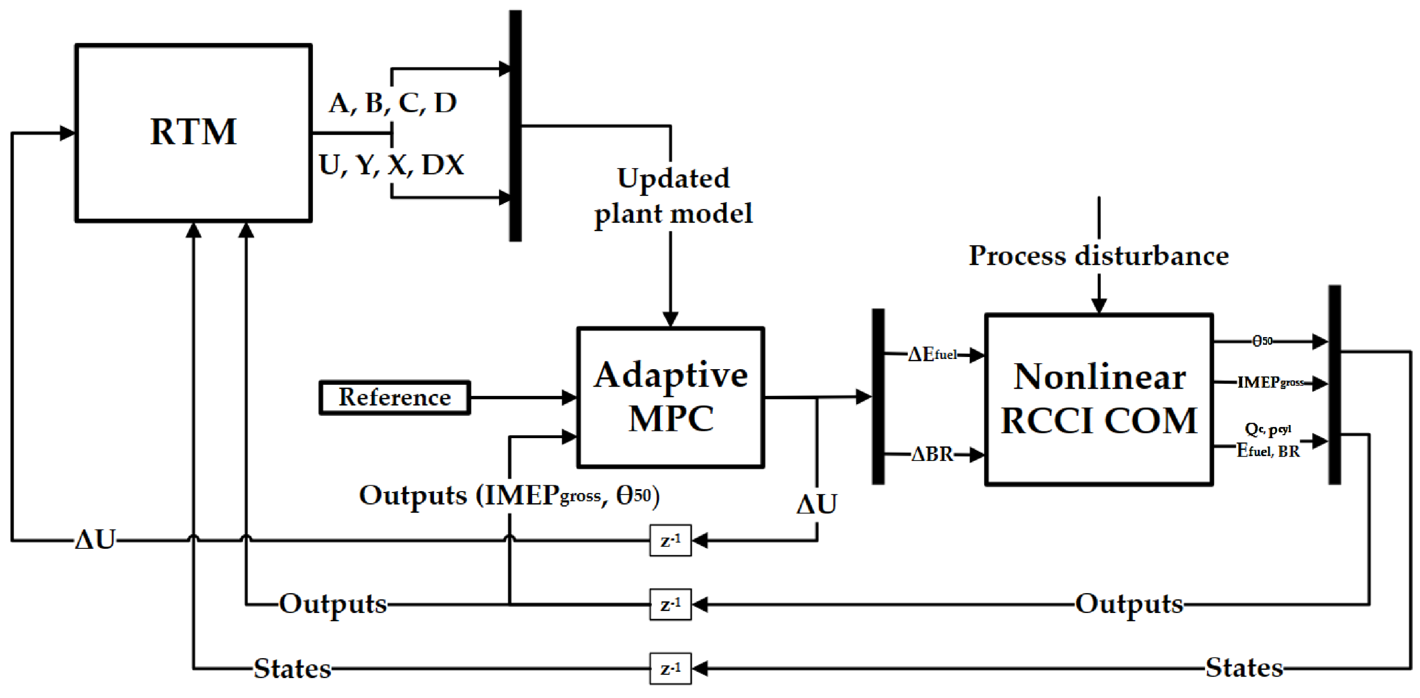
26]. However, the model-based control of RCCI combustion is at its initial stage in non-road and marine sector. It is also worth mentioning that the current multizone models could be used as plant models for RCCI control, but they do not enable real-time simulations due to their long calculation times. To the authors’ knowledge, this is the first paper that covers model-predictive control of RCCI combustion for marine engines. The work presents a MIMO control system consisting of a phenomenological RCCI combustion model, a state-of-the-art LPV model called the real-time model (RTM) [14] capable of simulation time in order of milliseconds and an adaptive MPC, which updates the aforementioned RTM for each engine operating condition and their transient. The main contributions of this work compared to previous studies are:
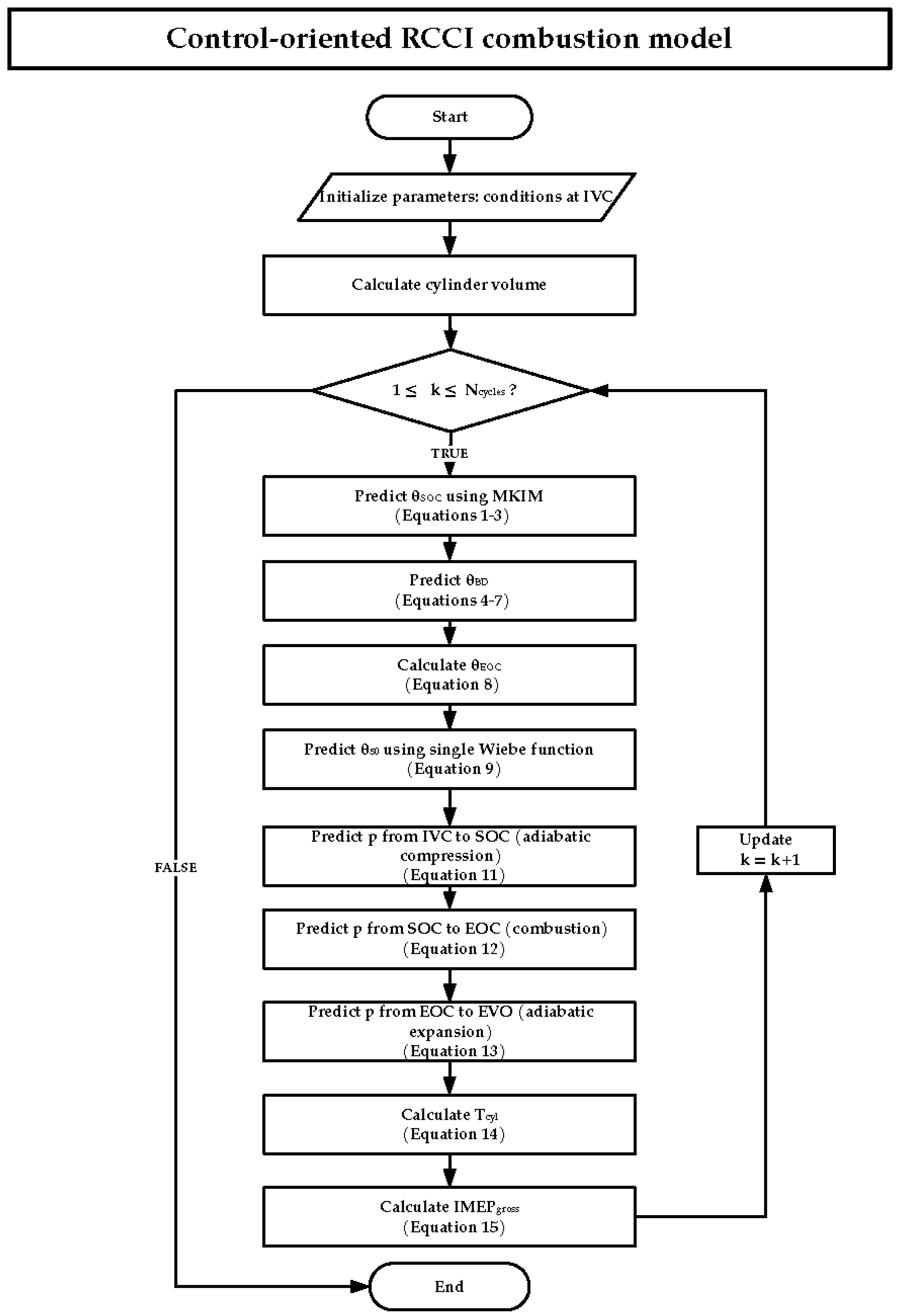
- A nonlinear, phenomenological RCCI COM for predicting main combustion indicators in the order of milliseconds, both crank angle - and cycle-wise. Furthermore, the model has predictive capabilities in both nominal and transient engine operating conditions.
- Model-in-loop validation of MPC system based on the RTM model to control combustion phasing and IMEP with the nonlinear RCCI COM as plant model. The validation is done in both nominal and transient engine operating conditions.
This paper is organised in the following manner: Section 2 presents the methodology. Specifically, Section 2.1 provides details on the nonlinear RCCI COM, which is used as a plant model in the control system. The COM is a simplified version of the University of Vaasa Advanced Thermokinetic Multizone (UVATZ) model. Section 2.2 describes the controller and the control problem. Section 2.3 presents the experimental data and the UVATZ model, which is used as the source of reference data for the developed control system. The results of the developed system are presented in Section 3, where 
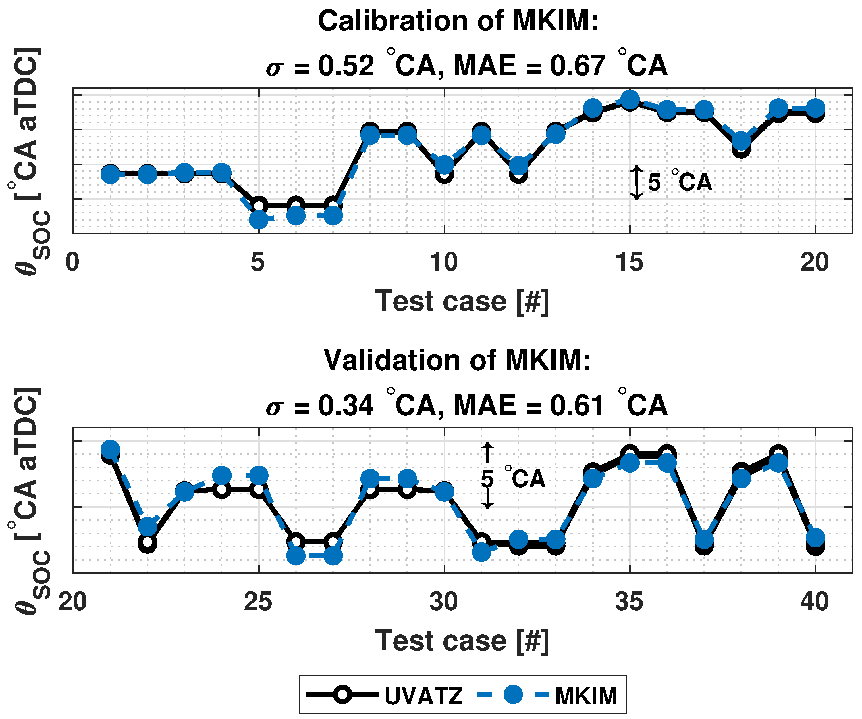
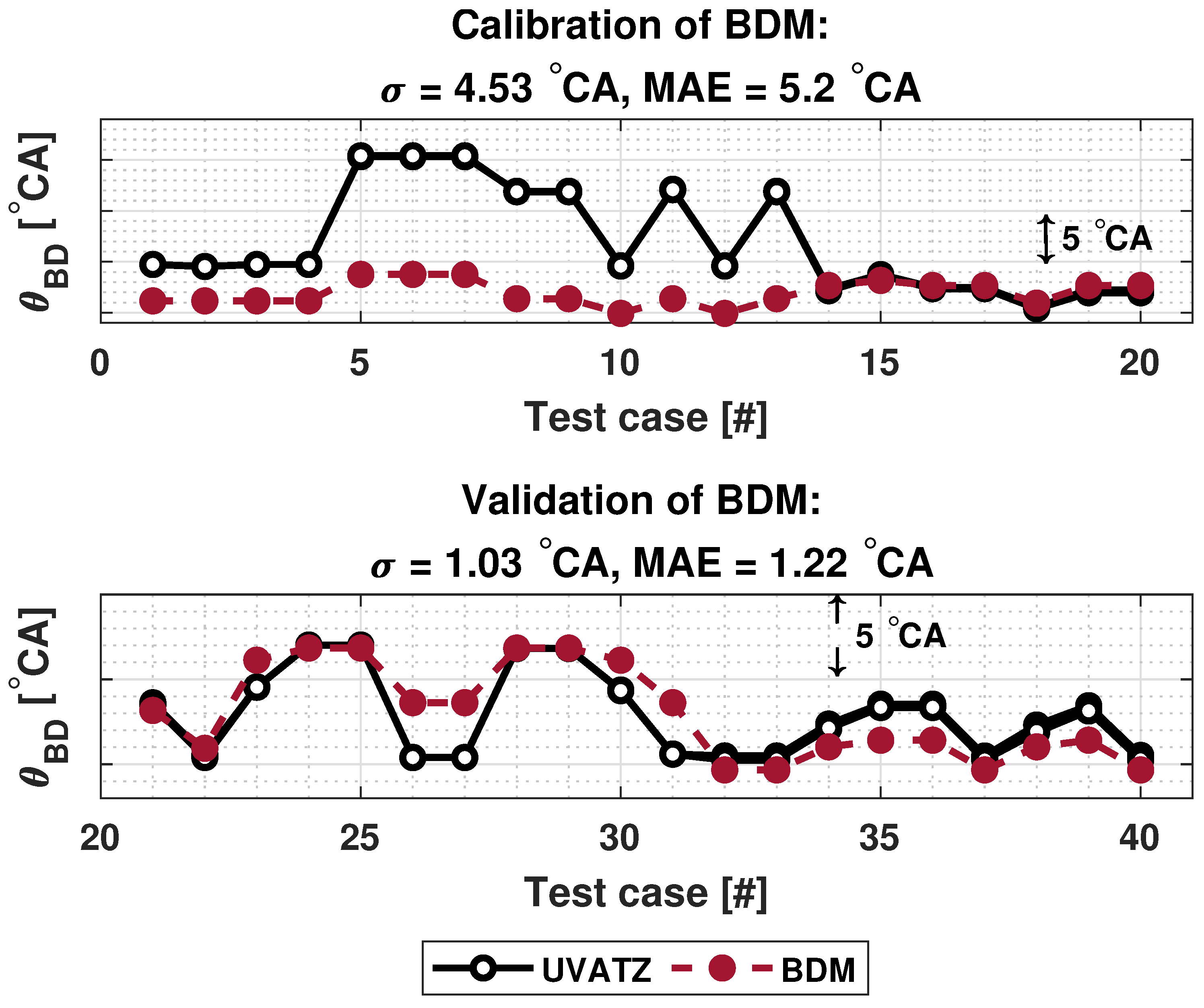
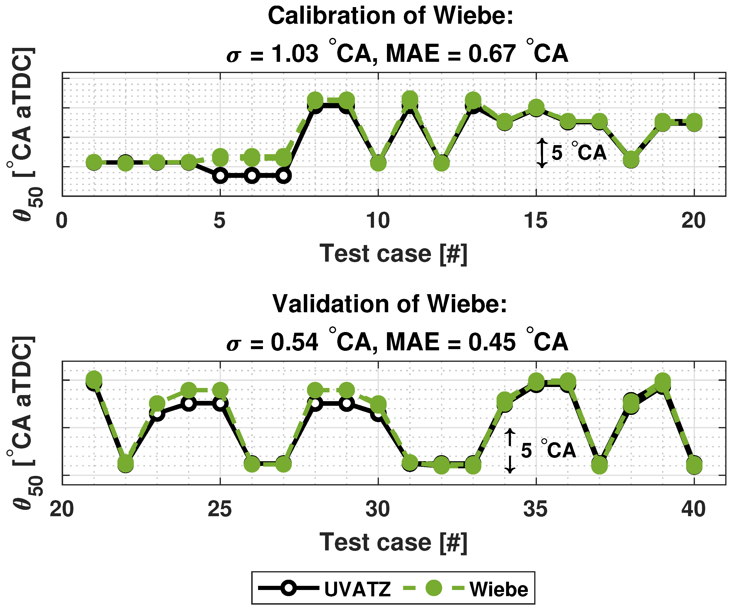
Section 3.1 presents the results for parametrization of the COM and 
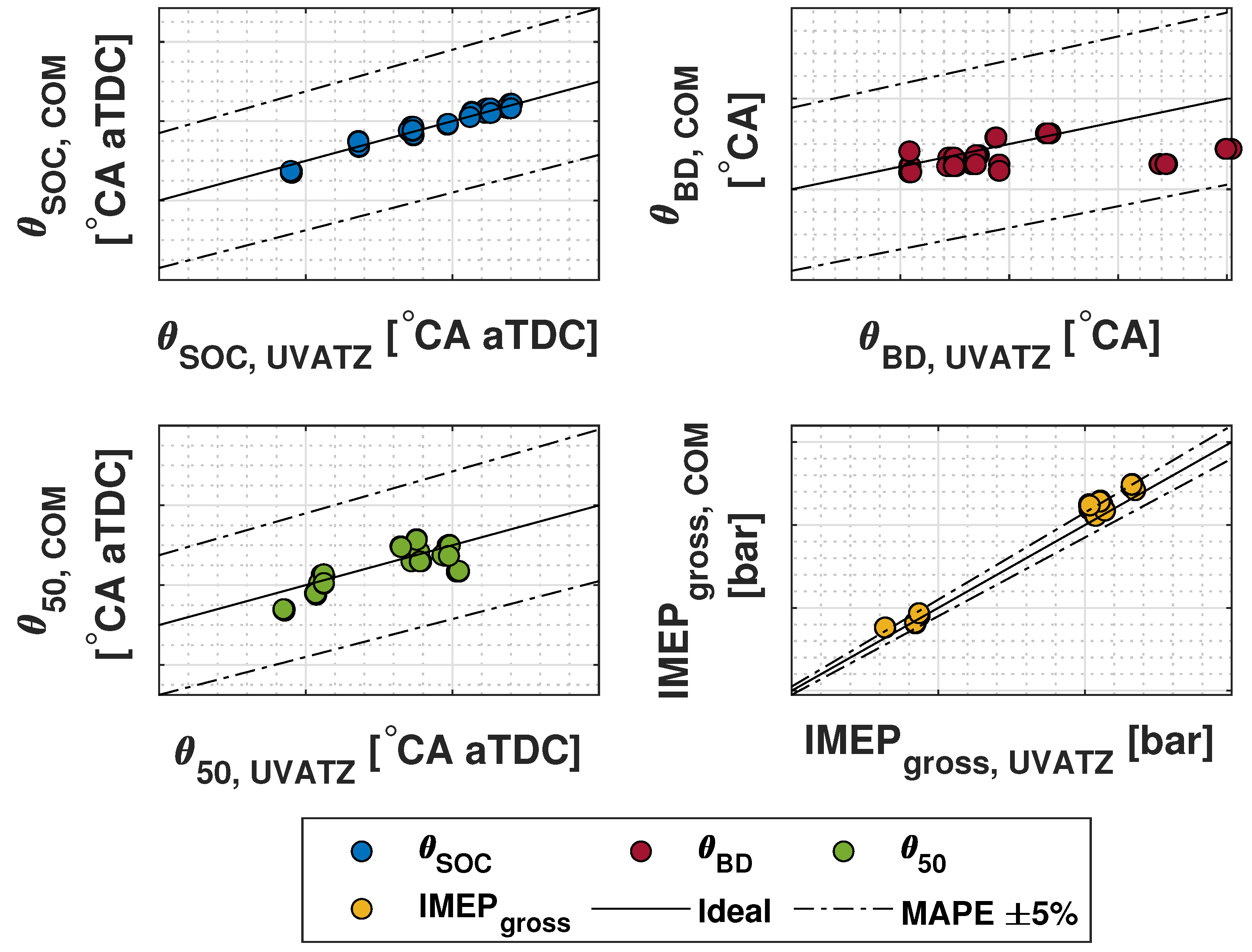
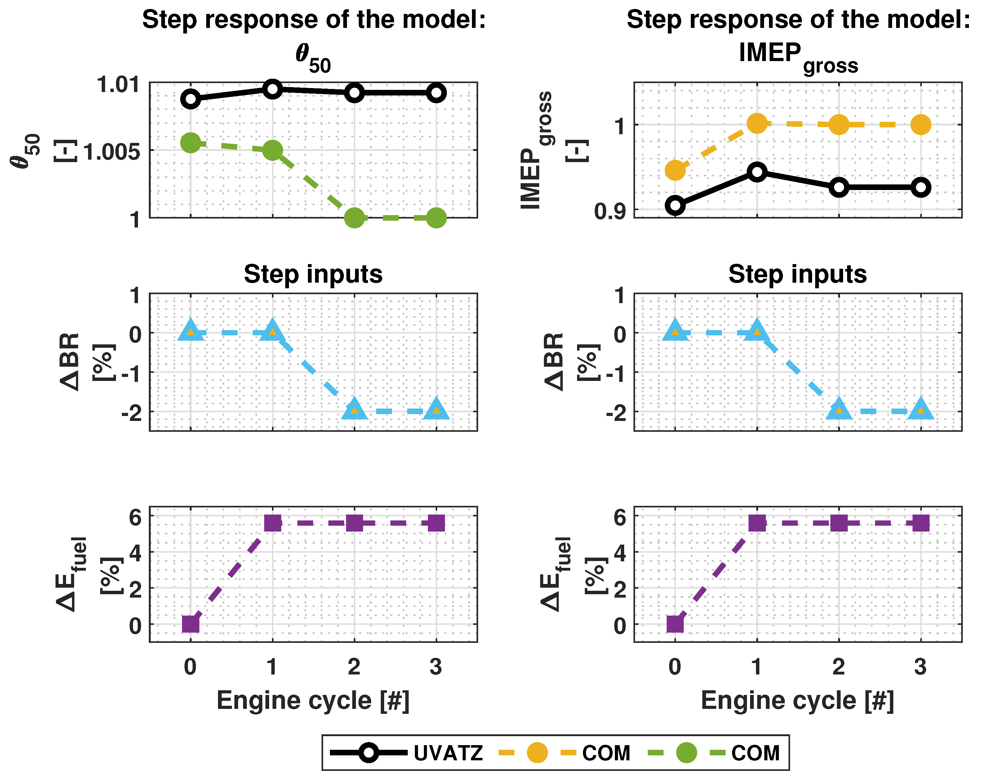
Section 3.2 presents the validation results of COM compared to UVATZ. Simulation results of the standalone COM and the closed-loop system are presented and discussed in Section 3.3 and Section 3.4, respectively. Finally, Section 4 and Section 5 summarize the next steps of the current research.
2. Materials and Methods
The control-oriented model implemented in this work is based on a high-order physics-based model called University of Vaasa Advanced Thermokinetic Multizone Model (UVATZ), developed by Vasudev et al. [25,27]. The model is capable of capturing the effects of fuel injection and mixture, in-cylinder mass and heat flow, heat-loss to the cylinder wall and heat release profile utilizing chemical kinetics mechanism presented in [28]. Model validation in earlier works on the same engine revealed 5% relative error for all combustion performance indicators, which are gross indicated mean effective pressure (), , crank angle at 10% () and 50% () energy released and net heat release. Complete details regarding the implementation and validation of the UVATZ model can be found in [25].
The nonlinear COM is a phenomenological, physics-based model capable of predicting main performance indicators of RCCI combustion in both crank angle and cycle domain. The RTM is a physics-based LPV-model used for MPC design. Both the nonlinear RCCI COM and RTM are calibrated and validated against the UVATZ model. The details of COM and designed closed-loop system are presented in the following subsections.
2.1. Nonlinear RCCI Control-Oriented Model
The nonlinear RCCI COM implemented in this work consists of submodels presented in this section. The main structure and majority of the submodels are based on [12,13] with an exception of calculating in-cylinder temperature, pressure and subsequently the IMEP [29,30,31]. The flowchart of the developed RCCI COM is presented in Figure 1. Each submodel is presented in the following subsections.
Figure 1.
Flowchart of the developed RCCI control-oriented combustion model for predicting main combustion indicators.
2.1.1. Modified Knock Integrated Kinetics Model
The modified knock integral model (MKIM) is a modified version of the Livengood and Wu knock integral model (KIM) [32], originally developed to predict auto-ignition in spark ignition (SI) engines. Shahbakhti [33] modified the correlation to predict auto-ignition for HCCI combustion. The model was eventually modified towards RCCI combustion by Sadabadi et al. [13], which is presented in Equation (1). The original KIM was adjusted towards RCCI based on polytropic compression, fuel concentration, premixed ratio and diesel injection timing. The first integral in Equation (1) describes the compression of LRF entering the combustion chamber and mixing with air from to and the second integral describes the compression of the mixture of HRF and LRF from to leading to the auto-ignition. The start of combustion occurs when the integral approaches unity.
In Equation (1), and are tuning coefficients, such that the condition of the equation holds. The denominator of the second integral () is the ignition delay () corresponding to the mixture of air with both LRF and HRF. Additionally, N denotes the engine speed, is the equivalence ratio of HRF and LRF, and are pressure and temperature at IVC, is the polytropic coefficient, describes the reactivity of the fuel blend and is the ratio of volume at IVC () to the volume at any crank angle (). and are defined in Equations (2) and (3), respectively.
In Equation (2), is the stoichiometric fuel-air-ratio and CN is cetane numbers of the fuels. In this work value of was kept constant, which is same as for the UVATZ model. The selection is based on the criterion of matching net heat released. The values of and are based on surrogate fuels in the UVATZ model. More details about the model and its formulation can be found in [13].
2.1.2. Burn Duration Model
According to [34], the primary mechanism in RCCI combustion involves the formation and propagation of ignition pockets within the charge. This enables the utilization of spontaneous ignition front speed () for estimating the burn duration (). Sadabadi et al. [13] formulated a correlation between burn duration and as follows
where and are tuning coefficients. Here, is defined as
According to Equation (5), the subsonic spontaneous ignition front speed is dependent on the gradient of the ignition delay [35]. The ignition delay gradient of the mixture does not solely rely on the initial state; it is influenced by the extent of compression heating during combustion as well. This heating, in turn, hinges on the initial distribution of the mixture conditions [35]. As Equation (5) indicates, the is a function of the gradient of the ignition delay. It should be noted that the gradient of can be considered in terms of one or several variables highlighted in Equation (1). The study of [36] included all of the variables in the gradient of ignition delay. In [13] ignition front speed is estimated based on the changes of the equivalence ratio. According to their study, the gradient of ignition delay is attributed to the stratification of equivalence ratio. Their formulation of in Equation (5) for an RCCI engine is as follows:
where the ignition delay () is indeed defined as the denominator of the second integral in Equation (1) and is the gradient of equivalence ratio at the start of combustion. In this work, variations in the injected fuel mass are considered as the source of the gradient in . Sadabadi et al. [13] employed the following assumptions to establish the gradient of the equivalence ratio within the charge:
- The gradient of equivalence ratio remains uniform with respect to the radial distance from the cylinder’s centerline, particularly from the injection point. The highest diesel equivalence ratio is typically observed in close proximity to the cylinder liner and diminishes steadily as the radial distance towards the cylinder centerline increases [34]. This assumption leads to a simplified one-dimensional distribution of equivalence ratio across the mixture.
- Estimating the maximum equivalence ratio involves considering the mixing degree of diesel fuel, which is contingent on the ignition delay. Given that the start of combustion has been previously estimated using Equation (1), the apparent ignition delay () in crank angle degrees (CAD) is computed as shown in Equation (7).
Given the apparent ignition delay, estimating the maximum equivalence ratio value for HRF () that aligns with the maximum value of equivalence ratio within the mixture is accomplished by:
Here, , and are tuning coefficients. The derivative of with respect to arises from the linear spatial distribution of the diesel fuel. Therefore, based on the previously mentioned assumption that mixture is most reactive in the proximity of the cylinder liner and decreases closer to the cylinder centerline reaching the value of zero, the gradient in equivalence ratio at the start of combustion () is
Once in Equation (4) has been obtained, it is possible to calculate the end of the combustion ()
In this work Equation (4) is also referred to as burn duration model (BDM). More details about the BDM and its formulation can be found in [13].
2.1.3. Wiebe
Single Wiebe function, as presented in Equation (11), is used to calculate a mass fraction burned () and subsequently to obtain combustion phasing () once and are known [30]
Here, A and B are tuning coefficients, is the crank angle range, and are previously obtained angle at the SOC and combustion duration, respectively. Subsequently, the cumulative heat release (CHR) is obtained from Equation (12)
where is the total energy released from both fuels and is the combustion efficiency.
2.1.4. In-Cylinder Pressure Reproduction and Post-Processing
The in-cylinder pressure () model is formulated from the first law of thermodynamics by neglecting the loss mechanism and assuming the content of the cylinder as ideal gas with constant specific heats [31]. The compression is assumed to be polytropic. Thus, enabling the utilization of Equation (13) to estimated in-cylinder pressure at
The model presented in Equation (14) is used estimate in-cylinder pressure rate during the combustion phase.
Similarly, the expansion phase can be assumed as polytropic, enabling the estimation of in-cylinder pressure at EVO
In Equations (13)–(15) is the heat release rate (HRR) and is the polytropic coefficient independent of temperature which is already described along with its selection criterion in Section 2.1.1. In this paper and CHR as well as and HRR are used interchangeably.
The in-cylinder temperature () is obtained from the ideal gas equation using the conditions at IVC [29]:
Indicated mean effective pressure describes the work delivered to the piston per cycle per unit displaced volume () [30]:
In this work, Equation (17) is used to estimate , which covers the closed cycle from to . Performance metrics, including and the Crank Angle corresponding to X% Mass Burned (CAX), are derived through the post-processing of pressure signals.
2.2. RTM and Model Predictive Control Design
Nowadays, optimality is a matter of great importance for controllers. Model predictive control is one of the most applied optimal control approaches; it has the capability of taking the constraints into consideration. In addition to effectively manage system delays, its robustness is ensured due to the implementation of a receding horizon. Although, nonlinear MPC seems more accurate, it entails huge computational burden (up to 40 times, compared to the linear one [37]) to solve the nonlinear optimization problem. This could easily cause the control system not to be real-time. Linear MPC, on the other hand, has much lighter computational load and can be operated in real-time [38]. More importantly, as shown in [37], there could be only less than 2% difference between the accuracy of linear MPC and nonlinear MPC. For these reasons, linear MPC has been employed in this study.
Predictive models inherently carry uncertainty, and failure to consider this uncertainty in control design can result in instability. It should be noted that the system properties vary notably in different operating points. Adaptive MPC strategy is one feasible approach with adapting prediction model for changing conditions. It can also upgrade the prediction accuracy and controller performance of the strongly nonlinear plant. An adaptive MPC with the linear parameter varying RTM model is developed for controlling the RCCI COM. RTM is capable of estimating heat release, heat release rate, in-cylinder pressure, combustion phase and start of combustion. The RTM estimates the aforementioned variables both crank angle and cycle-wise and updates the internal plant model used by the MPC controller in real-time for each operating point [14].
In this work a centralized MIMO MPC is developed to control and of the COM. The chosen controller signals (U) are total fuel energy () and energy-based LRF-HRF BR as presented in Equation (18)
where m is the injected fuel mass, and LHV is the lower heating value of LRF and HRF, respectively. The RTM is defined as:
Here k indicates the cycles. The updated values of , and for cycle are defined as the sum their respective values at cycle k and the changes imposed by the control variables of Equation (18). As previously mentioned, RTM can estimate its variables in crank angle domain as well. Thus, , are also vectors covering the closed cycle of the RCCI combustion. and represent process uncertainties as and mass of EGR (), since these variables cannot be imposed as control inputs. These disturbances are modelled as zero-mean Gaussian noise. The linear relation between the control signals and CHR, and is shown in Equation (20).
This linear relation is based on [29] and was adapted for RCCI combustion by Storm et al. [14]. HRR and in-cylinder pressure are obtained from CHR according to the first law of thermodynamics similarly as in Equations (12) and (14). Equation (20) describes the changes of and BR affecting , and . Additionally, incorporation of coefficients and are due to the fact that and could be negative or positive. Therefore, and are tuned such that are are changed accordingly. The matrix B in Equation (19) is calculated numerically according to the linear relation. Details on the linearization of RCCI combustion model, i.e., expanded form of Equation (20) can be found in [14].
As previously explained in Section 2, is defined as crank angle at 50% of energy released. Therefore, is obtained from . The system states (X) are and outputs (Y) are . The control variables are changes of and BR fed to the process, not their respective absolute values. Thus, a control signal is presented as .
The control problem is formulated as linear quadratic optimization problem with the following cost function.
where is the reference output vector over prediction horizon, Q and R are weights on the reference tracking and control variables, respectively. The optimal control within the optimization window is presented as
where and are the constraints on the control variable incremental variation, and and are the output constraints.
The entire model-in-loop (MiL) framework is implemented in Simulink environment with embedded Matlab functions. The schematics of the adaptive MPC system is presented in Figure 2 and parameter values of the MPC are presented in Table 1. The adaptive MPC uses and to control outputs and of the nonlinear RCCI combustion model previously described in Section 2.1. The controlled outputs along with other main outputs, i.e., , , and BR, control signals and states are connected back to the RTM, which updates the predictive model of the MPC based on the current operating condition for the next cycle. The values of the MPC in Table 1 are chosen to achieve the best performance and low steady state error.
Figure 2.
Schematics of the designed system.
Table 1.
Adaptive MPC parameter values.
2.3. Experimental Setup
The current study is based on the same engine platform as in [25]. Thus, this provides the possibility to use UVATZ to explore the design space. As outlined in [27], multizone models possess the capability to attain the accuracy and predictivity of computational fluid dynamics (CFD) models. This is achieved with computational times in the order of seconds, maintaining a 5% error margin compared to experimental data.
The experimental data, which are used for calibrating and validating the UVATZ, are generated from a Wärtsilä “Mono” single-cylinder research engine (SCRE). This engine is a variant of the commercial multi-cylinder, dual-fuel, two-staged turbocharged W31 engine [39]. The SCRE operates in RCCI mode using natural gas (NG) as LRF and light fuel oil (LFO) as HRF. NG is controlled via a multipoint upstream of the intake valve and LFO is directly injected via a twin-needle injector [40]. The specifications of the engine are presented in Table 2.
Table 2.
Specifications of the Wärtsilä single-cylinder research engine (SCRE).
The measurements obtained from the SCRE contain six steady state operating conditions, which are used as baseline conditions for the research. These operating conditions are indicated as A to F in Table 3. The data is presented with respect to “Ref”, which corresponds to an IMO TIER III 25% load calibration point of the W31DF engine. The blend ratio of LRF and HRF is defined using NG on an energy basis as described in Equation (18). The remaining parameters in the table are air-to-fuel ratio () and the injection timing of the HRF ().
Table 3.
Steady state measurement data. The baseline “Ref” is the standard IMO TIER III 25% load calibration point on the commercial W31DF [42].
Due its accuracy and predictive nature in multiple operating conditions, the UVATZ model is used to generate calibration and validation data for the nonlinear RCCI model. This approach allows for the generation of quasi-transient data, which are based on the assumption that inputs to UVATZ vary linearly between the steady state measurement points. It must be emphasized that the original experimental data of the W31DF engine presented in Table 3 lack transient conditions.
The reference data are synthetically generated utilizing mixed-factorial design. Unlike full factorial design, mixed-factorial does not incorporate all of the factor interaction, which reduces the size of the dataset and costs, especially with high number of factors [43]. In this work, the levels in the design represents the operating conditions and factors are the inputs that have been altered for each test run. The factors and their respective levels are highlighted in Table 4. In this work, operating conditions indicated by A, B and E in Table 3 are chosen for mixed-factorial design. The factors chosen for the data generation are , , , BR and , which are considered to be most influential to the COM. Three levels were chosen for , , and BR, and two levels for and . The test cases contain both nominal (steady state) and transient conditions. The total number of performed test runs are 54 with each test case consisting of eight cycles. Some of the test cases contain abnormal behaviour, which are observed as high value of . Additionally, it took 2–3 cycles for the UVATZ model to converge. Thus, only last the six cycles were included in the final dataset. After excluding the abnormal test cases, the final number of cases were reduced to 40.
Table 4.
Mixed-factorial design.
The dataset is used for parameterization of COM, holistic full cycle simulations of COM and closed-loop system. Since the utilized dataset is based on a commercial engine measurements and thus confidential, the absolute numerical results in this paper are either normalized, scaled or otherwise hidden.
3. Results
3.1. Parameterization of the Nonlinear RCCI COM
The first half of the dataset presented in Table 4 was used for calibrating and the second half for validating MKIM, Wiebe and burn duration models described in the previous section. To be more specific, the calibration dateset was used to tune the coefficients presented in Equations (1), (4), (9) and (11). Figure 3 presents the parametrization results of MKIM. Here has been chosen as . The model achieves a mean absolute error (MAE) below 0.7 °CA for all cases as well as a good trendwise accuracy as indicated by the standard deviation of MAE ().
Figure 3.
Results of parametrization of MKIM.
The BDM was calibrated by choosing crank angle at 80% energy released () as the . In most applications crank angle at 90% energy released () is chosen to indicate the end of combustion. However, is often difficult to estimate. Additionally, based on observations on the results of mixed-factorial design, the results of estimated by the UVATZ had less deviation compared to . The parametrization of BDM has higher absolute error in the first 13 test cases of the calibration data, as shown in Figure 4. However, the trendwise accuracy is good, although it is not well observable from the figure. The overall validation results are feasible with a MAE below 1.5 °CA. It is worth mentioning that calibration or validation error outside of 1–2 °CA threshold is still acceptable and corresponds to real-world applications. In addition to that, high calibration MAE of BDM might be due to the model’s sensitivity to those particular test cases.
Figure 4.
Results of parametrization of burn duration model.
Figure 5 presents the calibration and validation results of the Wiebe function. achieves a MAE of below 1 °CA for both calibration and validation data in addition to its trendwise accuracy.
Figure 5.
Results of parametrization of Wiebe.
3.2. Full Cycle Validation of the Nonlinear RCCI COM
After parametrization of the MKIM, Wiebe and BDM, the RCCI COM was simulated to further validate its coupled submodels and the remaining combustion indicators, i.e., against the UVATZ model for full engine cycle, which was presented earlier in Figure 1.
Despite the simplicity of the single Wiebe, the COM achieved a feasible accuracy for CHR, HRR, in-cylinder pressure and temperature. Figure 6 presents normalized values of the estimated aforementioned variables for a mid load operating point.
Figure 6.
Normalized values of estimated , , and .
The overall estimation accuracy of the nonlinear RCCI COM after all of the submodels have been coupled together is presented in Figure 7 and Table 5, respectively. The mean absolute percentage error (MAPE) value for and is quite low as one could have anticipated from the calibration and validation results. The MAPE of is slightly higher due to the high calibration error. While the MAPE of falls within the range, its relatively higher value compared to other combustion indicators can be attributed to the simplification in estimating and . As shown in Figure 6, estimated by COM has both a lower trendwise and absolute accuracy after . That on the other hand affects the estimation of in-cylinder pressure and subsequently the estimation of .
Figure 7.
Overall estimation accuracy of the developed nonlinear RCCI COM for main combustion indicators.
Table 5.
Overall validation results of RCCI COM.
3.3. Standalone Nonlinear RCCI COM Simulations
In this section, the reactions of both the nonlinear RCCI COM and the UVATZ models to step changes of and BR are analysed. The simulations were carried out in MATLAB’s Simulink R2023b software. The sampling time of the simulation was set to 1 s and the total number of cycles to 3.
The absolute value between the variables is within the same range of MAE as obtained during the parametrization of the COM. The values of and are scaled with respect to converged results of COM. Step changes are applied during the first cycle for and the second cycle for , respectively. The step response of both models for one test case are shown in Figure 8. The mean absolute error of and are 2.4 °CA and 0.57 bar, respectively. Due to the scaling, it is difficult to observe the system’s dynamics. of COM decreases after step change of , while of UVATZ slightly increases. Decrease of causes of both models to decrease. The increase in increases of both models, and the decrease of decreases , although it is particularly small in case COM. Overall, it can be observed that is proportional to , while is proportional to and inversely proportional to .
Figure 8.
Comparison of step responses of the UVATZ and COM, when changes are applied on variables and . The absolute values are scaled.
The mean absolute percentage error of the entire simulations has been presented in Figure 9. The MAPE of is below the threshold of 5% for 29 test cases. The high error in the remaining 11 test cases stems from the fact that the UVATZ model produced results that indicated misfire. This would have otherwise resulted in an accuracy similar to that shown previously in Figure 7. Based on the step responses, it can be concluded that the COM is capable of capturing a similar predictivity and dynamics as the UVATZ model. Thus, the COM can be used for closed-loop simulations.
Figure 9.
The mean absolute percentage error between the UVATZ and COM models for the standalone simulations.
3.4. Closed-Loop Control Simulations
The closed-loop system was simulated in steady state and transient cases for both mid and high engine load. The control signals were the same as in the previous simulations, i.e., and and process outputs were and . The sampling time was set to 80 ms, corresponding to one engine cycle at the speed of 750 RPM. Figure 10 and Figure 11 present the results with constant and step inputs in nominal operating conditions.
Figure 10.
Simulation results of the system for and control using and as control variables at nominal mid and high engine loads. No step change has been applied on the reference values. (a) Steady state results at mid engine load. (b) Steady state results at high engine load.
Figure 11.
Simulation results of the system for and control using and as control variables at nominal mid and high engine loads. A small step change has been applied on the reference values. (a) Step response of the system at mid engine load. (b) Step response of the system at high engine load.
In the nominal conditions, the convergence of towards the reference value is slow. However, the steady state error remains small. As shown in Figure 10a, the maximum steady state error is 1.1 bar. However, decreases rapidly during the first 50 cycles, after which the error is below 0.5 bar. In Figure 10b the steady state error of remains below 0.5 bar in high load condition, although it never reaches the reference value. In both cases reaches the reference values in relatively short time.
Figure 11a,b present the nominal mid and high load conditions with step inputs. is changed by 2 °CA and by 0.5 bar. In both cases, accurately follows the reference value. fully reaches the reference value after the step change is activated. Similar behavior between the inputs and outputs can be observed as previously shown in Section 3.3. At the 50th cycle, the step change for takes place. This can be seen as an increase of , which decreases the . Similarly, with decreasing increases as can be seen at the 100th cycle. This behavior could be explained by the fact that imposes BR as shown in Equation (18).
In the transient case, the nominal condition of the system is changed from mid load to high load, as shown in Figure 12. Here, both output signals showcase a good absolute and trendwise accuracy. The peak of does not seem to affect the during the step change. This might be due to a high value of , which overcomes the affect of . Additionally, achieved its maximum value during the transition. Increasing or decreasing the maximum constraint of would be seen as overshoot or undershoot of , respectively.
Figure 12.
Simulation results of the system for and control using and as control variables during transient from mid to high engine load.
The nominal operating conditions with step inputs and their transient were performed again with small disturbance added to the process inputs and . The disturbances were added as random noise. The mean () and standard deviation () for each input disturbance are presented in Table 6.
Table 6.
Mean and standard deviation of added process disturbance.
Despite the process disturbance, the system remains stable, as shown in Figure 13 and Figure 14. During the nominal operating conditions the fluctuation of and stay between ±1 °CA and bar respectively, which is well within their operating boundaries. However, the fluctuation of the control signal becomes high making it difficult to distinguish the control reactions as was shown in previous test cases. Similar behavior can be observed in the transient case as show in Figure 14. The major difference in these results are the decline of fluctuation in control signals during high load. Same phenomenon is observable in the outputs. The fluctuation of stays between ±1 °CA during mid engine load and between ±0.1 °CA during high engine load. stays within bar during the mid engine load and reaches its reference value during high engine load.
Figure 13.
Simulation results of the system with process disturbance for and control using and as control variables at nominal mid and high engine loads. (a) Step response of the system at mid engine load. (b) Step response of the system at high engine load.
Figure 14.
Simulation results of the system with process disturbance for and control using and as control variables during transient from mid to high engine load.
The overall tracking errors of the controlled variables in terms of MAE and MAPE are shown in Table 7. maintains a low tracking error for all cases. The errors are slightly higher in cases with process disturbances as one could anticipate. However, the MAE stays below 1 °CA. has higher errors, which can be explained with long settling time, especially in the nominal conditions. Despite this, MAE stays below 0.5 bar. Both output signals achieve the MAPE below 5%.
Table 7.
Tracking errors of and .
4. Discussion
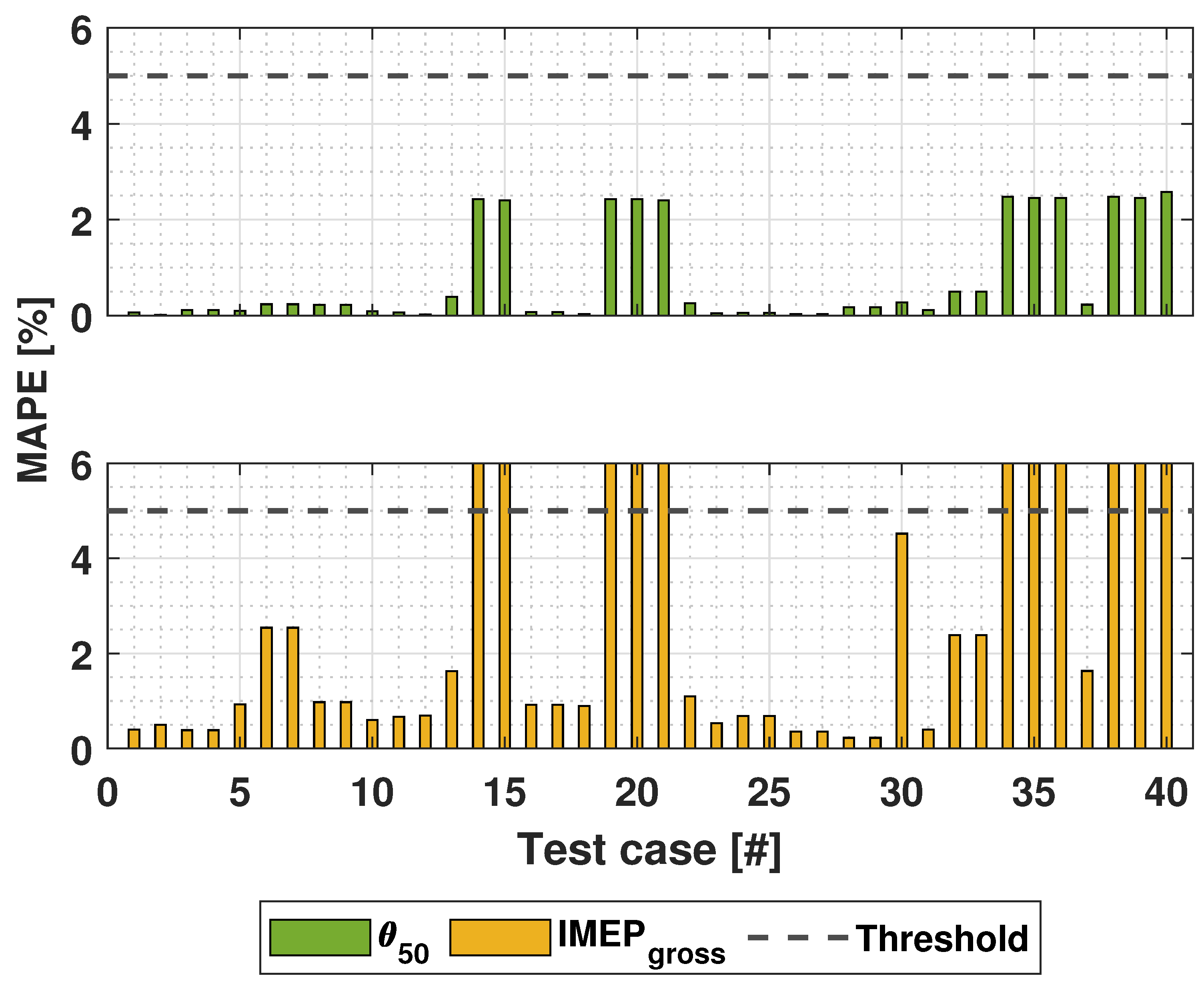
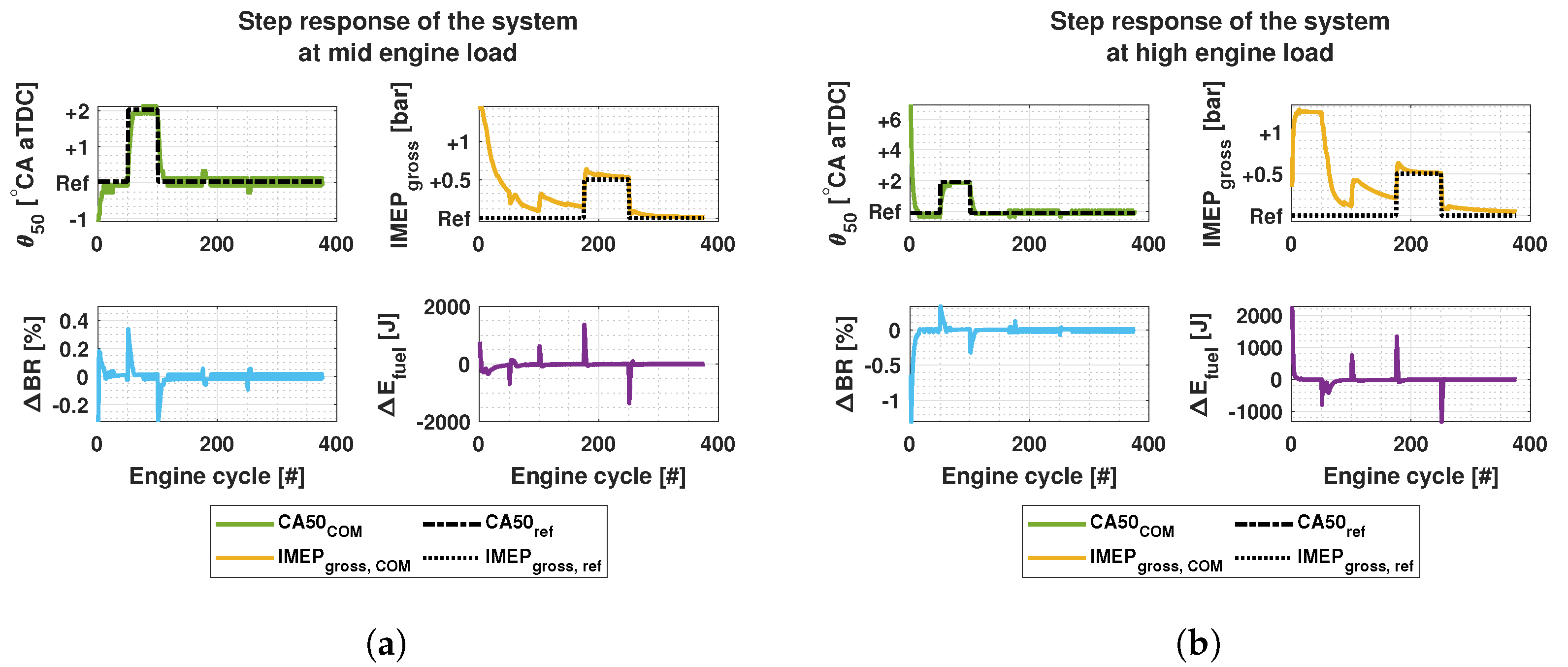
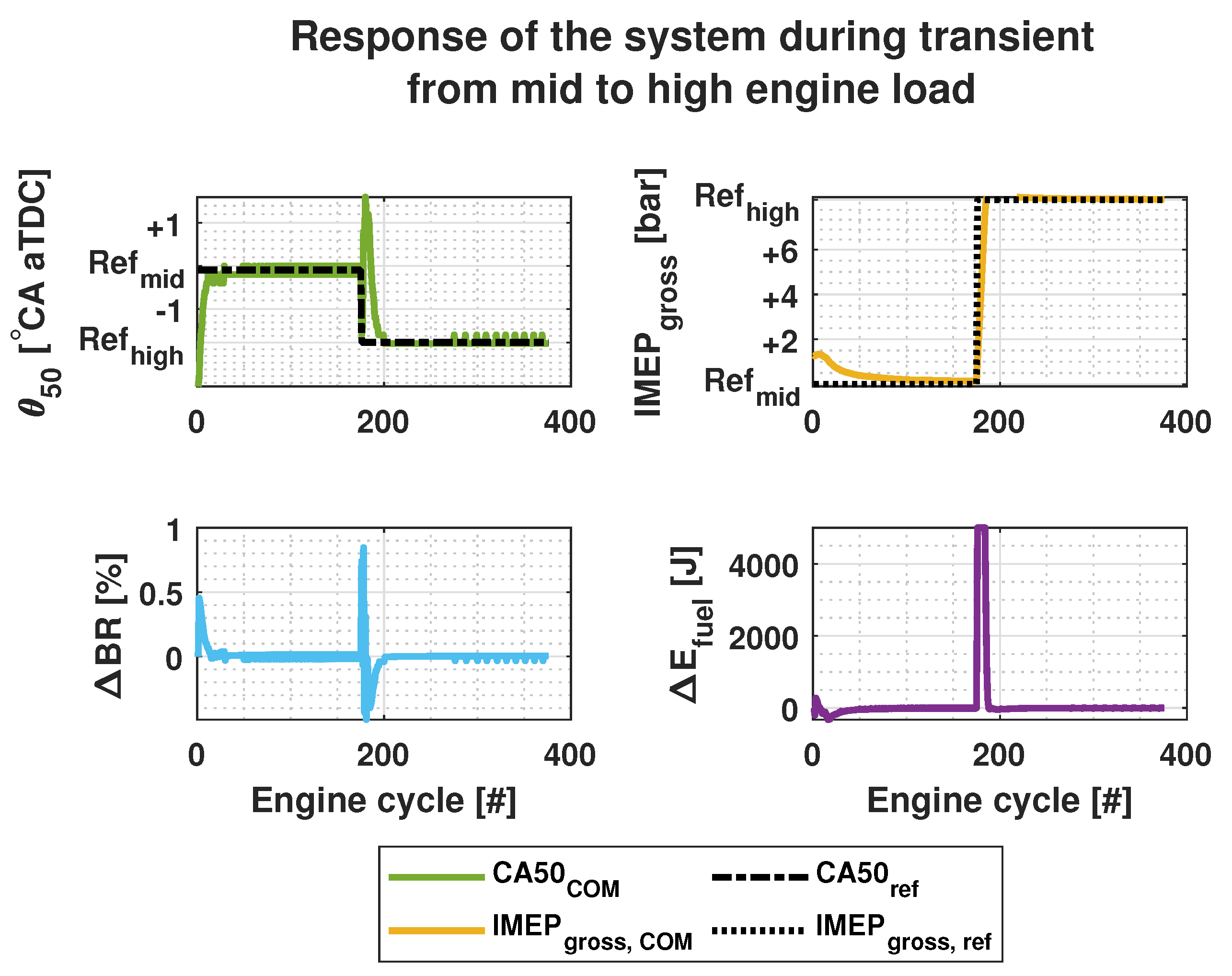
The results indicate a feasible performance of the developed system. The nonlinear RCCI COM achieved the simulation time in order of milliseconds, which was faster than the original target. Additionally, it achieved an accuracy within the target 5% limit compared to the UVATZ model. The model-based control system provided feasible results in both nominal and transient conditions with low tracking errors within the target 5% limit.
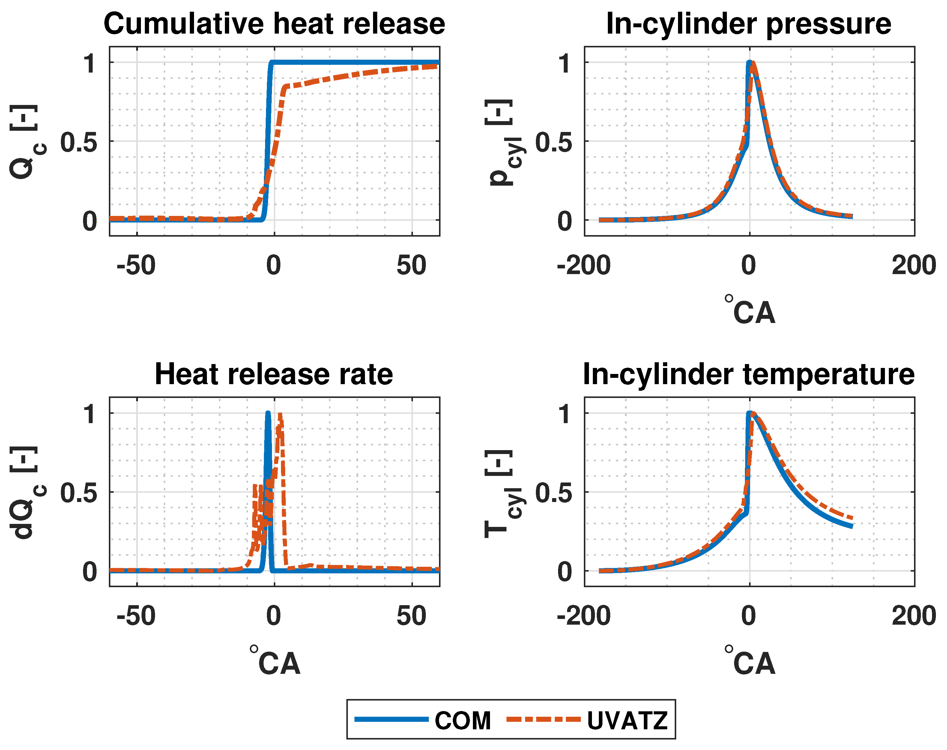
In certain operating conditions, the COM did not achieve the desired absolute accuracy despite a good trendwise accuracy. This might be due to the utilization of a single Wiebe function for estimating CHR, HRR and . was well estimated as shown in results, but and do not achieve the same level of accuracy as previously discussed in Section 3.2. One contributing factor to this discrepancy, in addition to the simplicity of the Wiebe function, is the value of the efficiency factor. The UVATZ model calculates the combustion efficiency for each cycle, but in COM the efficiency is set to a fixed value. The UVATZ model solves the detailed chemical kinetics of its zones to maintain its predictive nature. The in-cylinder fuel and thermal stratification govern the order of zonal ignitions. For this reason the HRR is a superposition of heat released in each zone causing the "spiky" signal, which does not correspond to a real-world experimental results. However, the integration of the HRR of UVATZ results in an accurate CHR. Nevertheless, it can be assumed that single Wiebe is not able to fully capture HRR of the UVATZ, and since HRR is used in the in-cylinder pressure model, its affect can be seen as low estimation accuracy of and subsequently in-cylinder temperature and . It is worth mentioning that in this work the Wiebe function was primarily optimized for estimating . Therefore, low accuracy in the CHR and HRR trends were expected. Despite these limitations, the controller is able to achieve feasible accuracy for as well for all the test cases.
The developed model-based control system shall be further improved and expanded based on the following propositions:
- Expanding the operational range of the nonlinear RCCI COM. This means further optimization of the model.
- Multiple Wiebe could improve the CHR and HRR estimations and subsequently improve the in-cylinder pressure and IMEP estimations without increasing the computation time.
- Expanding the COM with physics-based emission models. This provides the possibility to analyze the correlation between the main combustion performance indicators, especially , and , and , and UHC.
- Incorporating , and in the control design as constraints to maintain desired performance and emission levels.
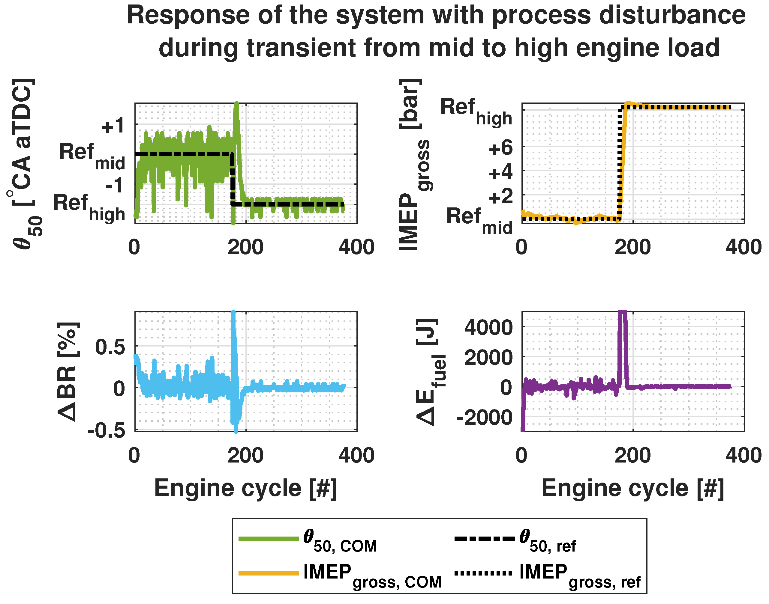
- Further investigation of the controller’s performance in the presence of disturbances.
- Applying multi-injection functionality to further improve the efficiency of the combustion.
- Expanding the nonlinear RCCI COM with a mean value airpath model provides the possibility to control the variables at IVC, to which the RCCI process is highly sensitive.
5. Conclusions
In this work, a cycle-to-cycle model-based control system was developed for dual-fuel marine engines operating in RCCI mode. The control-oriented model was calibrated against the Wärtsilä’s W31DF engine for steady state operating conditions. Transient conditions were generated with an state-of-the-art fully predictive thermo-kinetic multizone model. The work makes the following conclusions:
- A sparse experimental dataset was augmented by using a higher fidelity combustion model to generate a broad dataset of clean sweeps and transient simulations.
- The developed physics-based dynamic nonlinear RCCI COM achieved a feasible absolute and trendwise accuracy in terms of main combustion performance indicators within a 5% error margin target compared to the detailed UVATZ model.
- A novel LPV-model was coupled with an adaptive MPC to control the COM. and were controlled with and . A tracking error within a 5% error margin target was achieved regardless the additive model uncertainties for nominal mid and high engine load operating conditions and their transient.
- achieved the reference value much faster than the . However, despite this, the steady state error remained low.
The current stage of the developed control system establishes solid foundations for adopting RCCI combustion in commercial marine engines. The results showcased a feasible accuracy with real-time simulation capabilities, which further advances a model-based framework towards experimental testings.
Author Contributions
Conceptualization, methodology, development of COM, simulations, writing—original draft preparation, A.M.; Development of RTM, methodology, X.S.; Implementation of adaptive MPC, A.-M.S.; Development of UVATZ, methodology, A.V.; Advising and supervising the paper and methodologies, K.Z.; Consulting on methodologies and modeling, providing the experimental data, J.H.; Advising, supervision, project administration, M.M. All authors have read and agreed to the published version of the manuscript.
Funding
This work was conducted in framework of Clean Propulsion Technologies with financial support from Business Finland (ref. 43918/31/2020).
Institutional Review Board Statement
Not applicable.
Informed Consent Statement
Not applicable.
Data Availability Statement
The datasets presented in this article are not readily available due to commercial restrictions.
Conflicts of Interest
The authors declare no conflict of interest.
Abbreviations
The following abbreviations are used in this manuscript:
| BD | Burn duration |
| BDM | Burn duration model |
| BR | Blend ratio |
| BTE | Brake thermal efficiency |
| CA | Crank angle |
| CAD | Crank angle degree |
| CAX | Crank angle corresponding to X% energy released |
| CC | Combustion centroid |
| CFD | Computational fluid dynamics |
| CHR | Cumulative heat release |
| CN | Cetane number |
| CO | Carbon monoxide |
| CO2 | Carbon dioxide |
| COM | Control-oriented model |
| EGR | Exhaust gas recirculation |
| EOC | End of combustion |
| EU | European union |
| EVO | Exhaust valve opening |
| FAR | Fuel-air-ratio |
| HC | Hydrocarbons |
| HCCI | Homogenous charged compression ignition |
| HRF | High reactivity fuel |
| HRR | Heat release rate |
| ID | Ignition delay |
| IMEP | Indicated mean effective pressure |
| IMO | International maritime organization |
| IVC | Inlet valve closing |
| KIM | Knock integral model |
| LFO | Light fuel oil |
| LHV | Lower heating value |
| LPV | Linear parameter-varying |
| LRF | Low reactivity fuel |
| LQI | Linear-quadratic-integrator |
| LTC | Low temperature combustion |
| MAE | Mean absolute error |
| MAPE | Mean absolute percentage error |
| MiL | Model-in-loop |
| MIMO | Multi-input and multiple-output |
| MKIM | Modified knock integral model |
| MPC | Model predictive control |
| MZM | Multizone model |
| NG | Natural gas |
| NOx | Nitrogen oxides |
| PCCI | Premixed charged compression ignition |
| PM | Particulate matter |
| PPC | Partially premixed combustion |
| PRR | Pressure rise rate |
| RCCI | Reactivity controlled compression ignition |
| RTM | Real-time model |
| SCRE | Single cylinder research engine |
| Sulphur dioxide | |
| SOC | Start of combustion |
| SOI | Start of injection |
| SVM | Support vector machine |
| UHC | Unburned hydrocarbons |
| UVATZ | University of Vaasa advanced thermokinetic multizone model |
| VGT | Variable geometry turbocharger |
List of Symbols
The following symbols are used in this manuscript:
| Total fuel energy | |
| J | Cost function |
| k | kth cycle |
| N | Engine speed |
| Total number of cycles | |
| Polytropic coefficient | |
| Mass of EGR | |
| Mass of HRF | |
| Mass of LRF | |
| p | Pressure |
| Q | Weight of the reference tracking |
| Cumulative heat release | |
| Total energy released | |
| R | Weight of the control variable |
| Spontaneous ignition front speed | |
| T | Temperature |
| U | Control variable |
| u | Constraints of the control variables |
| V | Volume |
| Ratio of volume at IVC to the volume at any crank angle | |
| Displacement volume | |
| X | System states |
| Mass fraction burned | |
| Y | System outputs |
| y | Output constraints |
| Combustion efficiency | |
| Crank angle | |
| Air-fuel-ratio | |
| Mean of Gaussian random noise | |
| Standard deviation | |
| Ignition delay | |
| Equivalence ratio |
References
- EEA. European Maritime Transport Environmental Report 2021. 2021. Available online: https://www.eea.europa.eu/publications/maritime-transport (accessed on 1 September 2023).
- Russo, M.; Carvalho, D.; Jalkanen, J.P.; Monteiro, A. The Future Impact of Shipping Emissions on Air Quality in Europe under Climate Change. Atmosphere 2023, 14, 1126. [Google Scholar] [CrossRef]
- EEA. Greenhouse Gas Emissions from Transport in Europe. 2023. Available online: https://www.eea.europa.eu/en/analysis/indicators/greenhouse-gas-emissions-from-transport (accessed on 20 October 2023).
- IMO. IMO’s Work to Cut GHG Emissions from Ships. 2023. Available online: https://www.imo.org/en/MediaCentre/HotTopics/Pages/Cutting-GHG-emissions.aspx (accessed on 1 December 2023).
- Mikulski, M.; Ramesh, S.; Bekdemir, C. Reactivity Controlled Compression Ignition for clean and efficient ship propulsion. Energy 2019, 182, 1173–1192. [Google Scholar] [CrossRef]
- Agarwal, A.K.; Singh, A.P.; Maurya, R.K. Evolution, challenges and path forward for low temperature combustion engines. Prog. Energy Combust. Sci. 2017, 61, 1–56. [Google Scholar] [CrossRef]
- Arnberger, A.; Golini, S.; Mumford, D.; Hasenbichler, G. Commercial natural gas vehicles: Tomorrow’s engine technologies for most stringent NOx and CO2 targets. In Proceedings of the Internationaler Motorenkongress 2018; Liebl, J., Beidl, C., Maus, W., Eds.; Springer: Wiesbaden, Germany, 2018; pp. 315–338. [Google Scholar]
- Zhang, Z.; Wang, S.; Pan, M.; Lv, J.; Lu, K.; Ye, Y.; Tan, D. Utilization of hydrogen-diesel blends for the improvements of a dual-fuel engine based on the improved Taguchi methodology. Energy 2024, 292, 130474. [Google Scholar] [CrossRef]
- Raut, A.; Bidarvatan, M.; Borhan, H.; Shahbakhti, M. Model Predictive Control of an RCCI Engine. In Proceedings of the 2018 Annual American Control Conference (ACC), Milwaukee, WI, USA, 27–29 June 2018; pp. 1604–1609. [Google Scholar] [CrossRef]
- De Ojeda, W.; Zhang, Y.; Xie, K.; Han, X.; Wang, M.; Zheng, M. Exhaust Hydrocarbon Speciation from a Single-Cylinder Compression Ignition Engine Operating with In-Cylinder Blending of Gasoline and Diesel Fuels; Technical Report; SAE International: Warrendale, PA, USA, 2012. [Google Scholar] [CrossRef]
- Agarwal, A.K.; Singh, A.P.; García, A.; Monsalve-Serrano, J. Challenges and Opportunities for Application of Reactivity-Controlled Compression Ignition Combustion in Commercially Viable Transport Engines. Prog. Energy Combust. Sci. 2022, 93, 101028. [Google Scholar] [CrossRef]
- Sadabadi, K. Modelling and Control of Combustion Phasing of an Rcci Engine. Master’s Thesis, Michigan Technological University, Houghton, MI, USA, 2015. [Google Scholar] [CrossRef]
- Sadabadi, K.K.; Shahbakhti, M.; Bharath, A.N.; Reitz, R.D. Modeling of combustion phasing of a reactivity-controlled compression ignition engine for control applications. Int. J. Engine Res. 2016, 17, 421–435. [Google Scholar] [CrossRef]
- Storm, X.; Vasudev, A.; Shamekhi, A.M.; Modabberian, A.; Zenger, K.; Hyvönen, J.; Mikulski, M. Real-time predictive model for reactivity controlled compression ignition marine engines. Control Eng. Pract. 2023, 141, 105724. [Google Scholar] [CrossRef]
- Verhaegh, J.; Kupper, F.; Willems, F. Data-Driven Air-Fuel Path Control Design for Robust RCCI Engine Operation. Energies 2022, 15, 2018. [Google Scholar] [CrossRef]
- Kondipati, N.N.T.; Arora, J.K.; Bidarvatan, M.; Shahbakhti, M. Modeling, design and implementation of a closed-loop combustion controller for an RCCI engine. In Proceedings of the 2017 American Control Conference (ACC), Seattle, WA, USA, 24—26 May 2017; pp. 4747–4752. [Google Scholar] [CrossRef]
- Sadabadi, K.K.; Shahbakhti, M. Dynamic Modelling and Controller Design of Combustion Phasing for an RCCI Engine. In Proceedings of the Dynamic Systems and Control Conference, Minneapolis, MN, USA, 12–14 October 2016; Volume 2: Mechatronics; Mechatronics and Controls in Advanced Manufacturing; Modeling and Control of Automotive Systems and Combustion Engines; Modeling and Validation; Motion and Vibration Control Applications; Multi-Agent and Networked Systems; Path Planning and Motion Control; Robot Manipulators; Sensors and Actuators; Tracking Control Systems; Uncertain Systems and Robustness; Unmanned, Ground and Surface Robotics; Vehicle Dynamic Controls; Vehicle Dynamics and Traffic Control. ASME: New York, NY, USA, 2016; Volume 2. [Google Scholar] [CrossRef]
- Raut, A.; Irdmousa, B.; Shahbakhti, M. Dynamic modeling and model predictive control of an RCCI engine. Control Eng. Pract. 2018, 81, 129–144. [Google Scholar] [CrossRef]
- Irdmousa, B.K.; Rizvi, S.Z.; Veini, J.M.; Nabert, J.D.; Shahbakhti, M. Data-driven Modeling and Predictive Control of Combustion Phasing for RCCI Engines. In Proceedings of the 2019 American Control Conference (ACC), Philadelphia, PA, USA, 10–12 July 2019; pp. 1617–1622. [Google Scholar] [CrossRef]
- Basina, L.N.A.; Irdmousa, B.K.; Velni, J.M.; Borhan, H.; Naber, J.D.; Shahbakhti, M. Data-driven Modeling and Predictive Control of Maximum Pressure Rise Rate in RCCI Engines. In Proceedings of the 2020 IEEE Conference on Control Technology and Applications (CCTA), Montreal, QC, Canada, 24–26 August 2020; pp. 94–99. [Google Scholar] [CrossRef]
- Irdmousa, B.K.; Naber, J.D.; Shahbakhti, M. CFD-based Data-driven Modeling of Reactivity and Stratification Dynamics for RCCI Engine Control. IFAC-PapersOnLine 2023, 56, 8272–8277. [Google Scholar] [CrossRef]
- Irdmousa, B.K.; Naber, J.D.; Velni, J.M.; Borhan, H.; Shahbakhti, M. Input-output Data-driven Modeling and MIMO Predictive Control of an RCCI Engine Combustion. IFAC-PapersOnLine 2021, 54, 406–411. [Google Scholar] [CrossRef]
- Vlaswinkel, M.; Willems, F. Cylinder Pressure Feedback Control for Ideal Thermodynamic Cycle Tracking: Towards Self-learning Engines. IFAC-PapersOnLine 2023, 56, 8260–8265. [Google Scholar] [CrossRef]
- Guardiola, C.; Pla, B.; Bares, P.; Barbier, A. Closed-loop control of a dual-fuel engine working with different combustion modes using in-cylinder pressure feedback. Int. J. Engine Res. 2020, 21, 484–496. [Google Scholar] [CrossRef]
- Vasudev, A.; Cafari, A.; Axelsson, M.; Mikulski, M.; Hyvonen, J. Towards Next Generation Control-Oriented Thermo-Kinetic Model for Reactivity Controlled Compression Ignition Marine Engines. In Proceedings of the SAE Powertrains, Fuels & Lubricants Conference & Exhibition; SAE International: Warrendale, PA, USA, 2022. [Google Scholar] [CrossRef]
- De Bellis, V.; Malfi, E.; Lanotte, A.; Fasulo, G.; Bozza, F.; Cafari, A.; Caputo, G.; Hyvönen, J. Development of a phenomenological model for the description of RCCI combustion in a dual-fuel marine internal combustion engine. Appl. Energy 2022, 325, 119919. [Google Scholar] [CrossRef]
- Vasudev, A.; Mikulski, M.; Balakrishnan, P.R.; Storm, X.; Hunicz, J. Thermo-kinetic multi-zone modelling of low temperature combustion engines. Prog. Energy Combust. Sci. 2022, 91, 100998. [Google Scholar] [CrossRef]
- Yao, T.; Pei, Y.; Zhong, B.J.; Som, S.; Lu, T.; Luo, K.H. A compact skeletal mechanism for n-dodecane with optimized semi-global low-temperature chemistry for diesel engine simulations. Fuel 2017, 191, 339–349. [Google Scholar] [CrossRef]
- Turesson, G. Model-Based Optimization of Combustion-Engine Control. Ph.D. Thesis, Lund University, Lund, Sweden, 2018. [Google Scholar] [CrossRef]
- Heywood, J. Internal Combustion Engine Fundamentals; McGraw-Hill Education: New York, NY, USA, 1988. [Google Scholar]
- Eriksson, L. Spark Advance Modeling and Control. Ph.D. Thesis, Vehicular Systems, The Institute of Technology, Linköping University, Linköping, Sweden, 1999. [Google Scholar]
- Livengood, J.; Wu, P. Correlation of autoignition phenomena in internal combustion engines and rapid compression machines. Symp. (Int.) Combust. 1955, 5, 347–356. [Google Scholar] [CrossRef]
- Shahbakhti, M. Modeling and Experimental Study of an HCCI Engine for Combustion Timing Control. Ph.D. Thesis, University of Alberta, Edmonton, AB, Canada, 2009. [Google Scholar] [CrossRef]
- Kokjohn, S.L.; Hanson, R.M.; Splitter, D.A.; Reitz, R.D. Fuel reactivity controlled compression ignition (RCCI): A pathway to controlled high-efficiency clean combustion. Int. J. Engine Res. 2011, 12, 209–226. [Google Scholar] [CrossRef]
- Chen, J.H.; Hawkes, E.R.; Sankaran, R.; Mason, S.D.; Im, H.G. Direct numerical simulation of ignition front propagation in a constant volume with temperature inhomogeneities: I. Fundamental analysis and diagnostics. Combust. Flame 2006, 145, 128–144. [Google Scholar] [CrossRef]
- Kakoee, A.; Bakhshan, Y.; Barbier, A.; Bares, P.; Guardiola, C. Modeling combustion timing in an RCCI engine by means of a control oriented model. Control Eng. Pract. 2020, 97, 104321. [Google Scholar] [CrossRef]
- Raffo, G.V.; Gomes, G.K.; Normey-Rico, J.E.; Kelber, C.R.; Becker, L.B. A Predictive Controller for Autonomous Vehicle Path Tracking. IEEE Trans. Intell. Transp. Syst. 2009, 10, 92–102. [Google Scholar] [CrossRef]
- Kühne, F.; Lages, W.F.; da Silva, J.M.G. Model Predictive Control of a Mobile Robot Using Linearization. Available online: https://api.semanticscholar.org/CorpusID:12066758 (accessed on 1 September 2023).
- Åstrand, U.; Aatola, H.; Myllykoski, J. Wärtsilä 31-worlds most efficient fourstroke engine. In Proceedings of the 28th CIMAC Congress Helsinki, Helsinki, Finland, 6–10 June 2016; Volume 225. [Google Scholar]
- Jay, D. CR development in the last decade in Wärtsilä. In Proceedings of the 28th CIMAC Congress Helsinki, Helsinki, Finland, 6–10 June 2016; Volume 232. [Google Scholar]
- ISO 8217:2017; Petroleum Products, Fuels (Class F), Specifications of Marine Fuels. International Organization for Standardization: London, UK, 2017. Available online: https://www.iso.org/standard/64247.html (accessed on 26 December 2023).
- Kakoee, A.; Vasudev, A.; Smulter, B.; Hyvonen, J.; Mikulski, M. A Predictive 1D Modeling Framework for Reactivity-Controlled Compression Ignition Engines, via a Chemistry-Based, Multizone Combustion Object. In Proceedings of the 16th International Conference on Engines & Vehicles; SAE International: Warrendale, PA, USA, 2023. [Google Scholar] [CrossRef]
- Dunn, K. Process Improvement Using Data. 2023. Available online: https://learnche.org/pid/ (accessed on 2 December 2023).
Disclaimer/Publisher’s Note: The statements, opinions and data contained in all publications are solely those of the individual author(s) and contributor(s) and not of MDPI and/or the editor(s). MDPI and/or the editor(s) disclaim responsibility for any injury to people or property resulting from any ideas, methods, instructions or products referred to in the content. |
© 2024 by the authors. Licensee MDPI, Basel, Switzerland. This article is an open access article distributed under the terms and conditions of the Creative Commons Attribution (CC BY) license (https://creativecommons.org/licenses/by/4.0/).