Abstract
When the dual rotor system of the aircraft engine is operating, the mass eccentricity of the power turbine rotor and the misalignment of the shaft coupling or the bearing will cause too large vibration of the rotor; this vibration leads to the rub-impact between the rotor and the casing. The power turbine rotor from the dual rotor system is taken as the research object in this paper. Considering the misalignment, the resulting rub-impact faults, the imbalance of rotor and the disk offset, the equation of motion for the system is developed according to the Lagrangian Equation, and then the Range-Kutta Method is adopted to solve the equation. The influence of the key parameters such as the rotating speed, the misalignment angle and the rub-impact clearance on the dynamics of the system is studied; the finite element analysis was carried out to validate the correctness of the theoretical modeling method. The results show that the rub-impact increases the stiffness of the system; the Hopf bifurcation occurs in the misalignment and rub-impact coupling system; the vibrational stability near the half of the switching speed slumps with the increase of the misalignment angle; with increasing of the stiffness, the number of the chaotic zone increases, and the range of the chaos is widening; enlarging the rub-impact clearance is beneficial to reduce the degree of the rub-impact system and enhance the stability of the system.
1. Introduction
The dual-rotor system of aircraft engines is supported by multiple bearings. The misalignment of the deviation angle for the bearing sleeve will cause periodic changes in the contact angle, clearance and speed of the rolling ball, and these changes enhance the vibration of the system []. The study of the dual-rotor system [] shows that the misalignment fault characteristics of one rotor will be transmitted to another rotor through the intermediate bearing and that the system will resonate when the harmonic frequency caused by the misalignment is the same as the natural frequency of the dual-rotor system. When the system resonates, the sudden increase of the vibrational amplitude will generate the rub-impact between the rotor and the stator, which often results in wear and even the fracture of the blades. Therefore, it is of great significance to study the coupling fault of the misalignment and the rub-impact [,] for the safe operation of the engine and the development of aviation technology.
The misalignment of the rotor often leads to the rubbing of the rotor and the stator. Scholars have done a lot of research on the misalignment, the rubbing and their coupling dynamic characteristics. Lu et al. [] studied the vibrational behaviors of a dual-rotor bearing system with rub-impact coupling faults. Yang et al. [] adopted an approach to evaluating the reliability of a rotor system. Hou et al. [] investigated the gap of bearing and Hertzian contact exponent under dynamic loads, and the results show that the dynamic loads have differences of vibrational modes to the system at different rotating speeds. Ma et al. [,,,] have obtained much progress in the rub-impact of rotor and analytical methods. Chen et al. [,] constructed a complicated blade-disk-rotor-bearing coupling model and studied the frictional response characteristic by means of the numeric simulation and the experiments. Prabith et al. [,] conducted a multi-disc rubbing-impact analysis of a dual-rotor model of the aero-engine using the approximate time variation method. Xie et al. [] analyzed the vibrational responses of a dual-rotor system under combined misalignment faults. Liu et al. [] developed a fault detecting method on the basis of the coupling fault characteristic of a rotor system supported by a sliding bearing. Lu et al. [] established a mathematical model of a dual-shaft rotor-bearing-gear coupling system to investigate how misalignment impacts the rub-collision. Begg [] found that when the ratio of rub-impact clearance to structural damping was less than a critical value, the system with full-cycle rubbing was in a stable state. Zhang et al. [] calculated the stochastic vibrational responses of a rotor system with the rub-impact by using gPCE on the basis of the probabilistic model. Sun et al. [] studied the effect of the rotor imbalance, the oil film temperature and the rotating speed on the stability of the rotor bearing system under consideration of factors such as the oil film forces, the temperature and the imbalanced forces. The misalignment fault will lead to an increase in the radial displacement of the rotor. When the radial displacement of the disk is greater than the design clearance between the impeller and the casing, the misalignment fault will cause a rub-impact fault. The misalignment-rub-impact coupling fault system often exhibits rub-impact characteristics. In the early stage of rub-impact, the frequency doubling occurs earlier and the amplitude increases faster. The frequency ratio is the index for judging the level of faults [,]. Han et al. [] proposed a semi-supervised learning approach for intelligent fault diagnosis of wind turbines and carried out experiments based on a wind turbine dataset, revealing the efficacy of the method. The research on the vibration response of the coupled fault shows that the influence of misalignment on the dynamic characteristics is concentrated in the high speed region, and the high frequency rubbing is the cause of the unstable state of the rotor []. Saeed et al. [] studied the stability, bifurcation characteristics, and vibration control of a discontinuous dynamic model. Jin et al. [] analyzed the friction characteristics of the rotor-blade-shell system caused by the reduced asphyxiation of the Hess coupling. The results show that the closer the blade is to the shell, the more serious the friction is. Abouelanouar et al. [] investigated the effect of misalignment on energy consumption using vibration analysis.
The researchers have carried out much work on the misalignment, the rubbing and the coupling of the two faults of rotors; however, the coupling dynamics of the misalignment, the rub-impact, the imbalance and the disk offset of rotor are rarely studied. In this paper, the power turbine rotor is taken as the research object, considering the misalignment of the bearing and shaft coupling, the resulting rub-impact fault, the imbalance of rotor and the disk offset, the influence mechanism of key parameters such as the rotating speed, the misalignment angle and the rub-impact clearance on the dynamic characteristics of the system is investigated.
2. Misalignment and Rub-Impact Coupling Dynamic Modeling
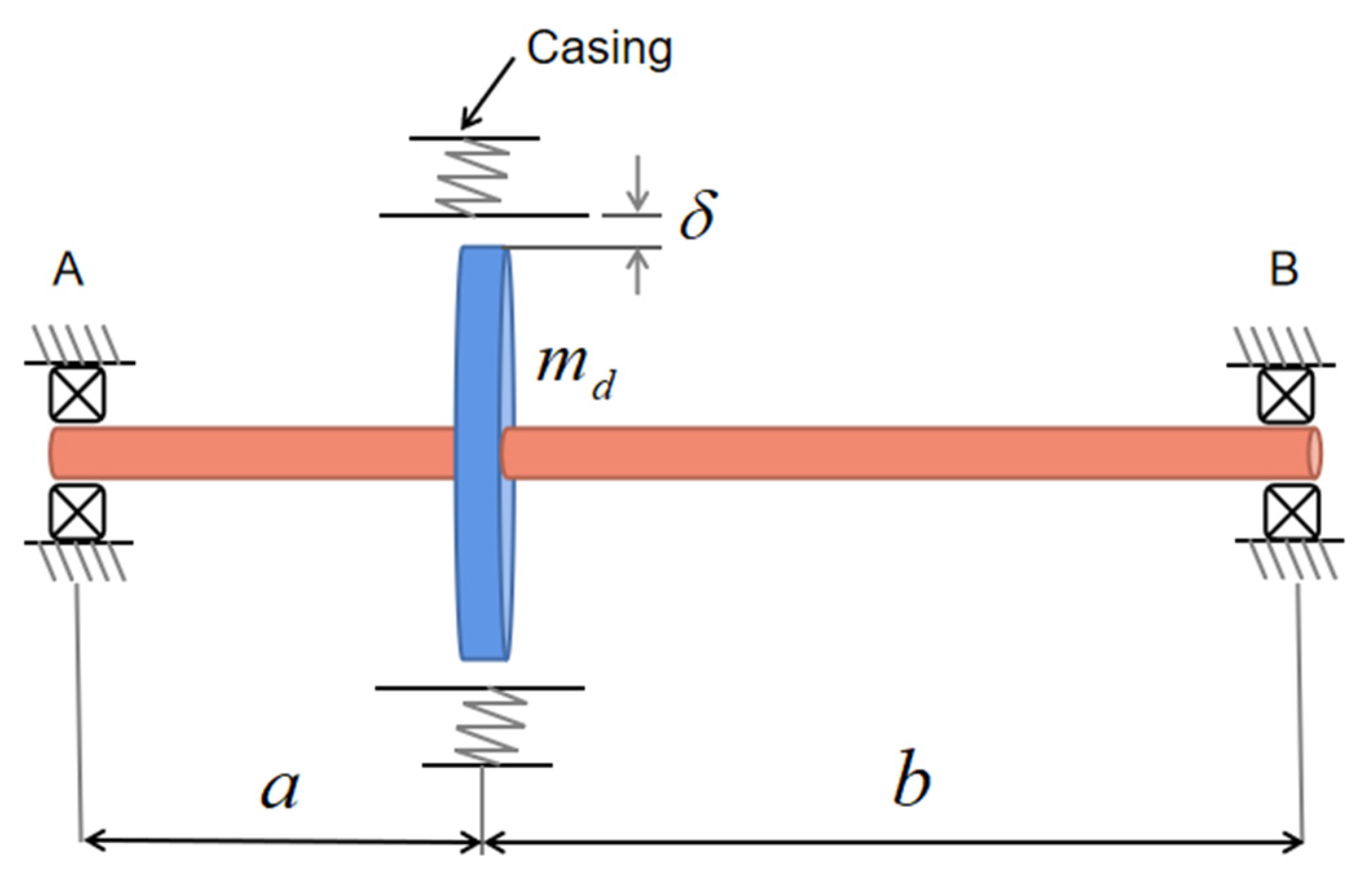
2.1. Misalignment Model
The misalignment of the two ends of the rotor supports leads to an angle between the driving torque and the shaft, which brings an additional bending moment to the rotor system. The schematic diagram of the misalignment model is shown in Figure 1. The airflow excitation force moment T is horizontally left, the misalignment angle is α; and the angle between the Ts moment and the y axis is β. T can be decomposed into Ta that coincides with the shaft and Ts that is perpendicular to the shaft, and Ts can be decomposed into Tx and Ty. According to the geometric relationship,
Figure 1.
Schematic diagram of the misalignment model.
Supposing that the displacement difference of the bearing misalignment at both ends of the rotor is Δx and Δy, respectively, then α and β are
Since the radial displacement of the rotor at the bearing is much smaller than the shaft length, α and β can be regarded as fixed values. According to Euler’s Equation for the rotation around a fixed point, Tx, Ty, Tz are expressed as
where ωi is the angular velocity of the rotor; Ii is the principal moments of the inertia of the rotor shaft, i = x, y, z; due to the rotation of the rotor around the z axis, ωx, ωy, , are all zero. Therefore, Euler’s Equation of rotating around a fixed point can be simplified as
where εz is the rotor angular acceleration. After deriving, the angular velocity and the misalignment angle satisfy the following relationship
where ω is the rotational angular velocity of the rotor; ωd is the angular velocity of the air-excited turbine disk; and θd is the angular displacement of the turbine disk. Under the small angle misalignment, the turbine disk and the rotor speed are equal, i.e., ωd ≈ ω. M and N are the coefficients related to the misalignment angle. M = 4cosα/(3 + cos2α), N = (1 − cos2α)/(3 + cos2α). After differentiating Equation (9), one can get
Substituting Equation (10) into Euler’s Equation, one can get
By decomposing the misalignment torque, it can be obtained
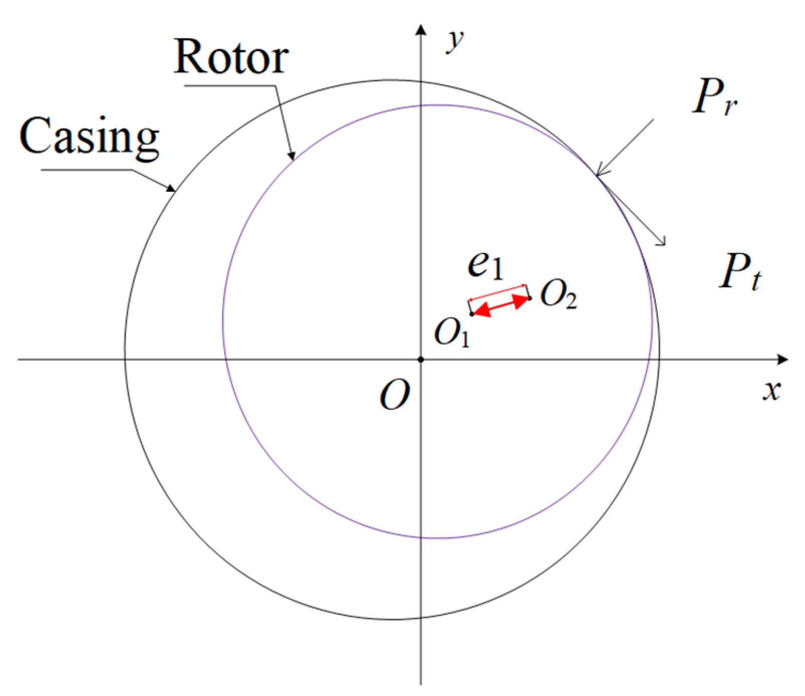
2.2. Rub-Impact Model
The rub-impact model is shown in Figure 2, where point O, O1 and O2 are the geometric center of the casing, the geometric center of the rotor and the mass center of the rotor (material defect and manufacturing tolerances are essentially reflected in the position of the mass center), respectively. The rub-impact force includes the radial collision force Pr and the tangential friction force Pt. The rubbing force conforms to the Coulomb Friction Law, and the rub-impact force can be expressed as []
Figure 2.
Rub-impact model between the rotor and casing.
By decomposing Pr and Pt into x-axis and y-axis, one can get:
where μ is the friction coefficient; k is the stiffness of the rub-impact, δ is the rub-impact clearance, x and y are the displacements in the x direction and y direction, respectively; and r is the radial displacement of the rotor disk center, .
2.3. Dynamic Model of the Rotor System
The dynamic model of the rotor system is developed based on the following assumption: torsional and axial displacement are ignored and the transverse bending vibration of the rotor system is considered; since the operating temperature of the rotor system is not high enough, the influences of temperature on material properties and system behaviors are small and can be ignored; after estimation, it is found that the gyro effect has a weak influence on the vibration of the rotor. Accordingly, the gyro effect is not considered in this work; the power turbine rotor is the whole forging rotor, the impeller and the shaft are integral, and there is no interaction between the components in the rotor system; the hub and blade are simplified as a rigid disk considering the rotation effect; and the shaft is simplified as a massless elastic shaft. A schematic diagram of the offset rotor system is shown in Figure 3. The mass of the disk is md, the eccentricity of the imbalanced disk is e, and the viscous damping of the disk in all directions is c; the clearance between the rotor and the casing is δ; the distance between the left support and the disk is a, the distance between the right support and disk is b, and the length of the shaft is l. These offset parameters have an influence on the vibration characteristics of the system. The dynamic characteristics under the determination offset will be studied in this work; the supporting mass at the left and right ends is ma and mb, the supporting stiffness is ka and kb, and the supporting viscous damping is ca and cb, respectively. In addition, the elastic modulus of the rotating shaft is E, and the moment of inertia of the cross section of the rotating shaft is I; the polar moment of inertia of the disk is Jp, and the moment of inertia of the disk diameter is Jd. The parameter values of the rotor system studied in this work are from a real rotor, as shown in Table 1.
Figure 3.
Schematic diagram of the offset rotor system.
Table 1.
The related parameters of the rotor system.
The equation of motion for the rotor system is established by using the Lumped Mass Method and the Lagrange Energy Equation. Lagrange equation is
where L = T − U; q represents the displacement of each degree of freedom; and F(t) is the external load of the system, the unbalanced force is considered in this study; compared with the unbalanced force, the influence of the aerodynamic force is negligible. The yaw angles of the wheel around the x axis and the y axis are θx and θy, respectively; the displacements of the bearing at the left and right ends in the x and y directions are xa, ya and xb, yb, respectively; the kinetic energy of the rotor system is
The generalized coordinates are
Potential energy of the rotor system
where Kx and Ky are the stiffness matrices of the o’xz plane and the o’yz plane of the rotor system, respectively.
where Kc is the stiffness matrix considering the axial bending deformation without elastic support, which can be obtained by the Stiffness Influence Coefficient Method and the Flexibility Influence Coefficient Method, and Φ1 is the biased matrix.
The dissipation energy of the disk is
The dissipative function supported at both ends is
The dissipative energy of the rotor system
The kinetic energy, the potential energy and the dissipation energy of the above rotor system are brought into the Lagrange Equation to obtain the dynamic equation of the coupled rotor system.
3. Results and Analyses
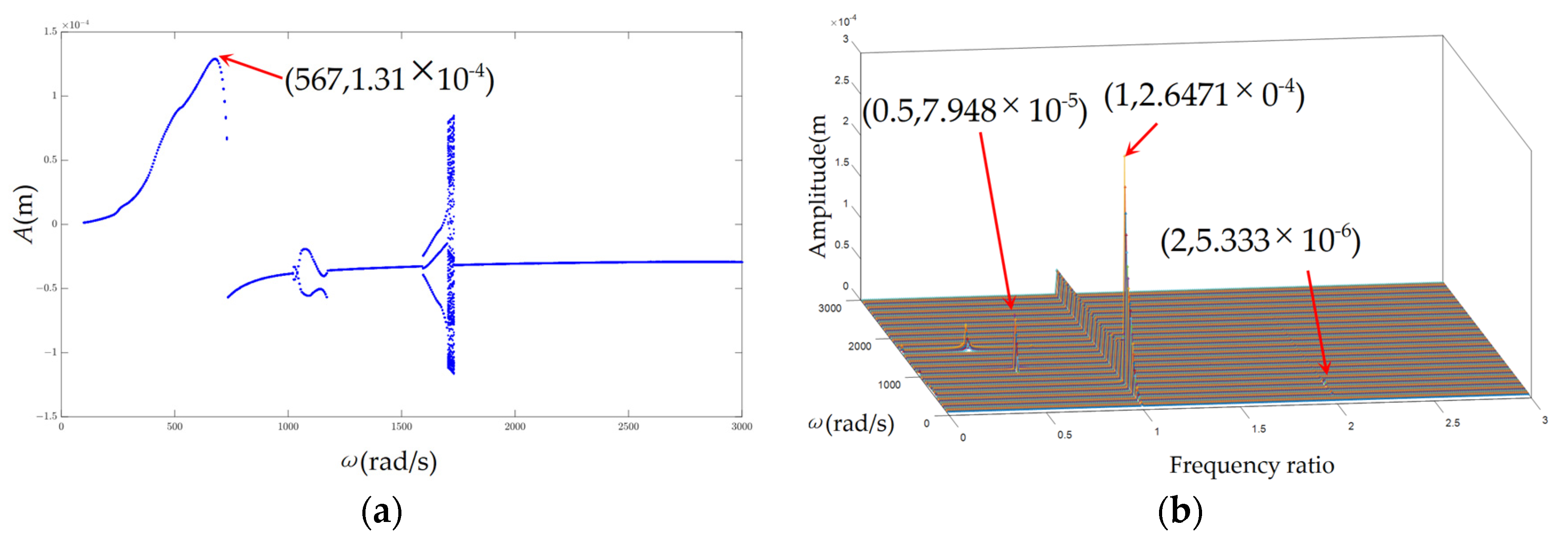
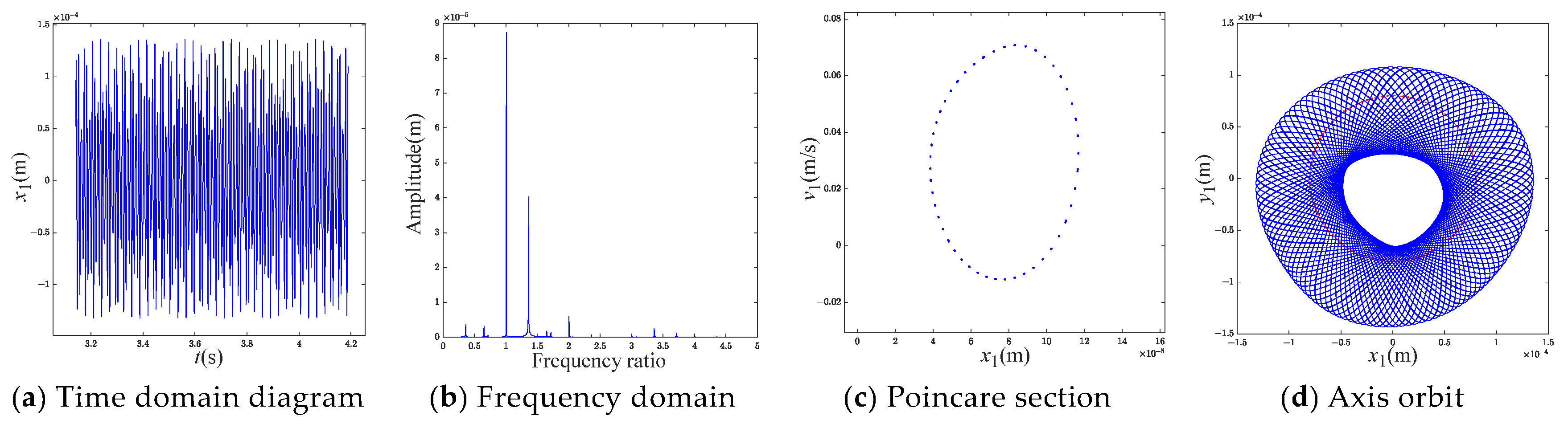
3.1. Rotating Speed
The rotating speed will change when the rotor system changes the operation mode and conditions or starts and stops. As an important parameter of rotating machinery, rotational speed has a significant impact on the dynamic characteristics of the system. When the rubbing clearance δ = 8 10−5 m, the rub-impact stiffness K = 2 107 N/m, the friction coefficient μ = 0.1, and the misalignment angle α = 3°, the bifurcation diagram of the vibration amplitude for the rotor with the change of the rotating speed under the misalignment fault is shown in Figure 4. It can be seen from Figure 4 that the vibration of the first-order critical speed occurs in the system, and the critical speed is 499 rad/s. After the speed increases to the critical speed, the amplitude of the vibration jumps from the positive to the negative direction. In addition, due to the small misalignment angle, the vibration at half the critical speed is not excited. The bifurcation diagram under the misalignment-rubbing coupling fault is shown in Figure 5, and the motions of the different speed intervals are shown in Table 2. It can be seen from Figure 5 that the system undergoes the period-1 motion, the quasi-period motion, the period-1 motion, the period-2 motion, the period-3 motion, the quasi-periodic motion and the period-1 motion in turn under the coupling fault. By comparing Figure 4 and Figure 5, it can be found that when the misalignment and rubbing faults exist at the same time, the critical speed of the system increases by 54% from 499 rad/s to 770 rad/s, and the Hopf bifurcation occurs; comparing the misalignment fault system, a new quasi-periodic motion of the coupling fault system appears in the range of 1726 rad/s~1832 rad/s.
Figure 4.
Bifurcation diagram of vibration amplitude with the change in rotating speed under the misalignment fault.
Figure 5.
Bifurcation diagram of vibration amplitude with the change in rotating speed under misalignment and rubbing faults.
Table 2.
The motion types for the different speed ranges.
When the rotating speed of the coupled fault system ω is 400 rad/s, 640 rad/s, 1100 rad/s, 1650 rad/s and 1780 rad/s respectively, the time domain, the spectrum, Poincare section and the axis trajectory diagrams are shown in Figure 6, Figure 7, Figure 8, Figure 9 and Figure 10. It can be seen from Figure 6d that the system has a rub-impact at this rotating speed. Due to the weak rub-impact, there are no other frequency components except the rotational frequency, as shown in Figure 6b. The system is in period-1, which is consistent with Figure 6a,c. The frequency components of 0.25X, 0.5X, 0.75X, 1.5X, 2X and 1.27X in Figure 7b are not conventions. The beat vibration is obvious in Figure 7a,c presents a similar circular curve; the corresponding axis orbit is shown in Figure 7d. It can be seen from Figure 8b that there are two dominant frequency components, 0.5X and 1X, which are in accord with Figure 8c; the amplitude of 0.5X is larger than that of 1X. From Figure 8d, the axis orbit is evolved from the 8-type trajectory; there are two peaks in Figure 8a, which correspond to the two closed circle-like curves in Figure 8d. There is a X/3 frequency division in Figure 9a; the Poincare section is divided into three independent scatter points, as seen in Figure 9c. However, when the rotating speed is 1785 rad/s, the system enters the quasi-periodic motion again. Figure 10c presents a curve like shamrock, and the axis trajectory is not disorderly, as shown in Figure 10d.
Figure 6.
(a) The time domain diagram; (b) the spectrum diagram; (c) Poincare section diagram; and (d) the axis trajectory diagram when ω = 400 rad/s.
Figure 7.
(a) The time domain diagram; (b) the spectrum diagram; (c) Poincare section diagram; and (d) the axis trajectory diagram when ω = 640 rad/s.
Figure 8.
(a) The time domain diagram; (b) the spectrum diagram; (c) Poincare section diagram; and (d) the axis trajectory diagram when ω = 1100 rad/s.
Figure 9.
(a) The time domain diagram; (b) the spectrum diagram; (c) Poincare section diagram; and (d) the axis trajectory diagram when ω = 1650 rad/s.
Figure 10.
(a) The time domain diagram; (b) the spectrum diagram; (c) Poincare section diagram; and (d) the axis trajectory diagram when ω = 1785 rad/s.
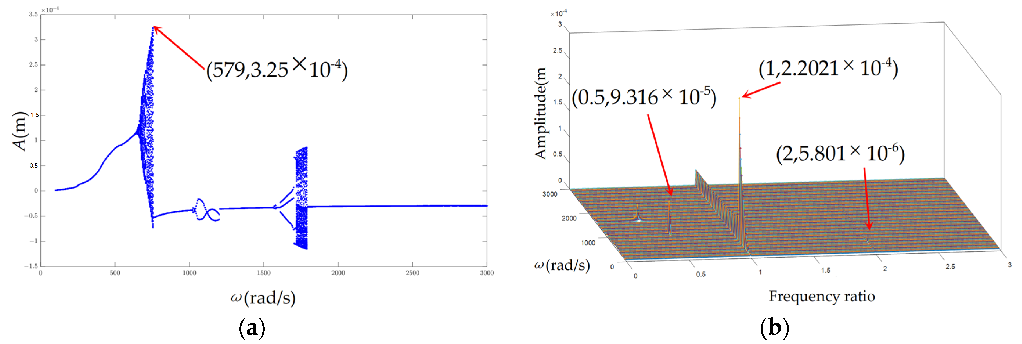
3.2. Misalignment Angle
The misalignment of the power turbine rotor system will also affect the vibration response. In order to study the influence of the misalignment of the rotor on the vibration, the misalignment angle α = 5°, 8° and 10° are selected as the control parameter, and the bifurcation and frequency waterfall diagrams are shown in Figure 11, Figure 12 and Figure 13. In Figure 11a, when the rotating speed is 586 rad/s, the system enters the quasi-periodic motion from the period-1 motion, i.e., the state of motion changes, the speed is accordingly called the switching speed, and the switching speeds for α = 8° and 10° are similarly 588 rad/s and 593 rad/s respectively, as shown in Figure 12a and Figure 13a. It can be seen from Figure 11a, Figure 12a and Figure 13a that when the misalignment angle increases, the vibration stability near half of the switching speed slumps, the maximum amplitude of the vibration response decreases, and the range of the quasi-periodic motion widens. Figure 11b, Figure 12b and Figure 13b show that with the increase of the misalignment angle, the maximum amplitude of the resonance decreases slightly.
Figure 11.
Bifurcation diagram and frequency waterfall diagram of vibration response when α = 5°. (a) Bifurcation diagram with the change in rotating speed. (b) Frequency waterfall diagram.
Figure 12.
Bifurcation diagram and frequency waterfall diagram of vibration response when α = 8°. (a) Bifurcation diagram with the change in rotating speed. (b) Frequency waterfall diagram.
Figure 13.
Bifurcation diagram and frequency waterfall diagram of vibration response when α = 10°. (a) Bifurcation diagram with the change of rotating speed. (b) Frequency waterfall diagram.
Chaos has intrinsic randomness, initial value sensitivity, and the characteristics of irregular order; therefore, a variety of tools is applied to judge chaos. Under the misalignment and rub-impact fault, when the speed ω is 600 rad/s, the bifurcation diagram of the amplitude with the misalignment angle is shown in Figure 14, which shows that the rotor system has experienced the quasi-periodic, the period-3, the period-6, the period-12, the period-4 and the chaotic motions. The time domain, the spectrum, Poincare and the axis orbit diagrams under the misalignment angles α = 7°, 9°, 11°, 14° and 16° respectively are shown in Figure 15, Figure 16, Figure 17, Figure 18 and Figure 19. It can be shown from Figure 15, Figure 16, Figure 17, Figure 18 and Figure 19 that with the increase of the misalignment angle, the amplitude of the 2X frequency gradually magnifies up to the first largest peak from the third largest peak in the spectrum diagrams. The other diagrams, such as the time domain, Poincare and the axis orbit, verify this point. The results show that the frequency of 2X is the characteristic frequency of the misalignment fault. When α = 11°, Figure 17c,d shows the system is in chaos, which is so unpredictable that this misalignment angle should be avoided in design.
Figure 14.
Bifurcation diagram with the change in misalignment angle.
Figure 15.
(a) The time domain diagram; (b) the spectrum diagram; (c) Poincare section diagram; and (d) the axis trajectory diagram when α = 7°.
Figure 16.
(a) The time domain diagram; (b) the spectrum diagram; (c) Poincare section diagram; and (d) the axis trajectory diagram when α = 9°.
Figure 17.
(a) The time domain diagram; (b) the spectrum diagram; (c) Poincare section diagram; and (d) the axis trajectory diagram when α = 11°.
Figure 18.
(a) The time domain diagram; (b) the spectrum diagram; (c) Poincare section diagram; and (d) the axis trajectory diagram when α = 14°.
Figure 19.
(a) The time domain diagram; (b) the spectrum diagram; (c) Poincare section diagram; and (d) the axis trajectory diagram when α = 16°.
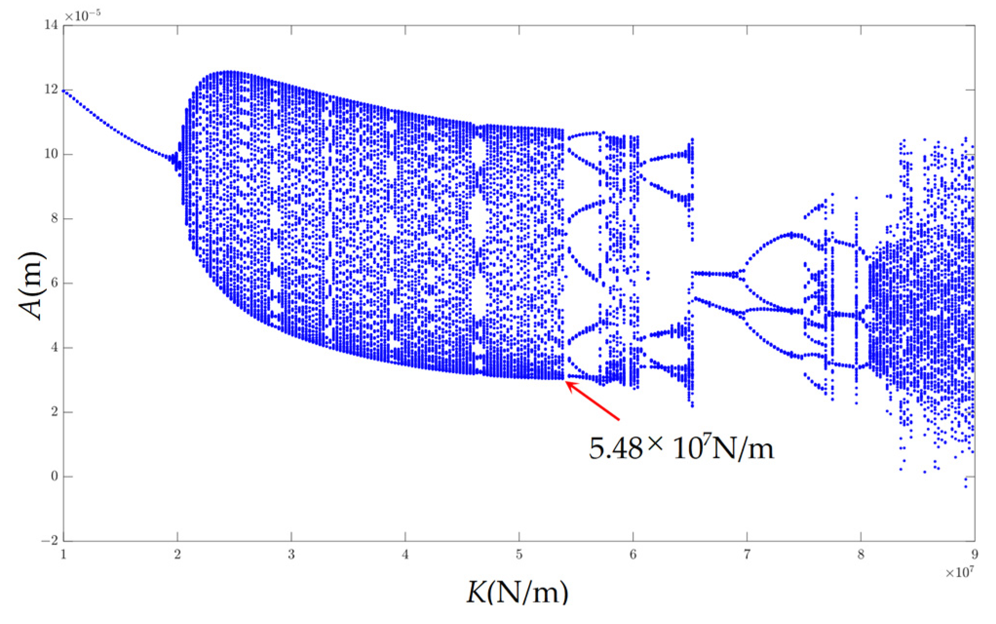
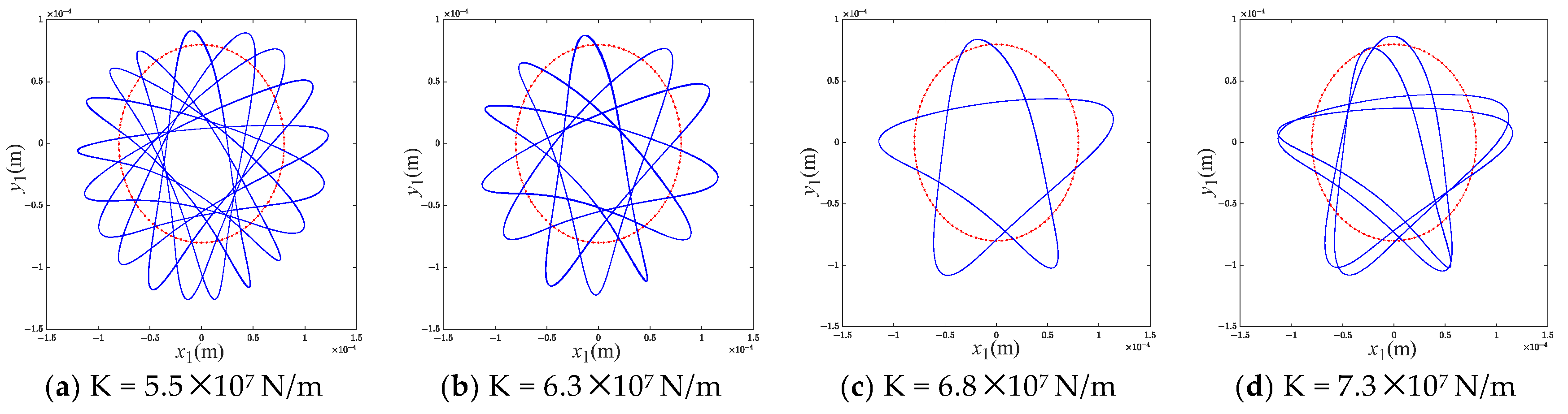
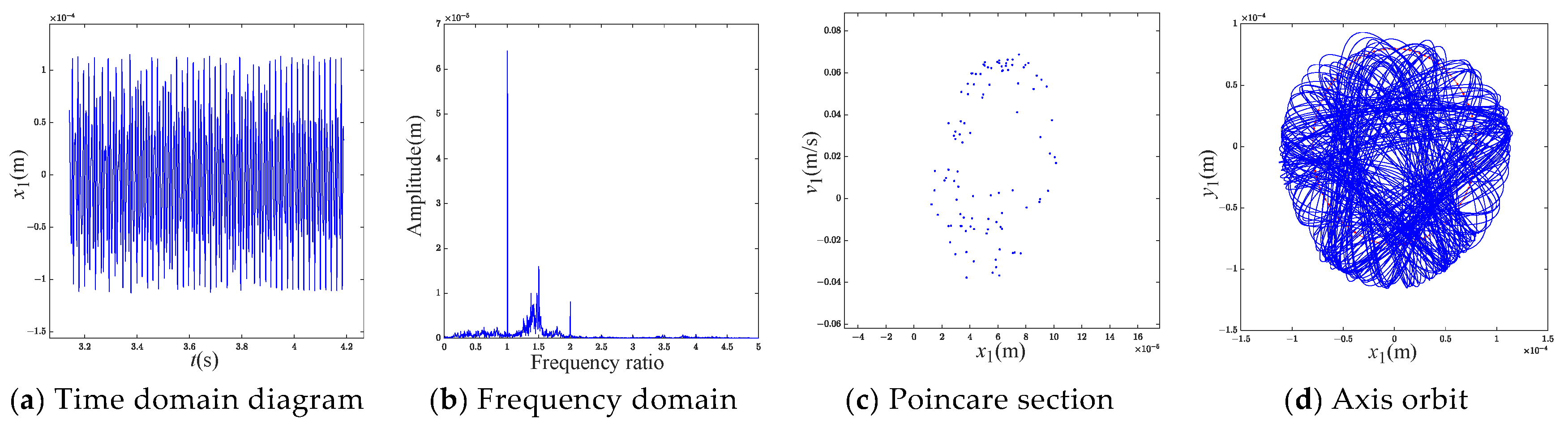
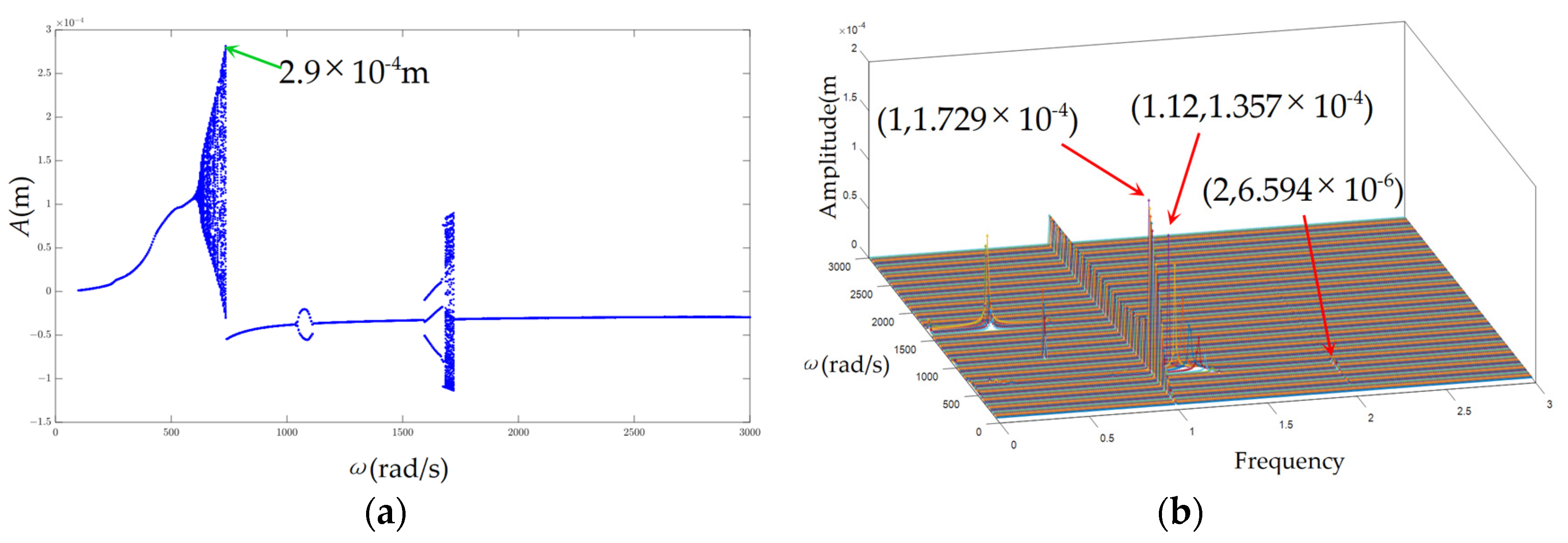
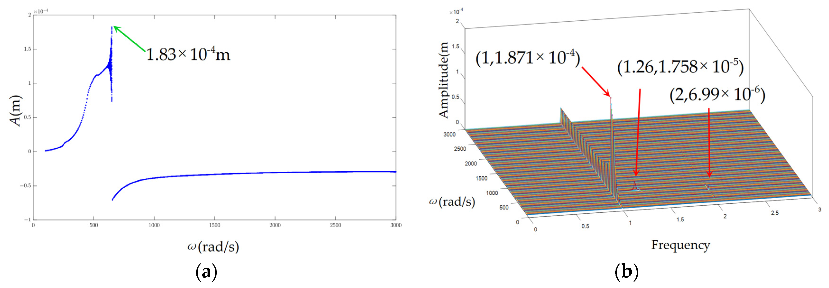
3.3. Stiffness of Rub-Impact
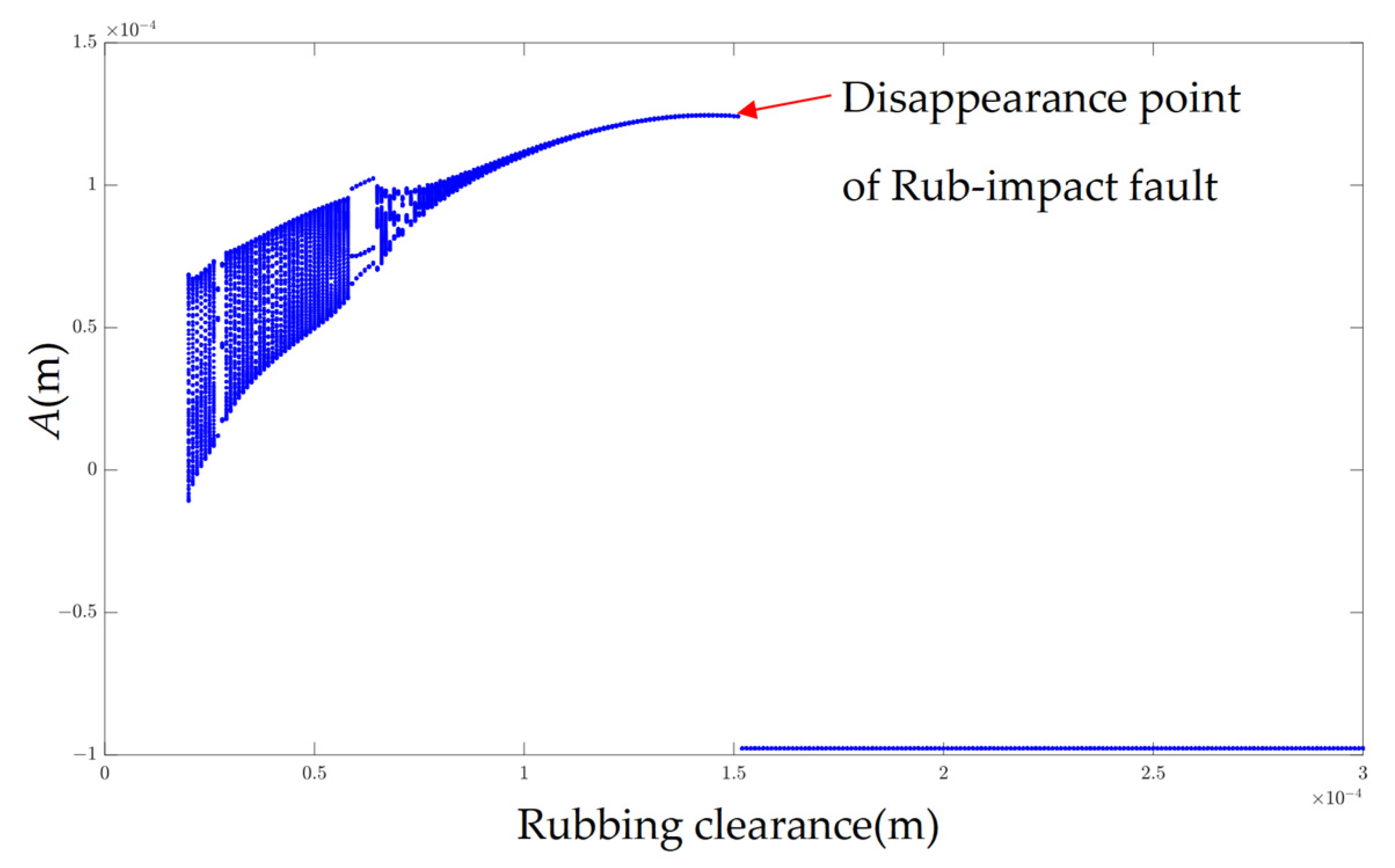
In the misalignment-rubbing coupling system, the rubbing force is one of the nonlinear sources of the rotor system. As a factor affecting the rubbing force, rubbing stiffness has an important influence on the vibration response. Keeping the rub-impact clearance unchanged, the misalignment angle is 3°, and the bifurcation diagrams and spectrum diagrams under stiffness K = 1.3 107 N/m, 1.5 107 N/m and 1.8 107 N/m are drawn, as shown in Figure 20, Figure 21 and Figure 22. It can be seen from Figure 20a, Figure 21a and Figure 22a that with the increase of the stiffness for the rub-impact, the number of the chaotic zone increases from zero to two; and the range of the chaos is widening, i.e., the larger the stiffness, the larger the unstable quasi-periodic motion interval. In addition, the corresponding critical rotational speeds are 561 rad/s, 567 rad/s and 579 rad/s respectively. This is because increasing the stiffness of the rub-impact will lead to an increase in the critical speed. It is found from Figure 20b, Figure 21b and Figure 22b that with the increase of the rub-impact stiffness, the maximum amplitude of the speed frequency decreases.
Figure 20.
Bifurcation diagram and frequency waterfall diagram of vibration response when K = 1.3 107 N/m. (a) Bifurcation diagram with the change in rotating speed. (b) Frequency waterfall diagram.
Figure 21.
Bifurcation diagram and frequency waterfall diagram of vibration response when K = 1.5 107 N/m. (a) Bifurcation diagram with the change of rotating speed. (b) Frequency waterfall diagram.
Figure 22.
Bifurcation diagram and frequency waterfall diagram of vibration response when K = 1.8 107 N/m. (a) Bifurcation diagram with the change in rotating speed. (b) Frequency waterfall diagram.
The bifurcation diagram of the rub-impact stiffness under the misalignment-rubbing coupling fault is drawn with the misalignment angle = 6°, as shown in Figure 23. It can be seen that with the increase of stiffness, the system goes through the period-1, the quasi-period, the period-8, the quasi-period, the period-5, the quasi-period, the period-2, the period-4, the multi-period, the period-3, the chaotic motions, intermittent inverted bifurcation, paroxysmal bifurcation, and so on.
Figure 23.
Bifurcation of rub-impact stiffness under misalignment-rubbing coupling fault.
When the stiffness is less than 2 × 10⁷ N/m, the system is in the period-1 motion because of the weak rub-impact characteristics under the small stiffness; the axis orbit is an ellipse, and there is a point in the Poincare section, as shown in Figure 24. With the increase of stiffness up to 3.5 107 N/m, the rub-impact characteristics are more and more obvious, and the vibration response is more and more complex. The system enters the quasi-periodic motion, and the beat vibration phenomenon is obvious, as shown in Figure 25; when the rubbing stiffness is 5.5 107 N/m, 6.3 107 N/m, 6.8 107 N/m and 7.3 107 N/m, the system is in the period-8, the period-5, the period-2 and the period-4 motion respectively, the axis trajectory is shown in Figure 26; when the rub-impact stiffness increases up to 8.8 107 N/m the system enters chaotic state whose characteristics are shown in Figure 27.
Figure 24.
(a) The time domain diagram; (b) the spectrum diagram; (c) Poincare section diagram; and (d) the axis trajectory diagram when K = 1.5 107 N/m.
Figure 25.
(a) The time domain diagram; (b) the spectrum diagram; (c) Poincare section diagram; and (d) the axis trajectory diagram when K = 3.5 107 N/m.
Figure 26.
Axial trajectory of periodic motion under different rubbing stiffness.
Figure 27.
(a) The time domain diagram; (b) the spectrum diagram; (c) Poincare section diagram; and (d) the axis trajectory diagram when K = 8.8 107 N/m.
3.4. Clearance
The clearance between the rotor and the stator is an important design parameter of the rotor system. Smaller cleara nce of the rub-impact is beneficial to improve mechanical efficiency, but it also brings the risk of the rub-impact fault. The clearance in the real world can be changed in some cases. To investigate the effect of the clearance on the dynamic characteristics, speed bifurcation and frequency waterfall diagrams under the different clearances are drawn, as shown in Figure 28, Figure 29 and Figure 30. By comparing Figure 28a, Figure 29a and Figure 30a, it can be seen that with the increase of clearance, the intervals of the quasi-periodic motion in the supercritical and critical speed regions decrease, and the maximum amplitude of the vibration decreases. Therefore, increasing the rubbing clearance is beneficial for enhancing the stability of the system. It can be seen from Figure 28b, Figure 29b and Figure 30b that the larger the clearance, the smaller the number of the rub-impact characteristic frequencies, and the weaker the degree of the rub-impact.
Figure 28.
Bifurcation diagram and frequency waterfall diagram of vibration response when δ = 9 10−5 m. (a) Bifurcation diagram with the change in rotating speed. (b) Frequency waterfall diagram.
Figure 29.
Bifurcation diagram and frequency waterfall diagram of vibration response when δ = 10 10−5 m. (a) Bifurcation diagram with the change in rotating speed. (b) Frequency waterfall diagram.
Figure 30.
Bifurcation diagram and frequency waterfall diagram of vibration response when δ = 12 × 10−5 m. (a) Bifurcation diagram with the change in rotating speed. (b) Frequency waterfall diagram.
The bifurcation diagram with the change in the rub-impact clearance is shown in Figure 31. It can be seen from Figure 31 that with the increase of the rub-impact clearance, the fluctuation range of the amplitude gradually narrows. The research shows that the system undergoes the quasi-period, the period-3, the quasi-period and the period-1 motions in turn. With increasing of the clearance up to 0.15 mm, the rub-impact disappears and there is a jumping phenomenon in the bifurcation diagram from the positive amplitude to negative amplitude.
Figure 31.
Bifurcation diagram with the change in rub-impact clearance.
In order to study the specific nonlinear dynamic characteristics of the system, the rub-impact clearance 3 × 10⁻⁵ m, 6 10−5 m and 12 10−5 m are chosen to draw the corresponding time domain, the spectrum, Poincare section and the axis trajectory diagrams, as shown in Figure 32, Figure 33 and Figure 34. It can be seen from Figure 32 that when the rub-impact clearance is 3 10−5 m, there is an obvious beat vibration phenomenon in Figure 32a, which shows a circular closed curve, indicating that the system is in the quasi-periodic motion state. In Figure 32d, there are annular curves; the amplitude of the frequency 1.35X generated by the rub-impact is significantly higher than that of the frequency 2X generated by the misalignment, as seen in Figure 32b. As the clearance increases, the degree of rub-impact is reduced, as shown in Figure 33.
Figure 32.
(a) The time domain diagram; (b) the spectrum diagram; (c) Poincare section diagram and (d) the axis trajectory diagram when δ = 3 10−5 m.
Figure 33.
(a) The time domain diagram; (b) the spectrum diagram; (c) Poincare section diagram; and (d) the axis trajectory diagram when δ = 6 10−5 m.
Figure 34.
(a) The time domain diagram; (b) the spectrum diagram; (c) Poincare section diagram; and (d) the axis trajectory diagram when δ = 12 × 10−5 m.
When the rub-impact clearance is 12 10−5 m, the vibration response is shown in Figure 34. In Figure 34b, no other frequency components except for the rotating speed frequency and the 2X frequency, and the amplitude of the 2X frequency is far less than that of the rotating speed frequency, indicating that the system is approximatively in period-1, Figure 34c,d verify this point.
4. Verification of the Theoretical Modeling Method
In order to verify the correctness of the modeling approach developed in this paper, the finite element model of the rotor system was established according to the same parameters and constraints as the theoretical modeling based on the Ansys Workbench platform, as shown in Figure 35.
Figure 35.
Finite element model and constraints of the rotor system.
The specific steps of the finite element analysis process are as follows: establishing the geometric model of the rotor system in Creo; importing the model into Ansys Workbench for finite element analysis; defining material property to keep it consistent with the data used in the theoretical calculation; meshing the model of the rotor system. The number of elements is 15,070, the number of nodes is 27,179, the type of the element is tet10, the mean jacobian ratio is 1.039, the mean element quality is 0.729, the mean aspect ratio is 2.27, the mean skewness is 0.407, the mean maximum turning angle is 1.815, these parameters are chosen as the quality check standards; imposing the constraints. The rotor is limited at the two ends by bearings; the bearings are equivalent to springs; the spring stiffness is 1.0 107 N/m which is consistent with the stiffness of theoretical calculation; the axial translation degrees of free (z direction) are limited; the vibrations of x direction and y direction are focused on; applying loads. The displacement response of the rotor vibration is calculated after applying the unbalanced load to the rotor.
After calculating, the time history curve and frequency domain diagram of the vibrational displacement at the center of mass for the disk under unbalanced load are drawn, and a comparison of the Finite Element Method (FEM) result and the Theoretical Modeling Method (TMM) result is carried out, as shown in Figure 36a,b. Because all the model parameters and boundary conditions are consistent with the theoretical calculation, the results of the finite element calculation and the theoretical calculation results are comparable. It can be shown from the figures that the theoretical and finite element calculations agree well, which validates the correctness of the theoretical modeling method.
Figure 36.
Comparison between FEM result and TMM result.
5. Conclusions
The power turbine rotor from the dual rotor system of the aircraft engine is taken as the research object. Considering the misalignment, the rub-impact, the imbalance and the disk offset of rotor, the equation of motion is established to study the influence of the rotating speed, the misalignment angles and the rub-impact clearance on the dynamic characteristics of the system; the finite element analysis was carried out to validate the correctness of the theoretical modeling method. The main conclusions are as follows:
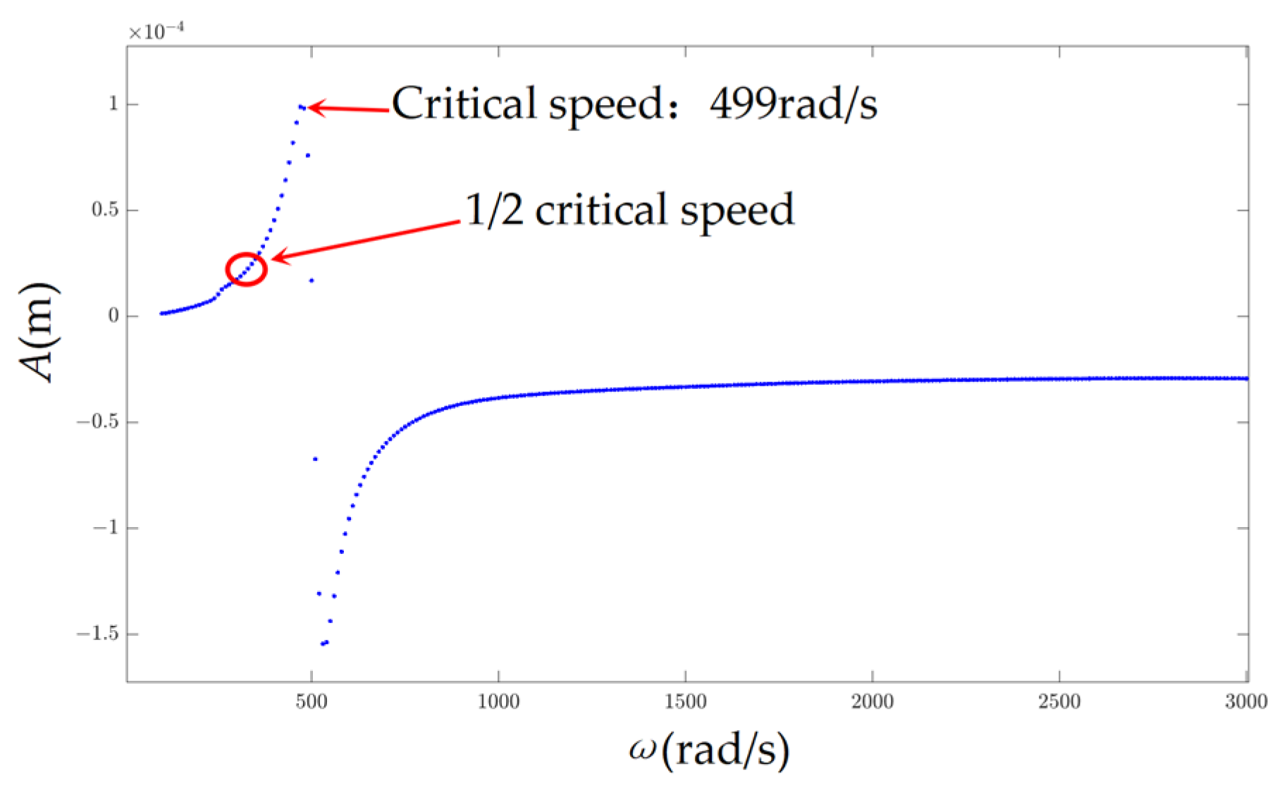
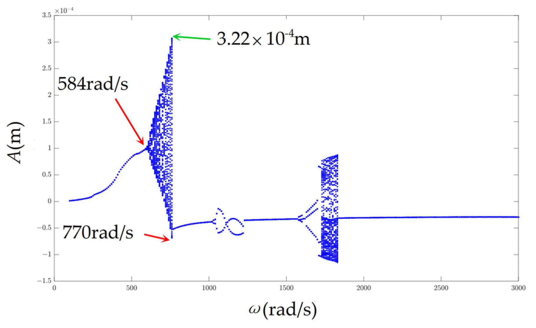
- The existence of the rub-impact increases the stiffness of the system, thereby increasing the critical speed. Compared with the system of the misalignment fault, the critical speed of the coupling fault system increases by 54%, and Hopf bifurcation occurs in the system.
- The vibration stability near half of the switching speed slumps with the increase of the misalignment angle, the maximum amplitude of the vibration response decreases, the range of the quasi-periodic motion is widening; the frequency 2X is the characteristic frequency of the misalignment. Besides, when α = 11°, the system is in the chaotic state, which is so unpredictable that this misalignment angle should be avoided in design.
- Increasing the rub-impact stiffness reduces the stability of the system. The rotor system with rub-impact is actually a nonlinear system with a non-smooth clearance. Rub-impact stiffness has important effects on the nonlinear characteristics of the system. With the increase of stiffness, the number of the chaotic zone increases; and the range of the chaos is widening; the maximum amplitude of the frequency at the critical speed decreases.
- Increasing the rubbing clearance is beneficial to reduce the degree of the rub-impact and enhance the stability of the system. With an increase in clearance, the interval of the quasi-periodic motion decreases, the maximum amplitude of the vibration decreases; the fluctuation range of the vibration gradually narrows. With an increase in clearance up to 0.15 mm, the rub-impact disappears and there is a reverse jumping phenomenon.
Author Contributions
Software (MATLAB 2021b, ANSYS 2020R2, CREO 9.0), D.Y.; Validation, S.Y.; Writing—original draft, G.N.; Writing—review & editing, S.Y. All authors have read and agreed to the published version of the manuscript.
Funding
This project is supported by the National Natural Science Foundation of China (Grant No. 52275118).
Institutional Review Board Statement
Not applicable.
Informed Consent Statement
Not applicable.
Data Availability Statement
The data presented in this study are available on request from the corresponding author (privacy).
Conflicts of Interest
The authors declare that they have no known competing financial interests or personal relationships that could have appeared to influence the work reported in this paper.
Nomenclature
| Kij | Element of ith row, jth column of the stiffness matrix |
| x, y | Displacement of the wheel in the x and y directions |
| xa, ya | Displacement of the bearing at the left end in the x and y directions |
| xb, yb | Displacement of the bearing at the right end in the x and y directions |
| Kx, Ky | Stiffness matrix of the o’xz plane and o’yz plane of the rotor system |
| Kc | Stiffness matrix considering the axial bending deformation without elastic support |
| θx, θy | Yaw angle of the wheel around the x axis and the y axis |
| Tx, Ty | Torsional moment in the x and y directions |
| ω | Rotational angular velocity of the rotor |
| ωd | Angular velocity of the air-excited turbine disk |
| px, py | Rub-impact force in the x and y directions |
| md, ma, mb | Mass of disk, left and right support |
| c, ca, cb | Damping of disk, left and right support |
| ka, kb | Support stiffness at left and right end |
| l, a, b | Shaft length and length between left, right ends and wheel |
| Acceleration of the wheel in the x and y directions | |
| Velocity of the wheel in the x and y directions | |
| Acceleration of the bearing at the left end in the x and y directions | |
| Velocity of the bearing at the right end in the x and y directions | |
| Acceleration of the bearing at the left end in the x and y directions | |
| Velocity of the bearing at the right end in the x and y directions | |
| Yaw angles acceleration of the wheel around the x axis and the y axis | |
| Yaw angles velocity of the wheel around the x axis and the y axis |
References
- Wang, P.; Xu, H.; Yang, Y.; Ma, H.; He, D.; Zhao, X. Dynamic characteristics of ball bearing-coupling-rotor system with angular misalignment fault. Nonlinear Dyn. 2022, 108, 3391–3415. [Google Scholar] [CrossRef]
- Zhang, H.; Huang, L.; Li, X.; Jiang, L.; Yang, D.; Zhang, F.; Miao, J. Spectrum Analysis of a Coaxial Dual-Rotor System with Coupling Misalignment. Shock. Vib. 2020, 2020, 5856341. [Google Scholar] [CrossRef]
- Lu, X.; Zhang, J.; Ma, L.; Lin, J.; Wang, J.; Wang, J.; Dai, H. Effects of misalignment on the nonlinear dynamics of a two-shaft rotor-bearing-gear coupling system with rub-impact fault. J. Vibroeng. 2017, 19, 5960–5977. [Google Scholar] [CrossRef]
- Fu, C.; Lu, K.; Yang, Y.; Xie, Z.; Ming, A. Nonlinear vibrations of an uncertain dual-rotor rolling bearings system with coupling misalignment. J. Nonlinear Math. Phys. 2022, 29, 388–402. [Google Scholar] [CrossRef]
- Kuan, L.; Hui, C.; Wentao, Z.; Haopeng, Z.; Kaifu, Z.; Chao, F. Nonlinear dynamic behavior of a dual-rotor bearing system with coupling misalignment and rubbing faults. J. Meas. Sci. Technol. 2023, 34, 014005. [Google Scholar] [CrossRef]
- Yang, L.H.; He, K.T.; Guo, Y.L. Reliability analysis of a nonlinear rotor/stator contact system in the presence of aleatory and epistemic uncertainty. J. Mech. Sci. Technol. 2018, 32, 4089–4101. [Google Scholar] [CrossRef]
- Hou, L.; Chen, Y.; Fu, Y.; Li, Z. Nonlinear response and bifurcation analysis of a Duffing type rotor model under sine maneuver load. J. Nonliner Mech. 2016, 78, 133–141. [Google Scholar] [CrossRef]
- Ma, H.; Tai, X.; Han, Q.; Wu, Z.; Wang, D.; Wen, B. A revised model for rubbing between rotating blade and elastic casing. J. Sound Vib. 2015, 337, 301–320. [Google Scholar] [CrossRef]
- Li, B.; Ma, H.; Zeng, J.; Guo, X.; Wen, B. Rotating blade-casing rubbing simulation considering casing flexibility. Int. J. Mech. Sci. 2018, 148, 118–134. [Google Scholar] [CrossRef]
- Zeng, J.; Ma, H.; Yu, K.; Guo, X.; Wen, B. Rubbing response comparisons between single blade and flexible ring using different rubbing force models. Int. J. Mech. Sci. 2019, 164, 105164. [Google Scholar] [CrossRef]
- Guo, X.; Zeng, J.; Ma, H.; Zhao, C.; Yu, X.; Wen, B. A dynamic model for simulating rubbing between blade and flexible casing. J. Sound Vib. 2019, 466, 115036. [Google Scholar] [CrossRef]
- Chen, G.; Li, X.Y. Study on imbalance-misalignment-rubbing coupling faults in aero-engine vibration. J. Aerosp. Power 2009, 24, 2277–2284. [Google Scholar]
- Chen, G. Simulation of casing vibration resulting from blade–casing rubbing and its verifications. J. Sound Vib. 2016, 361, 190–209. [Google Scholar] [CrossRef]
- Prabith, K.; Krishna, I.R.P. Response and stability analysis of a two-spool aero-engine rotor system undergoing multi-disk rub-impact. Int. J. Mech. Sci. 2022, 213, 106861. [Google Scholar] [CrossRef]
- Prabith, K. A dual-shaft aero-engine rotor system, performs the response and stability analysis of multi-disc friction impact. J. Mach. Sci. Sci. 2022, 213, 106861. [Google Scholar]
- Xie, W.; Liu, C.; Wang, N.; Jiang, D. Numerical and experimental analysis of rubbing–misalignment mixed fault in a dual-rotor system. Proc. Inst. Mech. Eng. Part C J. Mech. Eng. Sci. 2020, 235, 3179–3198. [Google Scholar] [CrossRef]
- Liu, Y.; Xin, X.; Zhao, Y.; Ming, S.; Ma, Y.; Han, J. Study on Coupling Fault Dynamics of Sliding Bearing-Rotor System. J. Comput. Nonlinear Dyn. 2019, 14, 041005. [Google Scholar] [CrossRef]
- Yu, J.J.; Goldman, P.; Bently, D.E.; Muzynska, A. Rotor/Seal Experimental and Analytical Study on Full Annular Rub. J. Eng. Gas Turbines Power 2002, 124, 340–350. [Google Scholar] [CrossRef]
- Zhang, Z.; Ma, X.; Hua, H.; Liang, X. Nonlinear stochastic dynamics of a rub-impact rotor system with probabilistic uncertainties. Nonlinear Dyn. 2020, 102, 2229–2246. [Google Scholar] [CrossRef]
- Sun, W.; Yan, Z.; Tan, T.; Zhao, D.; Luo, X. Nonlinear characterization of the rotor-bearing system with the oil-film and unbalance forces considering the effect of the oil-film temperature. Nonlinear Dyn. 2018, 92, 1119–1145. [Google Scholar] [CrossRef]
- Liu, Y.; Dou, J.X.; Wen, B.C. Identification technique of misalignment-rubbing coupling fault in dual-disk rotor system supported by rolling bearing. J. Vibroeng. 2015, 17, 287–299. [Google Scholar]
- Liu, Y.P.; Tai, X.Y. Dynamic characteristics of misalignment-rubbing coupling fault for rotor system. J. Dongb Daxue Xuebao/J. Northeastern Univ. 2013, 34, 564–568. [Google Scholar]
- Han, T.; Xie, W.Z.; Pei, Z.Y. Semi-supervised adversarial discriminative learning approach for intelligent fault diagnosis of wind turbine. J. Inf. Sci. 2023, 648, 119496. [Google Scholar] [CrossRef]
- Saeed, N.A.; Awrejcewicz, J.; Hafez, S.T.; Hou, L.; Aboudaif, M.K. Stability, bifurcation, and vibration control of a discontinuous nonlinear rotor model under rub-impact effect. Nonlinear Dyn. 2023, 111, 20661–20697. [Google Scholar] [CrossRef]
- Jin, M.; Wang, A.L.; Wang, Q.; Wang, L. Rub-impact dynamic analysis of the central tie rod rotor-blade-casing coupling system with the Hirth couplings connection. J. Vib. Eng. Technol. 2023, 1–25. [Google Scholar] [CrossRef]
- Abouelanouar, B.; Elkihel, A.; Gziri, H. Experimental study on energy consumption in rotating machinery caused by misalignment. J. SN Appl. Sci. 2020, 2, 1215. [Google Scholar] [CrossRef]
- Fu, C.; Zhu, W.; Zheng, Z.; Sun, C.; Yang, Y.; Lu, K. Nonlinear responses of a dual-rotor system with rub-impact fault subject to interval uncertain parameters. J. Mech Syst Signal Process. 2022, 170, 108827. [Google Scholar] [CrossRef]
Disclaimer/Publisher’s Note: The statements, opinions and data contained in all publications are solely those of the individual author(s) and contributor(s) and not of MDPI and/or the editor(s). MDPI and/or the editor(s) disclaim responsibility for any injury to people or property resulting from any ideas, methods, instructions or products referred to in the content. |
© 2024 by the authors. Licensee MDPI, Basel, Switzerland. This article is an open access article distributed under the terms and conditions of the Creative Commons Attribution (CC BY) license (https://creativecommons.org/licenses/by/4.0/).