You are currently viewing a new version of our website. To view the old version click .
Applied Sciences
  • Article
  • Open Access

11 December 2024

A Multi-Phase Brushless Direct Current Motor Design and Its Implementation in Medium-Altitude Long-Endurance Unmanned Aerial Vehicles

,
,
and
Department of Electrical Engineering, Yıldız Technical University, Istanbul 34220, Türkiye
*
Author to whom correspondence should be addressed.
This article belongs to the Section Aerospace Science and Engineering

Abstract

Nowadays, electric propulsion system implementation in vehicles is popular, and many studies and prototypes have been accomplished in this field. Aircraft are important members of the vehicle family, and Unmanned Aerial Vehicles (UAVs) are part of this family as well. Some UAVs still have conventional propulsion systems, which are less efficient and are harmful to the environment. In addition, conventional systems are vulnerable to faults in their propulsion system components. To overcome these problems, we designed a multi-phase Brushless Direct Current (BLDC) motor, to achieve fault-tolerant operation. Our designed BLDC motor was implemented in a UAV model that was created on MATLAB Simulink, based on a currently used UAV. Our design and performance analysis are shown for the BLDC motor, both standalone and as implemented in the created UAV model. The electric propulsion system performance is shown, according to the determined flight profile. We observed that the designed electric machine is capable of producing the required torque to create thrust for lifting the UAV. There are some advantages and disadvantages to using the designed electric machine in this class of UAV. This is shown in the related sections.

1. Introduction

Electrification of conventional powertrain systems in vehicles is a popular topic, because of concerns about global warming, remaining fossil fuel sources and efficiency [1,2,3]. Conventional systems are harmful to the environment, because they emit hazardous gases into the air. Also, they are less efficient compared to electric motors. The average efficiency of a conventional propulsion system that uses fossil fuels as a power source is about 40%, while electric motors have an efficiency of over 90% [4,5,6]. In addition, it is been known that fossil fuel sources are decreasing year by year and as a result of that alternative power sources are being searched for, to prevent any limitations or disruptions in vehicle operations caused by a limited supply of fossil fuels [7]. In this regard, electric motors are feasible to use instead of conventional ones. The More Electric Aircraft (MEA) and All Electric Aircraft (AEA) concepts were created to convert conventionally powered systems to electrically powered systems. These concepts also include powertrain systems, and this is an expanding area in which to work, for the reasons mentioned above. Unmanned Aerial Vehicles (UAVs) are also among the aircraft that are growing more popular day by day, because of their environmentally friendly, silent and efficient operations [8,9,10,11,12,13]. They are classified according to their weights, range and operating altitude. Some UAVs already have electrified propulsion systems. However, some of them use a conventional Internal Combustion Engine (ICE) as a propulsion system. One class is named the Medium-Altitude Long-Endurance (MALE) UAV [14,15,16]. Long range and endurance are significant characteristics of this type of UAV. For this reason, it is not easy to implement an electric propulsion system on this platform, because of current battery technology. The topology of an electric propulsion system is shown in Figure 1:
Figure 1. Schematic representation for electric-powered propulsion system.
It can be seen from Figure 1 that an electric motor is powered by a battery and that it is not feasible for long-endurance operation because of its limited power supply, due to current battery technology. Despite this disadvantage, it can still be used, depending on the mission type or duty requirement [17,18,19]. To create an electrically powered UAV, a Brushless DC (BLDC) motor was selected as the powertrain and designed anew for this study. It was selected because of BLDC motors’ easy and precise control of speed, and their reliability, low cost, easy maintenance, high torque–weight ratio, high efficiency, and low noise operation [20,21]. On the other hand, reliability is a crucial factor, especially in aviation, and the components used in aviation must be dependable. To provide reliable operation with our designed electric propulsion system, the BLDC motor was created as a five-phase motor. Our aim was an electric motor that could produce the required torque to fly an aircraft even in the failure state of the motor phases [22,23,24]. In this study, our multi-phase BLDC motor was designed and implemented in a UAV model, which was selected from currently used UAVs in the industry, with computer-aided programs. After the design and implementation processes, the performance of the designed electric propulsion system was observed with a system-level model of the designed motor. In the Section 2 below, our BLDC motor design, its parameters and the creation and implementation of the UAV model are explained. To run the simulations for a purpose, a flight profile was created, and the simulations were run according to this profile. In Section 3, we show the obtained outcomes of the simulations, with both graphical and tabulated data. Our displayed results are evaluated and criticized in the Section 4. To sum up and finalize our obtained results, we show our final assessments in Section 5.

2. Methodology

This section provides an overview of the methodology that was employed in this study, which encompassed the multi-phase BLDC motor, the UAV model creation and the determination of the flight profile. This explanation will be supplemented with equations, figures, and tables, to enhance clarity and understanding.

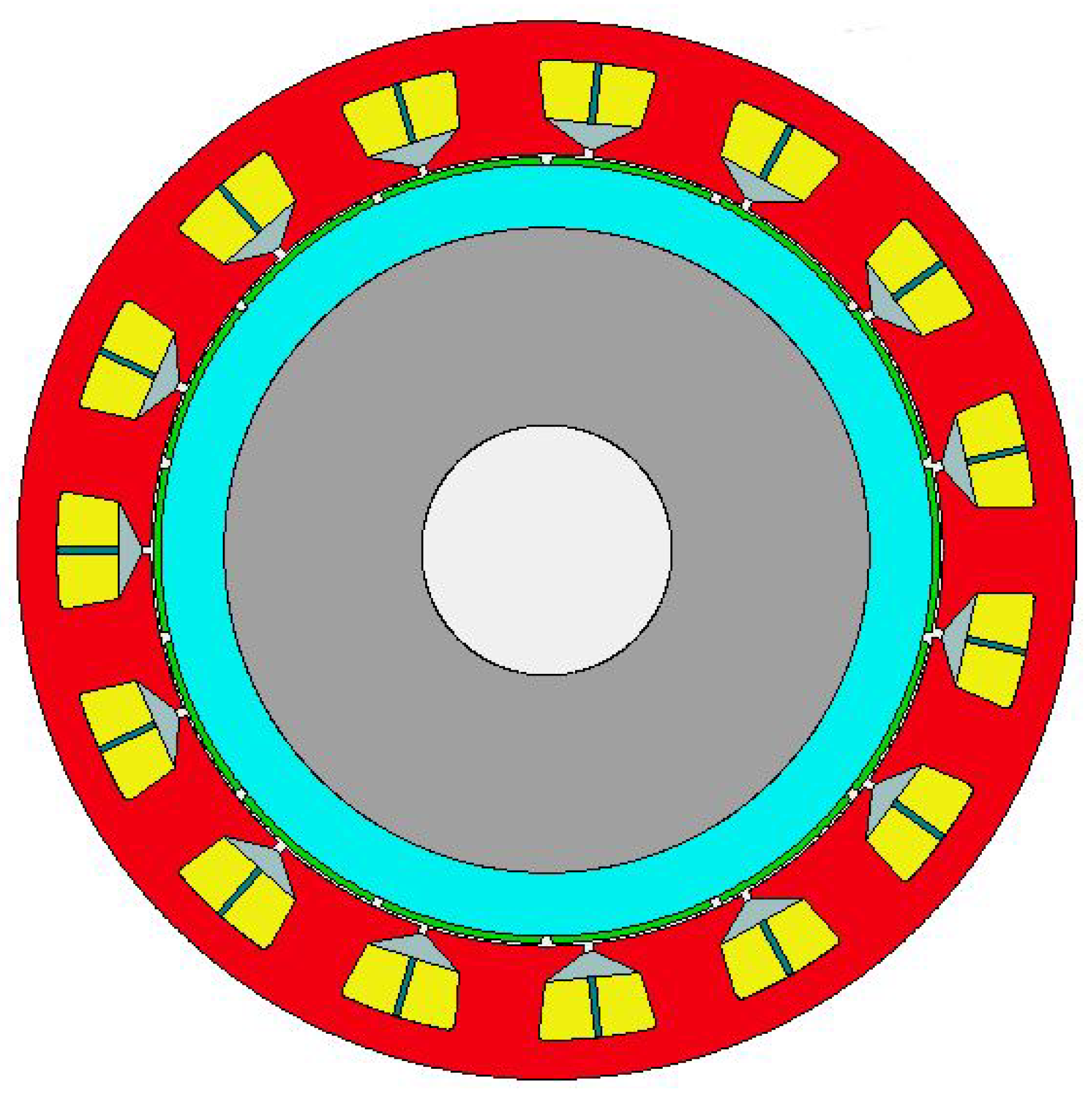
2.1. Multi-Phase BLDC Motor Design

The design process began with the determination of the initial parameters, which were rated power, speed, slot/pole combination, DC terminal voltage and number of phases. As mentioned in our Introduction, the machine’s number of phases selected was five, as a concept of multi-phase. In Table 1, we show our determined initial parameters:
Table 1. Initial parameters of designed multi-phase BLDC motor.
After determining the initial parameters, the machine’s main dimensions were calculated. This was affected by the flux densities of the components, the aspect ratio of the machine and the current density of the stator windings. The related Equations (1)–(3) are shown below. With these equations, the machine’s main dimensions, which were stator diameter and stack length, were ascertained [25,26].
D 2 l = P C ( n 60 )
X = p 3 π 2 p
C = π 2 k w A B 2
The number of turns was also calculated, following the determination of the main dimensions by Equations (4) and (5). According to the number of turns, the stator slot and tooth dimensions could be calculated. In this regard, the magnet dimension could also be calculated by Equation (6) [25]. The obtained results are shown in Table 2:
N = 2 E ω k w l τ p α B
E = 0.95 V d c
d m = B ( ( μ m ) / ( μ 0 ) ) g m K l K r g g m K l B r B
Table 2. Calculated parameters for the designed machine.
Our designed machine could be modeled with the calculated parameters, using a computer-aided program, which was ANSYS Motor-CAD Version 14.1.5.1. The modeled machine is shown in Figure 2. The materials of the stator and rotor back iron, magnets and phase windings are shown in Table 3. The physical modeling of the new designed machine was completed at this stage with the calculated parameters shown above.
Figure 2. Designed multi-phase BLDC motor general visualization.
Table 3. Materials of the designed machine.

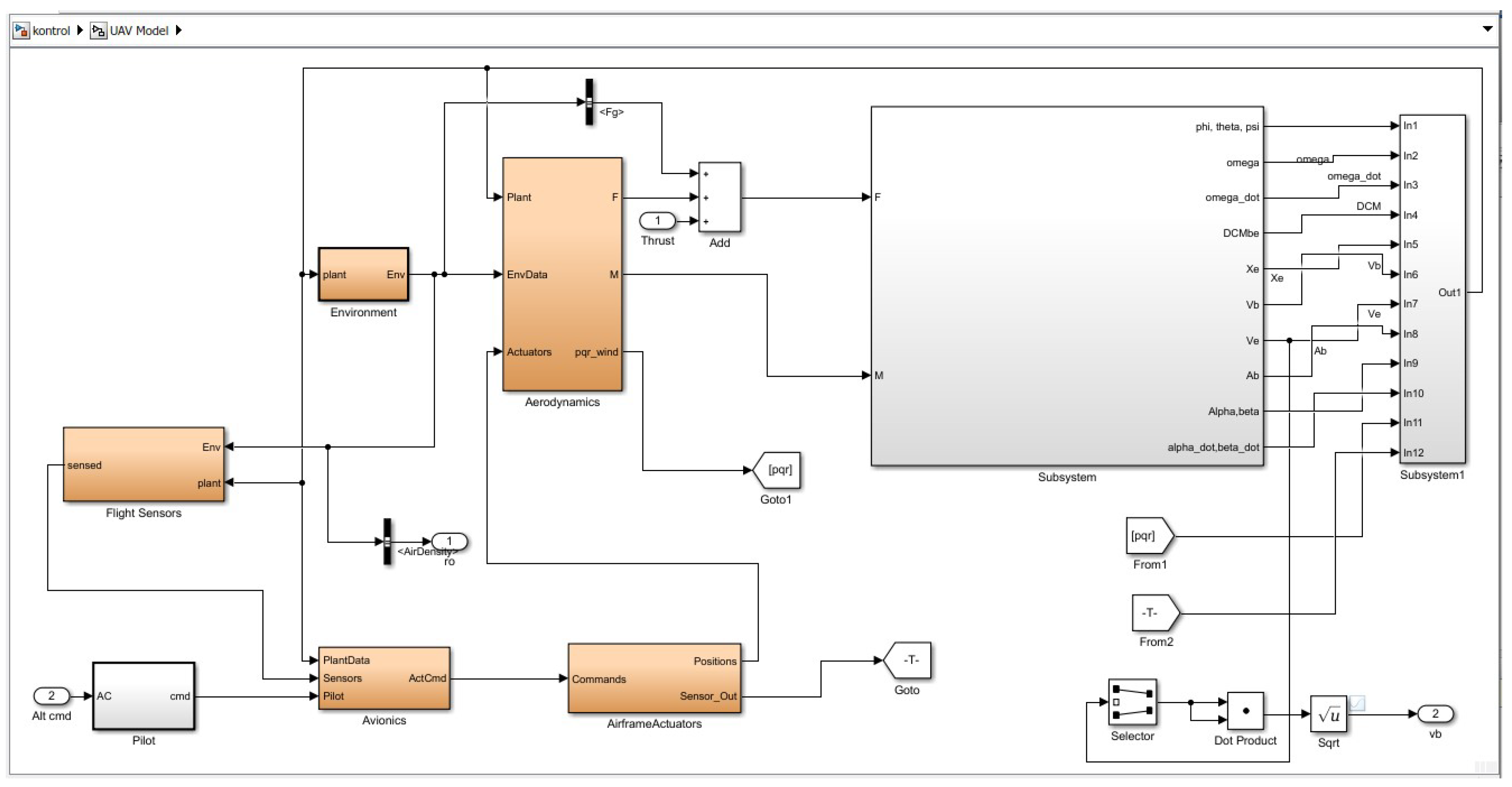
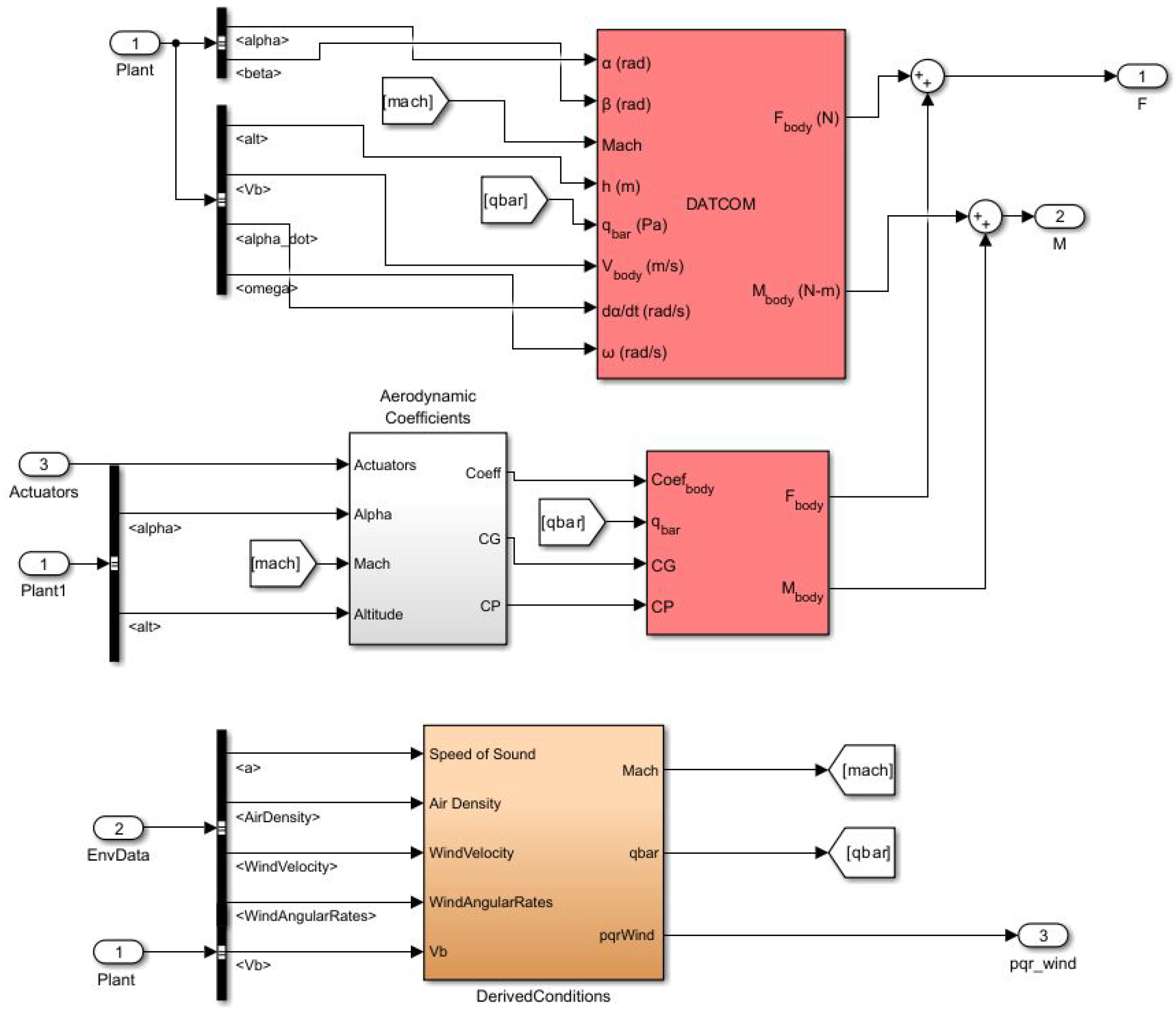
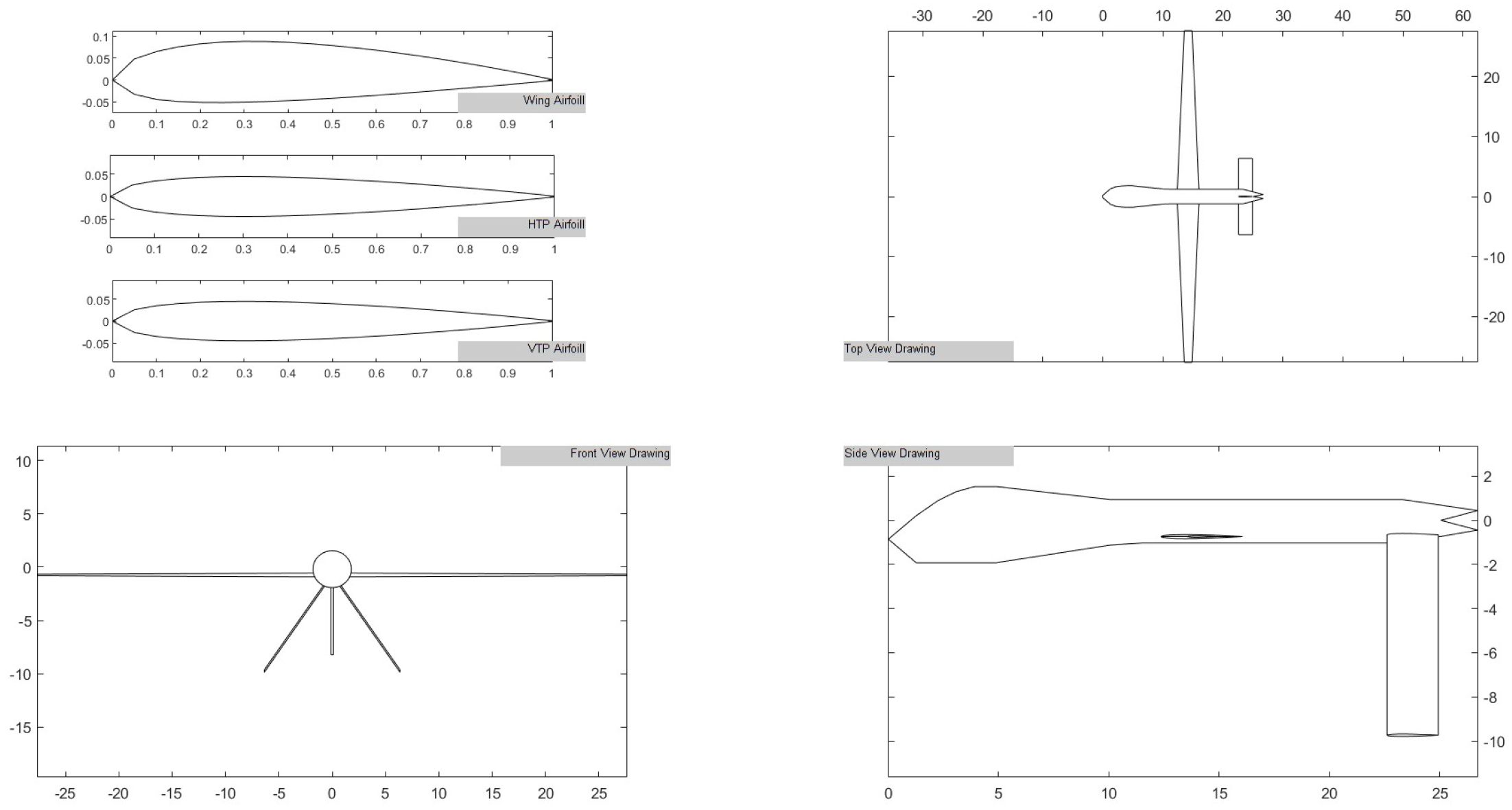
2.2. Development of UAV Model and Auxiliary Components

A reference UAV model was selected from among the currently used UAVs in the determined class. The selected UAV’s parameters are shown in Table 4 [27]. A computer-aided model of the UAV and the auxiliary components, such as environment, movement control, etc., was created in MATLAB R2023a Simulink. To import aerodynamic forces based on wing span, the airfoil type, weight, angle of attack, speed and altitude were calculated with USAF DATCOM software version date 1979 [28]. The calculated parameters were imported to MATLAB Simulink as data tables and a package.
Table 4. Main parameters of reference UAV.
The created UAV model with all sub-components is shown in Figure 3. Related modeling includes environmental models that contain wind and gravity, a control block which is for stabilizing the aircraft at the desired altitude and aerodynamic forces that were created by DATCOM softwareversion date 1979. The environmental model includes wind effects and gravitational forces, which were based on the aircraft’s altitude and the weight onboard. The pilot block commanded the desired aircraft altitude, according to the flight profile. The airframe actuators block commands to elevate surfaces to maintain the desired altitude according to the pilot’s command which is based on flight profile. Note that only the elevator command was considered and that the yaw and roll commands were not simulated in this study. There is also a subsystem, which contains a 3 DoF-to-6 DoF (Degrees of Freedom) conversion block. This block is obtaining applied forces and momentum data to the aircraft and convert it to 6 DoF parameters with using related calculation blocks. As a result of these calculations, the related parameters were sent adequate blocks as the feedback and flight simulation model was completed [29,30].
Figure 3. Components of the created UAV model on MATLAB-Simulink.
The aerodynamics blocks include aerodynamic parameters that was created and implemented by USAF DATCOM software version 1979. This related block is shown in Figure 4. The affected values of force and momentum which are occurred by the aircraft’s altitude, Mach, elevator position, angle of attack and pitch angle are created in this block. In addition, there were also additive forces and momentum that came from the elevator movement. According to the flight profile, the elevator movement was needed to reach the target altitude value. As a result of the elevator command, additional forces and momentum were applied to the aircraft. The sum of these forces and moments created total value that was applied to the aircraft. There was another block, which represented derivative conditions that calculated the mach and barometric pressure values based on feedback from the environment.
Figure 4. Representation of aerodynamic block in UAV model.
The modeled UAV, which was based on the imported parameters, is shown in Figure 5. The model is shown from different angles: top, bottom and rear. Also shown is the airfoil type of wing, which affected the aerodynamic parameter’s calculation.
Figure 5. Visualization of created UAV model.

2.3. Integration of Battery Model

The designed BLDC motor was required to connect to a battery model that would supply running power. The battery model was created on MATLAB Simulink. For this study, the currently certified battery that was used in the Pipistrel electric aircraft was selected. The parameters of the battery are shown in Table 5 [31]:
Table 5. Main parameters of the battery.

2.4. Flight Profile

A flight profile was created, to observe the performance of the designed BLDC motor in normal operation. For this purpose, the flight profile was created with the following parameters. Altitude is starting with 3000 m (9842 ft) and then changed to 3500 m (11,482 ft), and after that shifted to 1500 m (4921 ft). The altitude selection was triggered over time. Yaw and roll movements were not simulated, as mentioned above. Cruise speed was set to 50 m/s, based on the UAV specification. Both mission profiles ended when the State of Charge (SoC) value reached 20%. Note that only 1 battery was used to simulate the related mission profiles.

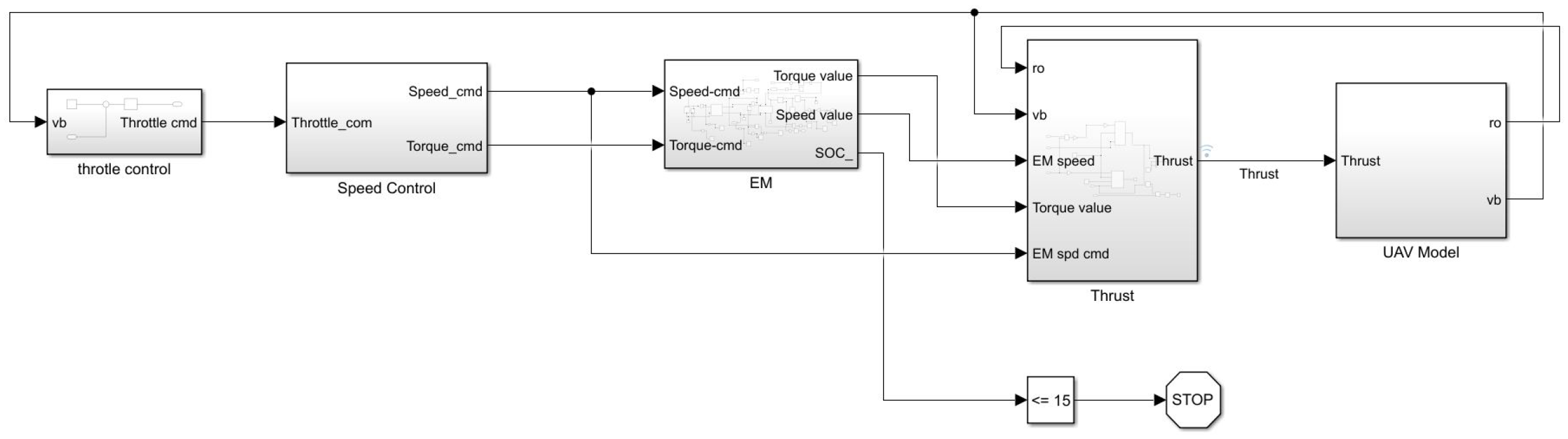
2.5. Combination of Separately Designed Blocks

In addition to the main blocks, which were the Electric Motor and the UAV model, there were also supportive blocks for controlling the flight phases and calculations. The throttle control, speed control and thrust blocks were responsible for calculation and avoiding violation of the design limitations of the UAV. The combined model, with all the related blocks, is shown in Figure 6. The throttle control block was responsible for applying adequate throttle command to the speed block, to maintain tbe aircraft’s desired speed. The speed control block provided the reference torque and speed value of the electric machine, based on the commands that came from the throttle block. The Electric Motor (EM) block had a system-level model of the designed machine and battery model. The outputs of this block were shaft torque and speed value, which were connected to the thrust calculation block. The thrust calculation block had propeller data and thrust value, which were calculated with the electric motor shaft speed and propeller parameters. The propeller’s specifications are shown in Table 6. The last block was the UAV model, which was explained in the previous sections, and the thrust value was connected to here, which was added to the other forces on the aircraft.
Figure 6. Combined model representation with all blocks.
Table 6. Specifications of propeller.

3. Results

In this section, the calculated and obtained values after simulation, which were mentioned in the Section 2 above, are shared, with graphical and tabulated materials. The displayed electrical motor parameters were selected based on their importance in the design process and their effects on the flight phases of the UAV, such as speed, torque, flux densities and the current of the designed machine.

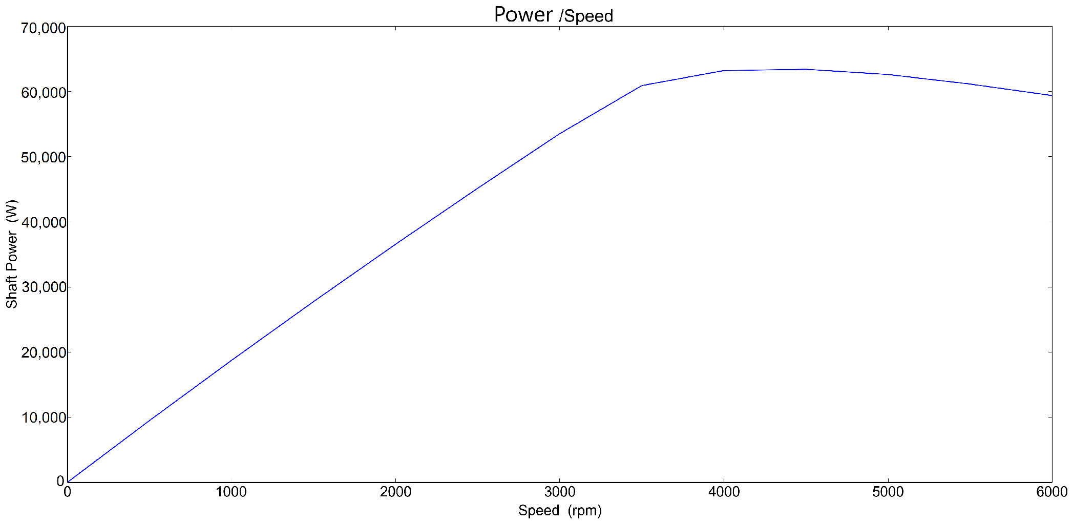
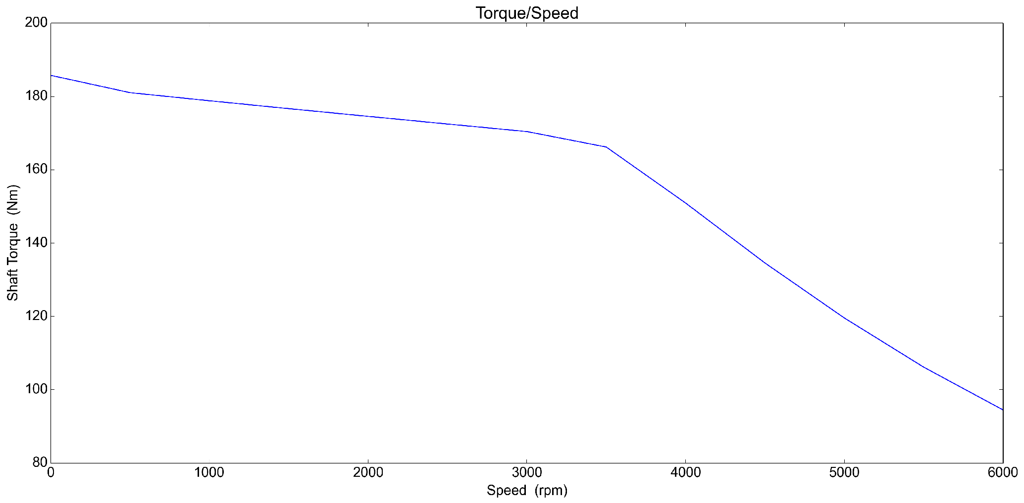
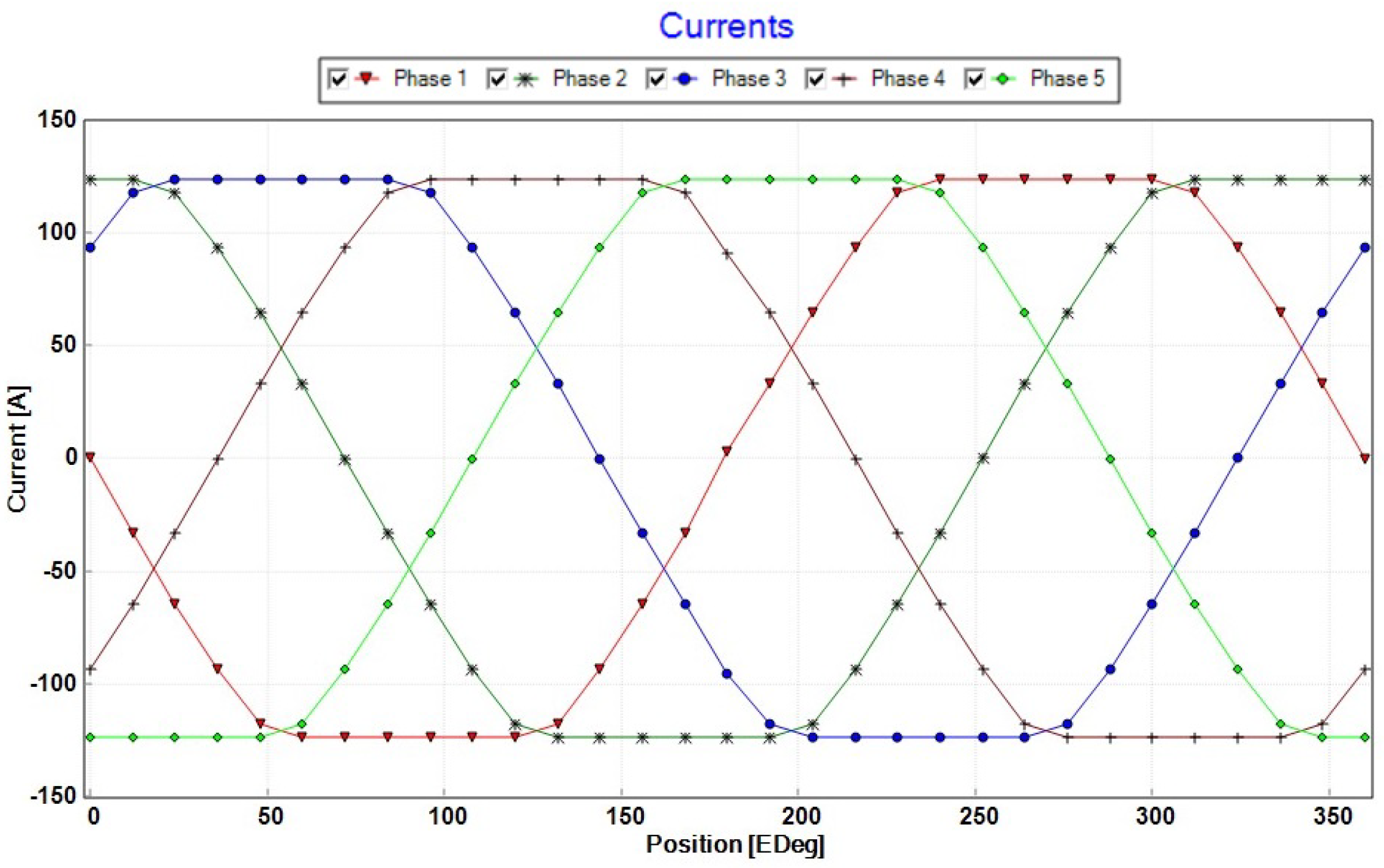
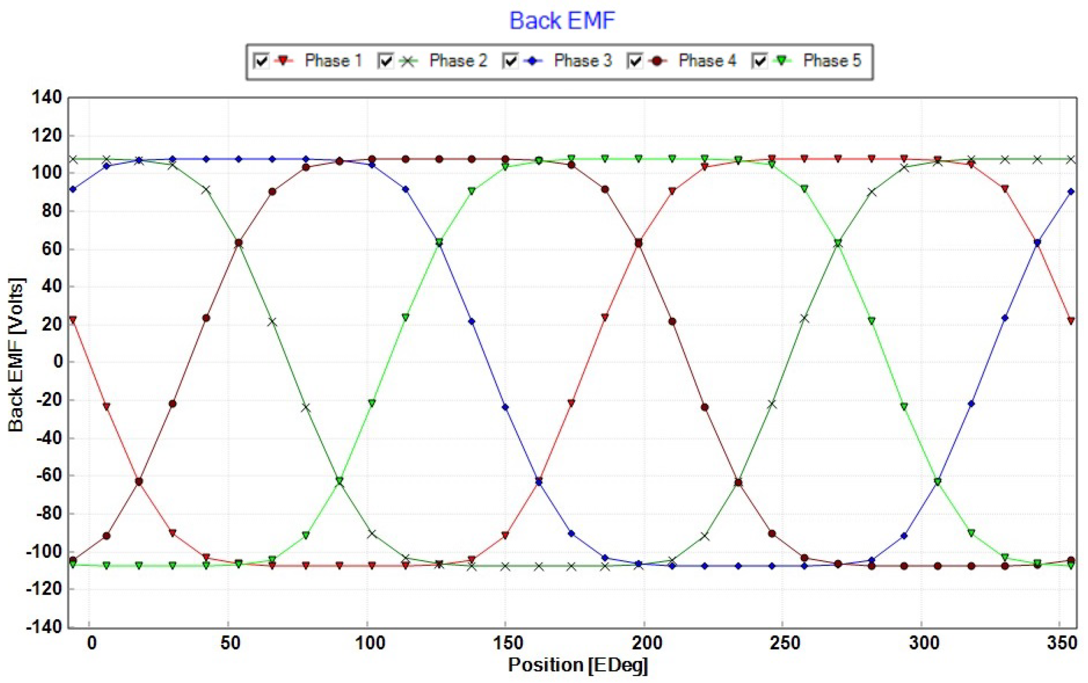
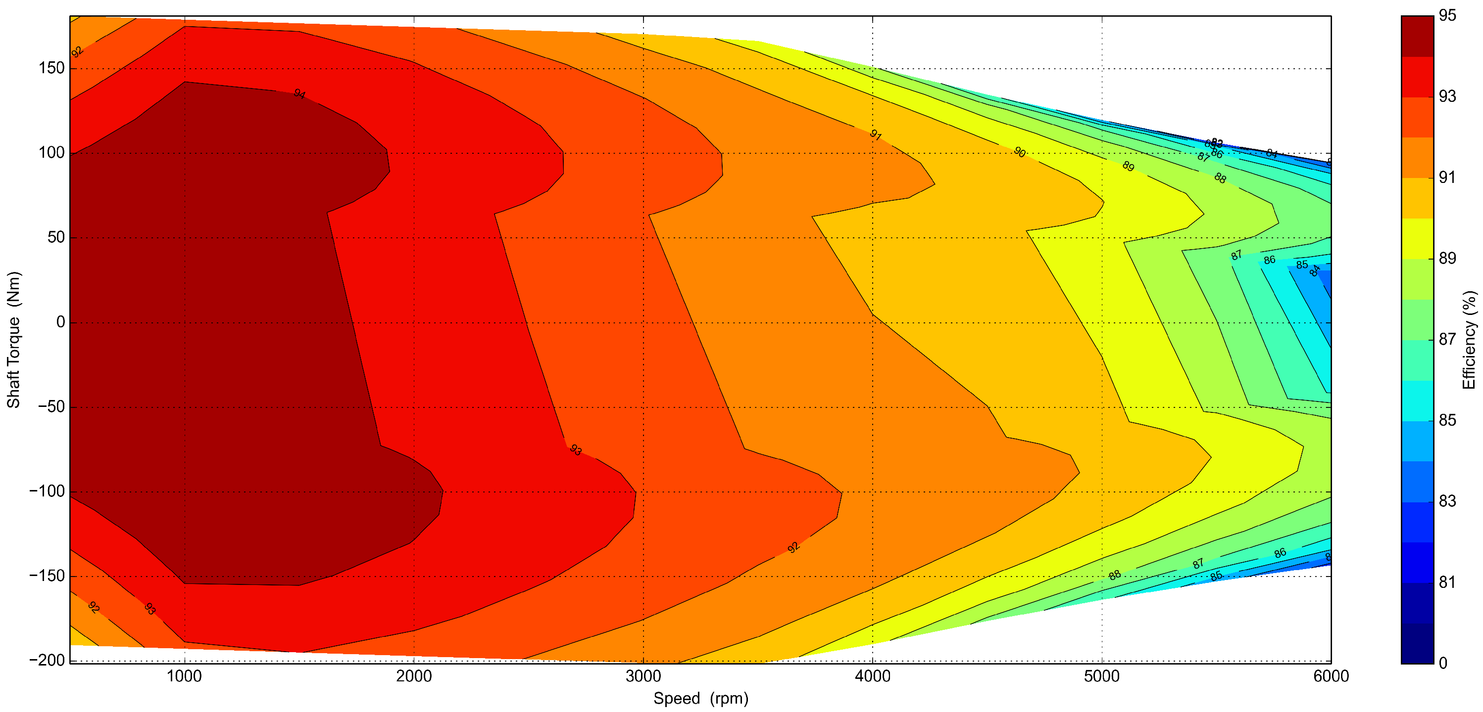
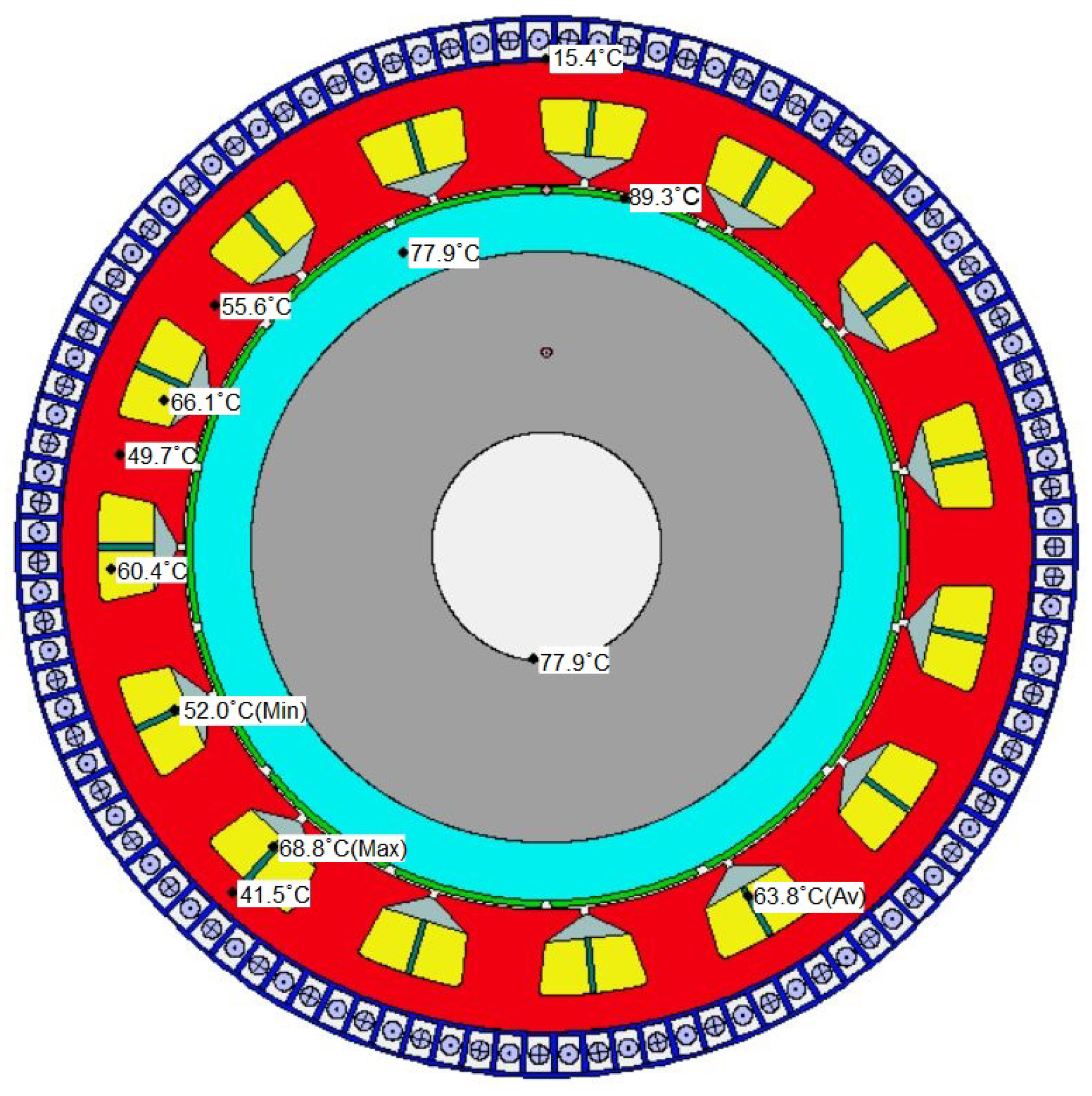
3.1. Results for Designed Five-Phase BLDC Motor

The machine parameters were determined and calculated according to magnetic flux density, phase current and air-gap flux density. In the meantime, machine torque and speed were crucial for the flight dynamics of the UAV. Because of this, these values were observed and obtained during the simulation. The simulation results of the designed motor are compared and shown in Table 7:
Table 7. Comparison of calculated values and simulation results.
The designed machine’s performance characteristics can be observed with power and torque changes against machine speed. The related changes can be observed in Figure 7 and Figure 8. According to the simulation results, shaft torque was obtained nearly to the calculated value, which can be seen in Table 7. The magnetic flux densities in the determined areas were also critical to avoiding saturation on the used material. These were selected according to the reference guide book [25], and they can be compared with the simulation results according to Table 7.
Figure 7. Power–speed characteristics of the designed motor.
Figure 8. Torque–speed characteristics of the designed motor.
The phase currents of the designed machine are shown in Figure 9, the graphic has been drawn current change against the electrical degrees for five phases.
Figure 9. Current changes in the electrical degree domain.
In addition to the phase currents, the Back-EMF changes that were created by the phase currents are shared in Figure 10. These have also been drawn against the electrical degrees for five phases.
Figure 10. Back-EMF changes in the electrical degree domain.
Losses and efficiency were further important parameters for the designed motor. In Table 6, the machine losses, which were based on copper, magnet, stator and rotor iron, are shared. In this respect, an efficiency map was created and is shown in Figure 11. This was created for both the motor and generator operation modes. The efficiency value was calculated as nearly 92% with losses, as shown in Table 8 at 2500 rpm:
Figure 11. Efficiency map of the designed motor.
Table 8. Losses for designed motor.
Thermal mapping was another important step for the motor, as it affects machine performance. Especially for magnets, temperature is important for the magnetic characteristics of the material. N42UH magnets were used for this motor, and the working point was set as nearly 90 degrees Celsius. Liquid cooling and spraying techniques were used in this machine, to cool the motor while working. EPW 50/50 was selected as the coolant. The cooling lines were located axially around the cascade. A thermal map of the motor is shown in Figure 12:
Figure 12. Thermal mapping of designed motor.

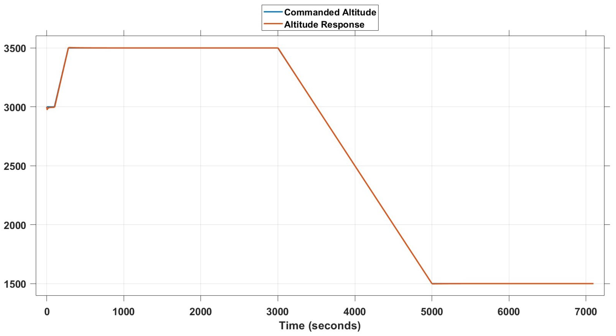
3.2. Simulation of Combined Models

As described in the sections above, a separately designed UAV model was combined and, after that, the designed machine was imported there with the system-level model. With the system-level model, the critical parameters for the UAV had been implemented, such as torque and power with desired speed and load torque. In this regard, the machine performance could be seen in the UAV model in a fast and accurate way. The results from motor implementation to the created UAV model were gathered according to the created flight profile.
In Figure 13, the altitude command and the UAV’s response is shown. The command was generated according to the flight profile, which was shared in the previous sections. The machine’s ability to provide the required torque as a response to altitude commands can be seen.
Figure 13. Altitude command and response for simulated UAV model.
In Figure 14, the created thrust power that came from the designed motor is shown. The thrust power was calculated by considering both the propeller and the mechanical component efficiencies. In addition to the propeller, other aerodynamic parameters were considered with the related calculation.
Figure 14. Created thrust power with designed motor.
Shaft torque and speed are critical parameters for creating the required thrust power to fly an aircraft. In Figure 15, the shaft power and speed changes are shown that were created by the designed motor.
Figure 15. Created machine’s shaft torque and speed changes against time.
The SoC was another critical parameter for the flight profile, because it defined the flight duration in this case. As explained before, the simulation was stopped when it reached 20% of the SoC level. Also, it can be seen in Figure 16 that energy consumption changed according to the altitude commands, which required more or less thrust to keep to the selected path.
Figure 16. SoC change rate against time.

4. Discussion

Implementing an electric propulsion system for vehicles that are powered by conventional powertrain systems is a popular topic, and many examples can be found in both the literature and in applications in real life. However, some vehicles, especially aircraft, are not completely electrified, because of regulations or current technologies. UAVs are a type of aircraft, and their proportion of usage is growing larger in both military and civil applications. Some of them still use conventional propulsion systems because of their range and endurance capability. Current battery technology cannot meet the desired duration. In addition, presented topology in the study is novel for MALE UAVs, and electrified propulsion systems can still be preferred, depending on the flight or mission profile. In this study, a MALE UAV was selected to implement an electric propulsion system, and its impact was assessed. With this purpose, a currently used aircraft was selected and a newly designed electric motor was implemented. Its only battery, which was certified for aviation, was implemented, and a basic model was created, to see the flight duration with a determined flight profile. According to the results, the UAV could fly 7067 s (1.96 h) with the proposed model. It could be preferred, based on a mission or flight profile that required these specifications. Also, another option is to create different models with different amounts of components while avoiding violation of the MTOW. A hybrid system of propulsion could be considered as future work, as an enhancement of the designed electric propulsion system.

5. Conclusions

In this study, an electric motor design processes was shown, with graphical and tabulated data. Also, a performance analysis of a UAV, which was powered by a designed propulsion system, was conducted. It was shown that the designed motor had 92% efficiency. This could affect operation costs directly. The created motor was designed with five phases that made it fault-tolerant, which means that it can be operated even if there is a failure with one or two of the terminal phases. In addition, we observed that with the deployed model the electric propulsion system, which was simply modeled, could achieve an approximately 2 h operation. When compared to the ICE propulsion system, the proposed full electric propulsion system offers several advantages, despite a shorter operational duration per charge: it is more silent, more efficient and does not emit hazardous gases into the air. Additionally, it is expected to be cost-effective compared with gasoline prices and electric charging prices for a 2 h operation. It provides a more reliable and fault-tolerant operation with the multi-phase designed machine, as mentioned before. A multi-phase electric motor can still be operative, even if it loses one or two of its terminal phases in a case of malfunction. Conversely, there is no possibility of operating an ICE if there is a fault in it. In these respects, our design could be feasible for silent, environmentally friendly and cost-effective operations. This structure of propulsion system could be changed with different components and their arrangements in a UAV. This could lead other studies to enhance the performance of electric propulsion systems.

Author Contributions

E.K., A.Y.A., F.K.A. and I.S. conducted research in the literature, designed an electric machine and implemented it in a modeled aircraft, to evaluate the effects of a designed propulsion system. After the design process, a simulation was run, and all the results were analyzed. This manuscript was created according to our evaluation of the results. All authors have read and agreed to the published version of the manuscript.

Funding

This research received no external funding.

Institutional Review Board Statement

Not applicable.

Data Availability Statement

The data used and/or analyzed during the current study are available from the corresponding author on reasonable request.

Conflicts of Interest

The authors declare no conflicts of interest.

Abbreviations

The following abbreviations are used in this manuscript:
MEAMore Electric Aircraft
AEAAll Electric Aircraft
UAVUnmanned Aerial Vehicle
ICEInternal Combustion Engine
MALEMedium-Altitude Long Endurance
DCDirect Current
BLDCBrushless DC
DoFDegrees of Freedom
ftfeet
rpmrevolutions per minute
AAmpere
NmNewton Meter
TTesla
VVolt
AhAmpere-hour
WWatt
kWkilo-Watt
kgkilogram
m/smeters per second
mmmillimeter
SoCState of Charge
MTOWMaximum Take-Off Weight

References

  1. Ye, X.; Savvarisal, A.; Tsourdos, A.; Zhang, D.; Jason, G. Review of hybrid electric powered aircraft, its conceptual design and energy management methodologies. Chin. J. Aeronaut. 2021, 34, 432–450. [Google Scholar]
  2. Fahimi, B.; Lewis, L.H.; Miller, J.M.; Pekarek, S.D.; Boldea, I.; Ozpineci, B.; Hameyer, K.; Schulz, S.; Ghaderi, A.; Popescu, M.; et al. Automotive Electric Propulsion Systems: A Technology Outlook. IEEE Trans. Transp. Electrif. 2023, 10, 5190–5214. [Google Scholar] [CrossRef]
  3. Milev, G. Power Quality Problems on Ships with Electrical Propulsion. In Proceedings of the 2023 15th Electrical Engineering Faculty Conference (BulEF), Varna, Bulgaria, 16–19 September 2023; pp. 1–4. [Google Scholar]
  4. Valavanis, K.P.; Vachtsevanos, G.J. Handbook of Unmanned Aerial Vehicles; Springer: Dordrecht, The Netherlands; Heidelberg, Germany; New York, NY, USA; London, UK, 2015; Volume 1. [Google Scholar]
  5. Koster, J.; Humbargar, C.; Serani, E.; Velazco, A.; Hillery, D.; Makepeace, L. Hybrid electric integrated optimized system (HELIOS)-design of a hybrid propulsion system for aircraft. In Proceedings of the 49th AIAA Aerospace Sciences Meeting Including the New Horizons Forum and Aerospace Exposition, Orlando, FL, USA, 4–7 January 2011; p. 1011. [Google Scholar]
  6. Sliwinski, J.; Gardi, A.; Marino, M.; Sabatini, R. Hybrid-electric propulsion integration in unmanned aircraft. Energy 2017, 140, 1407–1416. [Google Scholar] [CrossRef]
  7. Looney, B. Statistical review of world energy, 2020. Bp 2020, 69, 66. [Google Scholar]
  8. Rakhra, P.; Norman, P.; Galloway, S.; Burt, G. Modelling and simulation of a mea twin generator uav electrical power system. In Proceedings of the 2011 46th International Universities’ Power Engineering Conference (UPEC), Soest, Germany, 5–8 September 2011; pp. 1–5. [Google Scholar]
  9. Zhang, G.; Ma, C.; Sun, H.; Zhang, L.; Liu, L.; Wang, K. Optimization design of interior PM starter-generator. In Proceedings of the 2017 20th International Conference on Electrical Machines and Systems (ICEMS), Sydney, Australia, 11–14 August 2017; pp. 1–5. [Google Scholar]
  10. Fugaro, F.; Palmieri, M.; Cascella, G.L.; Cupertino, F. Aeronautical hybrid propulsion for More Electric Aircraft: A case of study. In Proceedings of the 2018 AEIT International Annual Conference, Bari, Italy, 3–5 October 2018; pp. 1–6. [Google Scholar]
  11. Donateo, T.; De Pascalis, C.L.; Ficarella, A. Synergy effects in electric and hybrid electric aircraft. Aerospace 2019, 6, 32. [Google Scholar] [CrossRef]
  12. Arabul, A.Y.; Kurt, E.; Keskin Arabul, F.; Senol, İ.; Schrötter, M.; Bréda, R.; Megyesi, D. Perspectives and development of electrical systems in more electric aircraft. Int. J. Aerosp. Eng. 2021, 2021, 5519842. [Google Scholar] [CrossRef]
  13. Kaynak, B.; Arabul, A.Y. Aerodynamic Efficiency and Performance Development in an Electric Powered Fixed Wing Unmanned Aerial Vehicle. Electr. Power Components Syst. 2023, 51, 724–732. [Google Scholar] [CrossRef]
  14. Zhang, B.; Song, Z.; Zhao, F.; Liu, C. Overview of propulsion systems for unmanned aerial vehicles. Energies 2022, 15, 455. [Google Scholar] [CrossRef]
  15. Singhal, G.; Bansod, B.; Mathew, L. Unmanned Aerial Vehicle Classification, Applications and Challenges: A Review. Preprints 2018. [Google Scholar] [CrossRef]
  16. Çoban, S.; Oktay, T. Unmanned Aerial Vehicles (UAVs) According to Engine Type. J. Aviat. 2018, 2, 177–184. [Google Scholar] [CrossRef]
  17. Xiao, C.; Wang, B.; Zhao, D.; Wang, C. Comprehensive investigation on Lithium batteries for electric and hybrid-electric unmanned aerial vehicle applications. Therm. Sci. Eng. Prog. 2023, 38, 101677. [Google Scholar] [CrossRef]
  18. Sahoo, S.; Zhao, X.; Kyprianidis, K. A review of concepts, benefits, and challenges for future electrical propulsion-based aircraft. Aerospace 2020, 7, 44. [Google Scholar] [CrossRef]
  19. Sziroczak, D.; Jankovics, I.; Gal, I.; Rohacs, D. Conceptual design of small aircraft with hybrid-electric propulsion systems. Energy 2020, 204, 117937. [Google Scholar] [CrossRef]
  20. González-Espasandín, Ó.; Leo, T.J.; Navarro-Arévalo, E. Corrigendum to “Fuel Cells: A Real Option for Unmanned Aerial Vehicles Propulsion”. Sci. World J. 2015, 2015, 419786. [Google Scholar] [CrossRef] [PubMed]
  21. Dantsker, O.D.; Caccamo, M.; Imtiaz, S. Electric propulsion system optimization for long-endurance and solar-powered unmanned aircraft. In Proceedings of the 2019 AIAA/IEEE Electric Aircraft Technologies Symposium (EATS), Indianapolis, IN, USA, 22–24 August 2019; pp. 1–24. [Google Scholar]
  22. Barrero, F.; Duran, M.J. Recent advances in the design, modeling, and control of multiphase machines—Part I. IEEE Trans. Ind. Electron. 2015, 63, 449–458. [Google Scholar] [CrossRef]
  23. Cavagnino, A.; Li, Z.; Tenconi, A.; Vaschetto, S. Integrated generator for more electric engine: Design and testing of a scaled-size prototype. IEEE Trans. Ind. Appl. 2013, 49, 2034–2043. [Google Scholar] [CrossRef]
  24. Iftikhar, M.H.; Park, B.G.; Kim, J.W. Design and analysis of a five-phase permanent-magnet synchronous motor for fault-tolerant drive. Energies 2021, 14, 514. [Google Scholar] [CrossRef]
  25. Pyrhonen, J.; Jokinen, T.; Hrabovcova, V. Design of Rotating Electrical Machines; John Wiley & Sons Ltd.: Chichester, UK, 2013. [Google Scholar]
  26. Hendershot, J.R.; Miller, T.J.E. Design of Brushless Permanent-Magnet Motors; Oxford University Press: Oxford, UK, 1995. [Google Scholar]
  27. Forces, U.S.A. MQ-1B Predator. 2015. Available online: https://www.af.mil/About-Us/Fact-Sheets/Display/Article/104469/mq-1b-predator/ (accessed on 28 April 2024).
  28. Vukelich, S.R.; Williams, J.E. The USAF Stability and Control Datcom Volume I, Users Manual McDonnell Douglas Astronautics Company St. Louis Division Public Domain Aeronautical Software. 1999. Available online: https://www.pdas.com/datcomrefs.html (accessed on 15 January 2023).
  29. Turevskiy, A.; Gage, S.; Buhr, C. Model-based design of a new light-weight aircraft. In Proceedings of the AIAA Modeling and Simulation Technologies Conference and Exhibit, Hilton Head, SC, USA, 20–23 August 2007; p. 6371. [Google Scholar]
  30. Frye, A.J.; Mehiel, E.A. Modeling and simulation of vehicle performance in a UAV swarm using horizon simulation framework. In Proceedings of the AIAA SciTech 2019 Forum, San Diego, CA, USA, 7–11 January 2019; p. 1980. [Google Scholar]
  31. Pipistrel. Pipistrel Velis Electro Pilot’s Operating Handbook; POH-128-00-40-001, Rev:0; Pipistrel: Ajdovščina, Slovenia, 2020. [Google Scholar]
Disclaimer/Publisher’s Note: The statements, opinions and data contained in all publications are solely those of the individual author(s) and contributor(s) and not of MDPI and/or the editor(s). MDPI and/or the editor(s) disclaim responsibility for any injury to people or property resulting from any ideas, methods, instructions or products referred to in the content.

Article Metrics

Citations

Article Access Statistics

Multiple requests from the same IP address are counted as one view.