1. Introduction
Cities face significant acoustic pollution primarily stemming from traffic, affecting a large portion of the population [
1]. The widespread adoption of electric and hybrid vehicles globally, attributed to their environmental benefits such as reduced carbon emissions [
2], has notably reduced environmental noise due to their quieter operation, especially evident at lower speeds compared to traditional gasoline-powered vehicles [
3]. However, the absence of engine noise, once considered advantageous, now poses challenges, particularly at speeds below 10 km/h, where the disparity in noise levels becomes apparent [
4]. This absence not only contributes to an increase in accidents involving silently operating electric or hybrid vehicles but also obscures the limited noise they emit, presenting risks to pedestrians who rely on auditory cues [
5].
Acknowledging these risks, efforts have been made to enhance the detectability of electric and hybrid vehicles [
6]. Sekine et al. found in their study involving 40 participants, including 15 visually impaired individuals, that the majority were unable to detect the presence of silent vehicles traveling below 10 km/h [
7]. To address these safety concerns, Japan introduced the initial guidelines for silent vehicles in 2011 [
8]. These guidelines underwent revisions and updates, ultimately leading to the publication of the CEPE No. 138 regulation in 2017, coinciding with the development of various warning systems [
9]. This regulation mandates the installation of an Acoustic Vehicle Alert System (AVAS), which generates sound to alert pedestrians of approaching vehicles within the 0–20 km/h speed range, with specific criteria outlining sound levels and frequency ranges.
The preference for natural and clear sounds stems from their pleasing acoustic qualities. However, these sounds often do not align with vehicle characteristics and require customization. It is advisable to construct the sound concept based on layout-oriented sound components, allowing for adjustments in the driving sound frequency based on the current vehicle or engine speed. In the development of Acoustic Vehicle Alert Systems (AVAS), appealing sounds need to be crafted and integrated into an in-car application. This necessitates finding a suitable software and hardware solution, such as an Electronic Control Unit (ECU) equipped with adequate resources and interfaces like CAN-bus and audio output.
Once the sound design phase is finalized, the desired sound profile is integrated into the in-car application, and appropriate adjustments are made within the vehicle. The primary purpose of the designed system is to enable real-time control of driving sound, reverse gear sound, and horn sound based on control parameters communicated via the CAN-bus. These parameters, transmitted from the vehicle through the CAN-bus protocol, include ignition status, driving mode (e.g., drive, park, reverse), and speed information. The ECU processes these inputs using a microcontroller (MCU), generates the corresponding sound file, and sends it to the amplifier. The amplifier then boosts the sound and projects it through a speaker. Additionally, while generating the driving sound, the system employs a pitch shift technique to incorporate acceleration and deceleration effects based on the vehicle’s speed.
The flexibility in the AVAS development process allows for additional functionalities, such as modifying the sound during vehicle startup, system initialization, or when the battery level reaches a critical threshold. By utilizing such parameters, the ECU dynamically adjusts the sound settings to reflect the vehicle’s condition, and the sound is emitted through external and/or internal speakers [
10].
The implementation of Acoustic Vehicle Alert Systems (AVAS) in electric and hybrid vehicles serves not only to alert pedestrians and other road users of impending danger but also to provide clear indications of the vehicle’s driving status and its approach, presence, and departure [
10]. Consequently, the artificial engine sound’s frequency should dynamically shift in correlation with the vehicle’s speed, replicating the characteristic change in noise levels associated with speed. However, the emitted sound should maintain a minimum level to ensure audibility, particularly in high-noise environments. According to ISO 10844 standards, this minimum level is defined as 50 dBA at 10 km/h and 56 dBA at 20 km/h, measured 2 m from the vehicle’s longitudinal center line to the microphone positions [
9]. Moreover, the sound emitted by a vehicle equipped with AVAS should not exceed 75 dBA under these test conditions.
Research on AVAS and warning sounds has explored various angles, including strategies to minimize noise pollution through directional guidance and assessing the environmental impact of generated sounds [
11,
12,
13]. Redirecting warning sounds has been investigated as a means to control noise pollution, with techniques such as directing sound propagation towards the vehicle’s direction of movement or pedestrian areas showing promise in reducing audibility while lowering noise levels. Several methods, including highly directional parametric speakers, low-cost speakers, and speaker arrays capable of targeted sound direction, have been proposed [
14,
15,
16,
17,
18]. However, the adoption of more sophisticated sound direction solutions has been hindered by high production and maintenance costs.
Another consideration is the susceptibility of sensitive speakers to adverse environmental conditions like wind, dust, water, and temperature fluctuations [
19]. To address this, conventional speakers can be replaced with inertial actuators, which vibrate attached structures to emit sound. Actuator-based systems can match the directivity performance of traditional speaker arrays without requiring structural modifications, as they can be connected to existing vehicle panels. However, systems using actuators may exhibit erratic frequency responses.
The automotive industry’s growing reliance on Electronic Control Units (ECUs) and integrated systems has led vehicle manufacturers to seek more sophisticated warning sounds. Consequently, there is a shift towards employing algorithms capable of generating programmable sound waves to enhance and optimize in-car audio systems.
This paper delves into the development of a graphical user interface (GUI) utilizing the Python-based HornSoundGeneratorGUI class and the Tkinter library. Moreover, it explores the design and testing of warning sounds to ensure compliance with regulations, notably ECE R28 [
20]. Through the practical and user-friendly designs facilitated by Python libraries, users can craft distinctive sounds by manipulating fundamental frequencies, harmonic value ranges, and amplitude parameters. The software offers features such as visualizing the frequency spectrum with FFT (Fast Fourier Transform) graphs, audio playback, and saving in WAV (Waveform Audio File Format) format. With its intuitive interface and flexibility in sound design, this software emerges as a valuable tool for individuals seeking to create original horn sounds.
To date, there seems to be a lack of research in the literature specifically focused on the production of digital horn sounds. Additionally, studies examining digital horn sounds generated by AVAS devices are scarce. In current AVAS products with digital horn sounds, sound production is usually managed by sound engineers who apply traditional music theory and mathematical principles. This study presents a new approach, utilizing software with oscillator and equalizer functions to generate digital horn sounds while still following traditional methods. This innovative approach is one of the main contributions of this research.
Section 2 provides a detailed explanation of the proposed structure, operational principles, and the designed interface.
Section 3 presents simulation and experimental results concerning the design and validation of sounds with frequency values of 400 and 500 Hz. Finally,
Section 4 presents the conclusion and findings of the study.
2. Recommended Topology and Working Principles
The function
that presents the horn sound based on specified parameters, adhering to a defined frequency and amplitude profile is given in (1). This is crucial for delivering precise alerts to both drivers and other road users.
In the given equation, the variable
denotes the harmonic number,
denotes the sound frequency,
represents the sampling frequency, and
represents the octave. When generating the sound, the amplitude is modulated using a fundamental sine waveform [
21]. Nevertheless, to achieve a natural and harmonically rich tone in the sound, additional harmonics are incorporated into this fundamental sine waveform. Here, the adjustment of amplitude is tailored based on the number of harmonics. In essence, the sound texture is enhanced by assigning distinct amplitude values to each of these harmonics.
Each of the first 16 harmonics, commencing with the note C2, is accompanied by its nearest musical note as shown in
Figure 1. Additionally, the disparity (measured in cents) between the frequency of a harmonic and the central frequency of the closest note is displayed at the top.
In music theory [
22], the concept of octaves holds significant relevance in the process of amplitude adjustment. In music, an octave signifies a doubling of the frequency. When modifying amplitudes in this program, harmonic frequencies rise proportionally across octaves. Specifically, the utilization of the 12-step octave structure aids in maintaining the coherence and consonance of the sound.
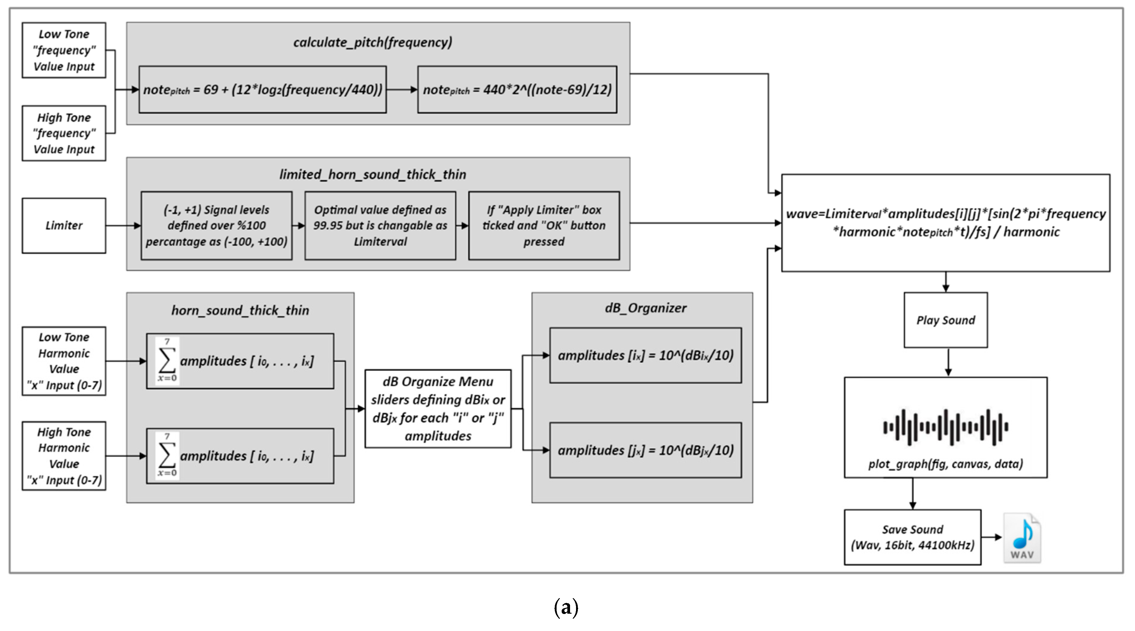
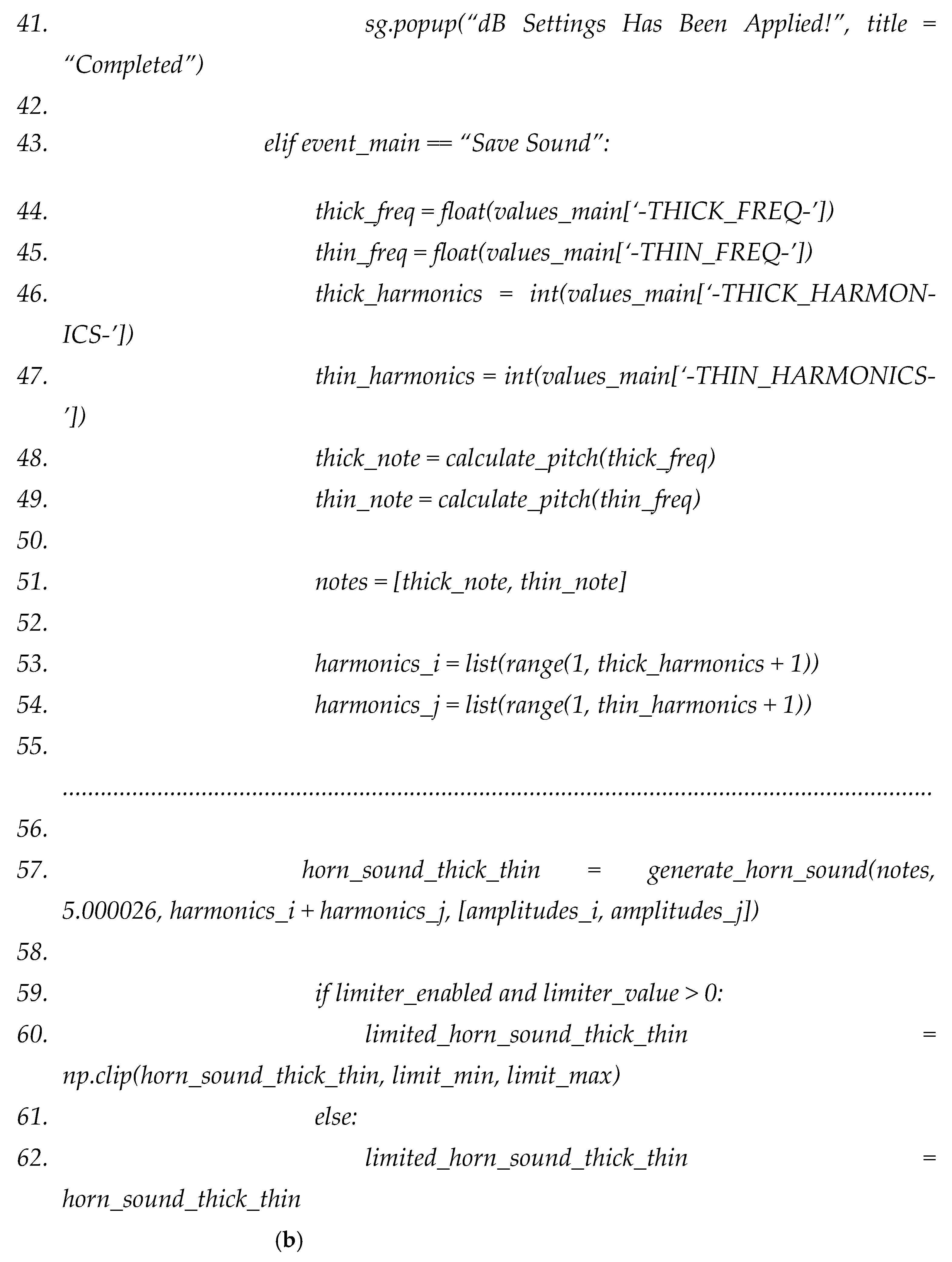
Figure 2a presents the proposed block diagram for the horn sound generator system.
Figure 2b displays the suggested corresponding Python code for the blocks in the diagram. Below is an explanation of the block diagram, the code functionality, and the definitions of the functions used.
From here, the
function within the software embodies a mathematical formula that translates frequency into a musical note value, as depicted in (2).
The octave (notepitch) detection formula identifies the musical note corresponding to any frequency by measuring its deviation from the 440 Hz reference frequency. This method offers a straightforward interpretation of the frequency’s placement within conventional musical notation.
For instance, consider note A5 with a frequency of 880 Hz: note = 81 signifies that the frequency is positioned one octave higher than the reference frequency. The derived note factor is subsequently employed in the software through reverse engineering to ascertain the frequency values of both low and high-tone frequencies within each octave (Equation (2)).
This computation serves as a fundamental tool for comprehending musical organization and ascertaining the relative placements of frequencies. By employing this formula, the note factors and fundamental frequency values for both the fundamental frequency and harmonics, which are instrumental in generating the horn sounds within the framework, are established.
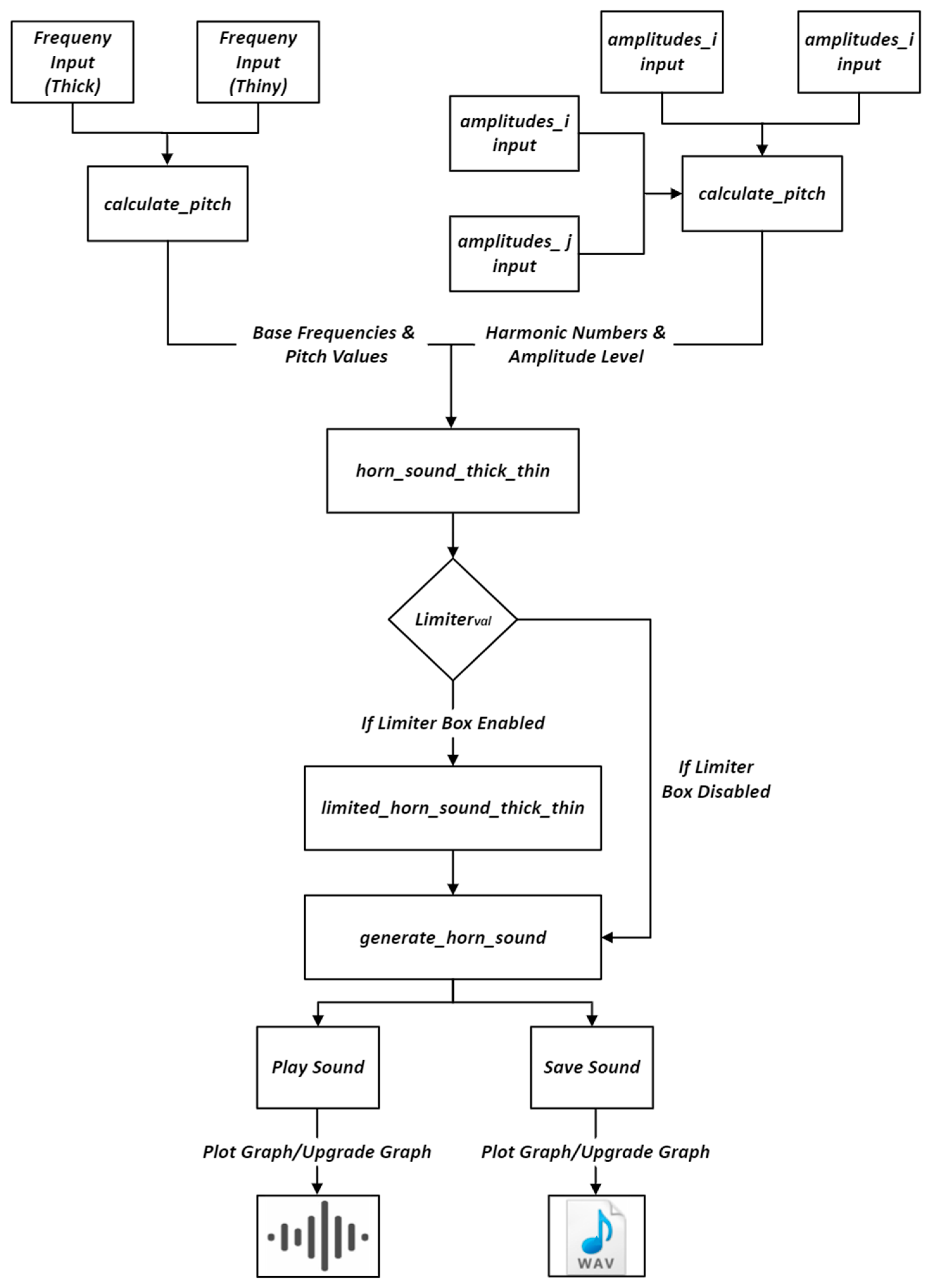
Figure 2a presents the schematic depiction of the proposed horn generator code, and
Figure 2b illustrates the suggested Python code. As depicted in
Figure 2, the
function within the software facilitates the determination of the Limiterval value. This function enables the overall management of the amplitude level of the audio signal. Its primary objective is to prevent signal saturation by imposing a specific limit on the overall amplitude level. Notably, this section is entirely optional; if the frequency-based amplitude levels are meticulously designed to harmonize without reaching saturation, the inclusion of a limiter becomes unnecessary (refer to
Figure 3).
In the
section, another software section mentioned in
Figure 2, amplitude values are calculated separately for two frequencies. Amplitude factors are output as a matrix of size.
In the equations above, refers to the number of harmonics, and refers to the amplitude coefficient of these harmonics. The determined harmonic values are streamed to the function. This function is the base of the dB Organize Menu panel. The dB values determined via sliders in Equation (5) flow separately to the low-tone and high-tone matrices.
As illustrated in
Figure 3, all operations, including amplitude, note, frequency, number of harmonics, etc., converge at the
function, where specific attributes of the generated horn sound are formed. By utilizing these variables in (6), along with user-defined variations, a digital and harmonious horn sound is produced, characterized by predetermined amplitudes at specific frequencies.
The focal point of generating the horn sound lies within the
function. Structurally, the horn sound comprises two key components: the Low Sound Frequency and the High Sound Frequency. The process of crafting a horn sound involves amalgamating specific notes with harmonics. In this dual-stage process, each fundamental frequency and harmonic value corresponds to a musical note, adhering to a 12-octave structure [
21] alongside user-defined values. These elements are utilized to generate sinusoidal waves based on the fundamental sine wave structure, as is depicted in
Figure 1.
The variable denotes the harmonic assignment and is denoted as “harmonic” in the software, allowing for user customization. The sampling frequency, remains fixed at 44.1 kHz within our system. The variable shows the “frequency” variable employed in the system and represents the fundamental frequency level. signifies amplitude values, designed to be adjustable according to user preferences. The two fundamental frequency values are allocated as two distinct series, with amplitudes varying based on the number of harmonics for [i] and [j]. This empowers the user to regulate the thickness or thinness, dB loudness, and harmonic structure of the horn sound.
GUI Interface and Usage
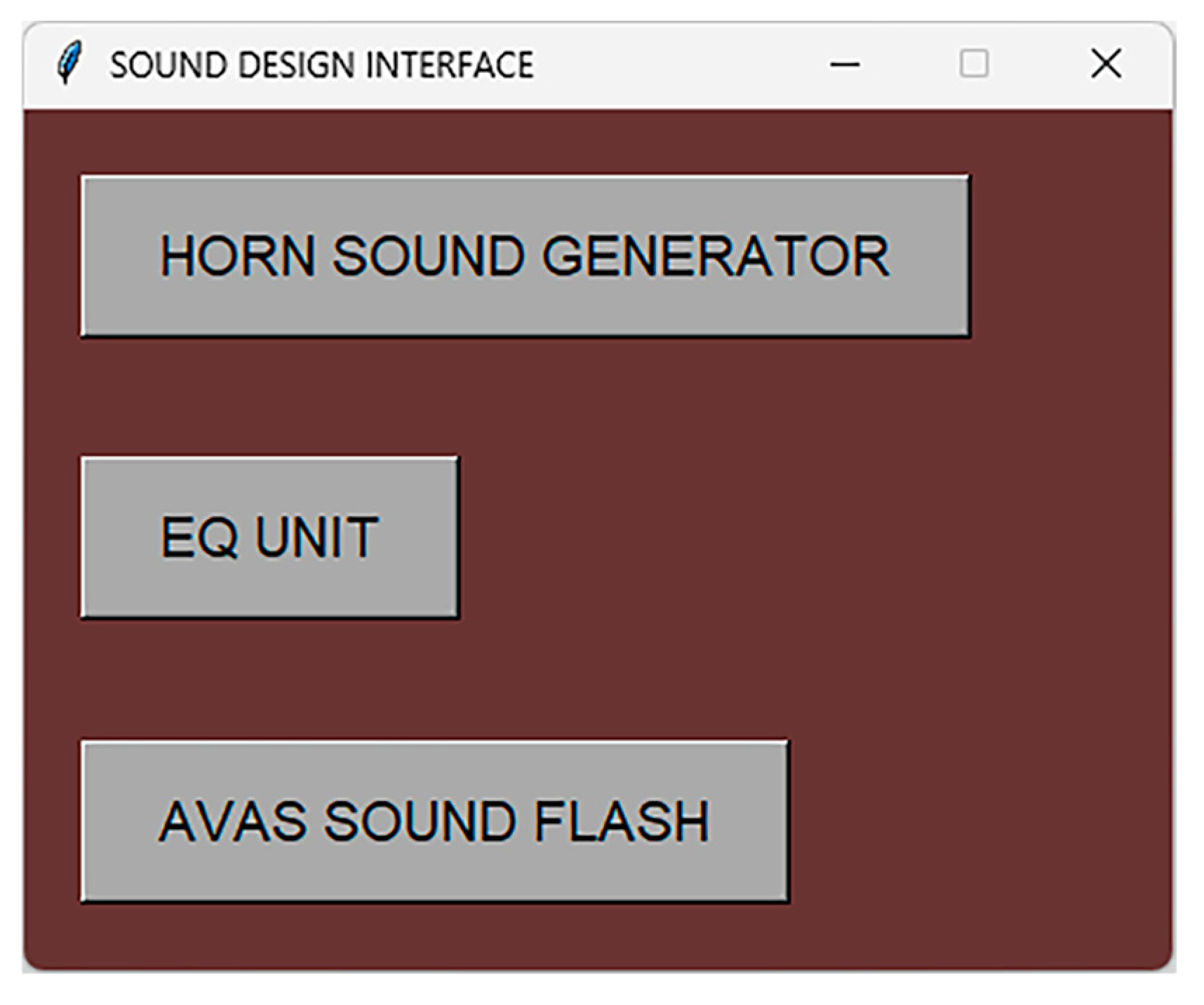
As depicted in
Figure 4, upon opening the program, users are greeted with three interfaces. Upon accessing the ‘horn sound generator’ tab, users encounter the panel of the sound generation software discussed in the article. The ‘EQ Unit’ section features a conventional equalizer system, enabling users to adjust the magnitude levels of loaded sounds within specific frequency ranges. The ‘AVAS Sound Flash’ or Audio Flashing unit converts any audio file into a format compatible with the proposed devices, ensuring adaptability and suitability.
As illustrated in
Figure 4, upon opening the program, users are presented with three distinct interfaces. Upon accessing the horn sound generator tab, users encounter the panel of the sound generation software discussed in this study. The EQ Unit section features a standard equalizer system, allowing users to adjust the magnitude levels of loaded sounds within specific frequency ranges. Additionally, the Audio Blink Unit transforms any audio file into a system compatible with the proposed devices.
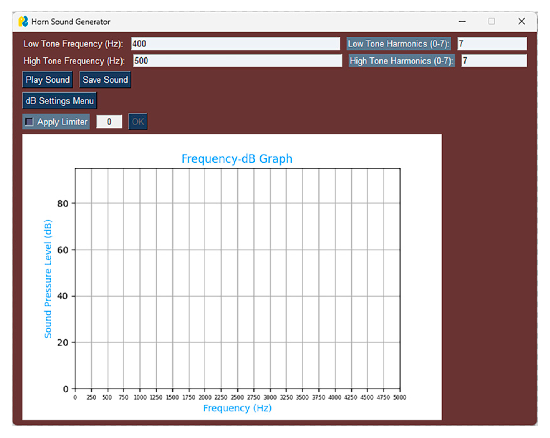
Upon entering the horn sound generation unit, users are welcomed with an interface, as depicted in
Figure 5. Sound is generated by inputting specific frequency values and harmonic numbers within this interface. Optionally, users can activate the limiter option, which operates on a percentage basis and can be assigned a value ranging from 0 to 100.
When the Play Sound button is pressed, the adjusted sound is heard immediately, and its graphic is displayed on the screen, according to
Figure 6. Pressing the Save Sound button opens a pop-up screen that allows saving the created sound in
format.
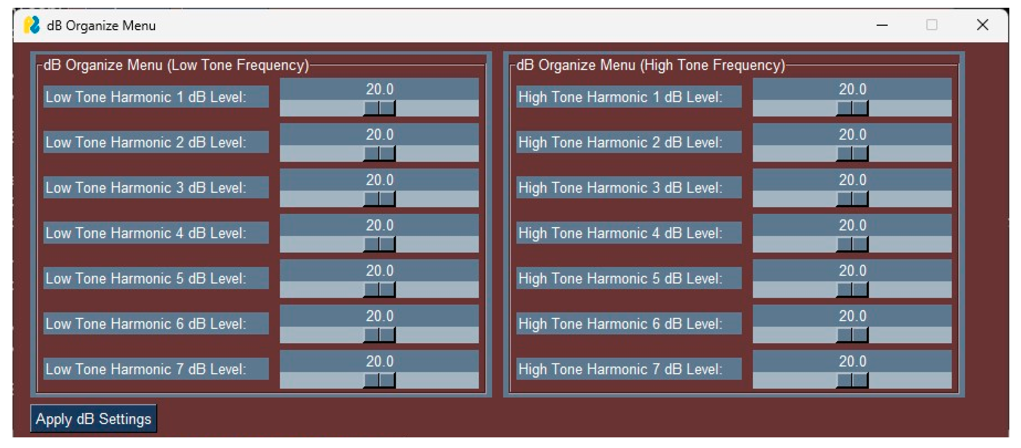
As depicted in
Figure 7, upon pressing the dB Organize Menu button, a new interface opens, featuring scroll boxes that allow for adjustment of the dB settings. Users can modify the settings using the sliders and then apply the changes by pressing the Apply dB Settings button. Subsequently, when the interface is closed, pressing the Play Sound or Save Sound buttons will generate sound with the newly edited dB settings. The GUI interface is not utilized directly within the vehicle. Instead, its output—a sound file (digital horn sound)—is stored in the memory of the AVAS device and used directly on the vehicle. Traditional methods for creating digital horn sounds require signal information, sound processing expertise, and mathematical computations, which can be time-consuming and costly. In contrast, the GUI interface streamlines the sound design and editing process, allowing unique sound outputs to be generated in just seconds. This significantly reduces both time and cost, offering substantial efficiency benefits.
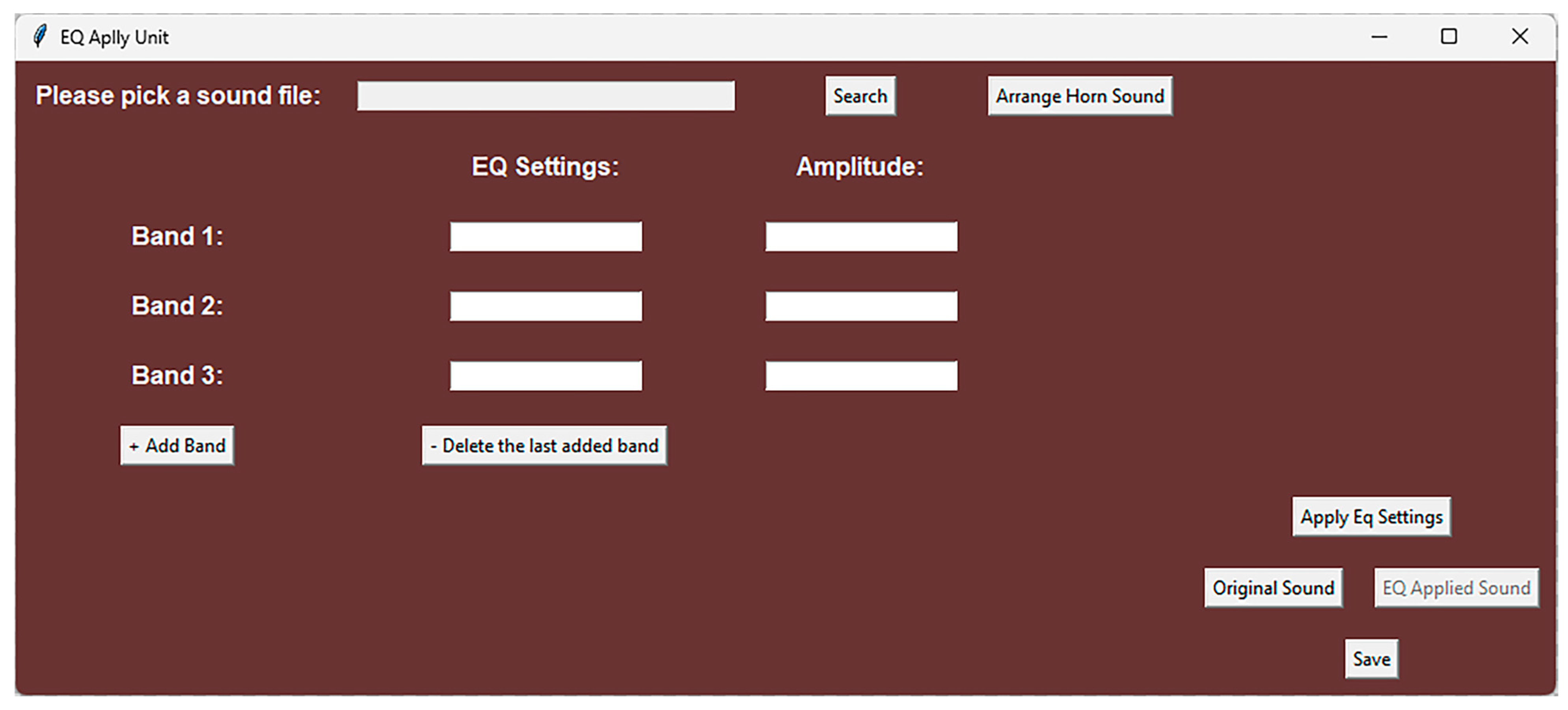
Based on
Figure 8, upon accessing the EQ Apply Unit, users encounter the displayed interface. After clicking the browse button within this interface and selecting an audio file, the relevant frequency values are entered in the Equalizer Setting sections within the Band sections. A value (either negative or positive) is then inputted in the Gain section to adjust the desired quantity. Pressing the Apply Equalizer button activates the Processed Audio feature. By clicking this button, users can listen to the audio with the equalizer applied. Additionally, pressing the Original Audio button enables users to listen to the original version of the selected audio. Lastly, clicking the Save button opens a pop-up screen, allowing users to save the synchronized audio in
format.
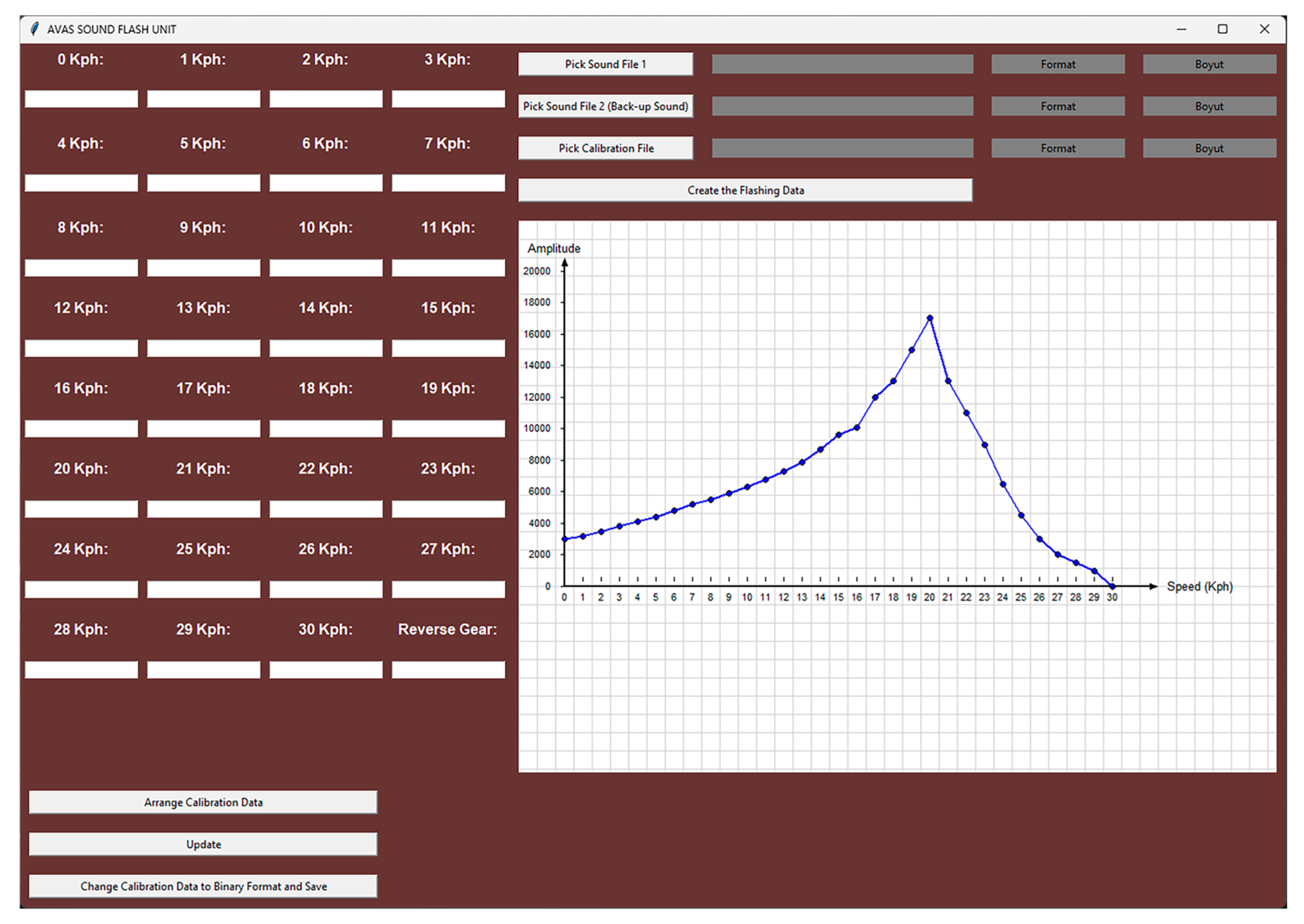
The interface of the AVAS Sound Flash Unit is displayed in
Figure 9. As previously mentioned, this interface is encrypted and accessible only to employees. Through this interface, standards can be loaded, and amplitude settings can be adjusted based on the speed levels of the selected sounds. Furthermore, users can create a file that is directly uploadable to the AVAS product. Additionally, calibration files for existing sounds can be prepared and generated using this interface.
3. Simulation and Experimental Results
The horn sound utilized in passenger vehicles typically comprises two variants: the thick horn sound (300–400 Hz) and the thin horn sound (400–500 Hz). These are associated with two types of horns: The Disc Horn and the Snail Horn. Disc Horns emit sound in the frequency range of Thick 300–320 Hz and Thin 400–420 Hz, while Snail Horns produce sound in the Thick 380–420 Hz and Thin 480–520 Hz range. Given that Digital Sounds are artificially constructed rather than derived from a natural source and possess an artificial structure, maintaining clarity at low frequencies presents a challenge. Therefore, the product design was inspired by the Snail Horn structure, and the sound structure was devised to mimic this mechanical design.
In traditional horn setups, low and high sounds are emitted by two distinct horns.
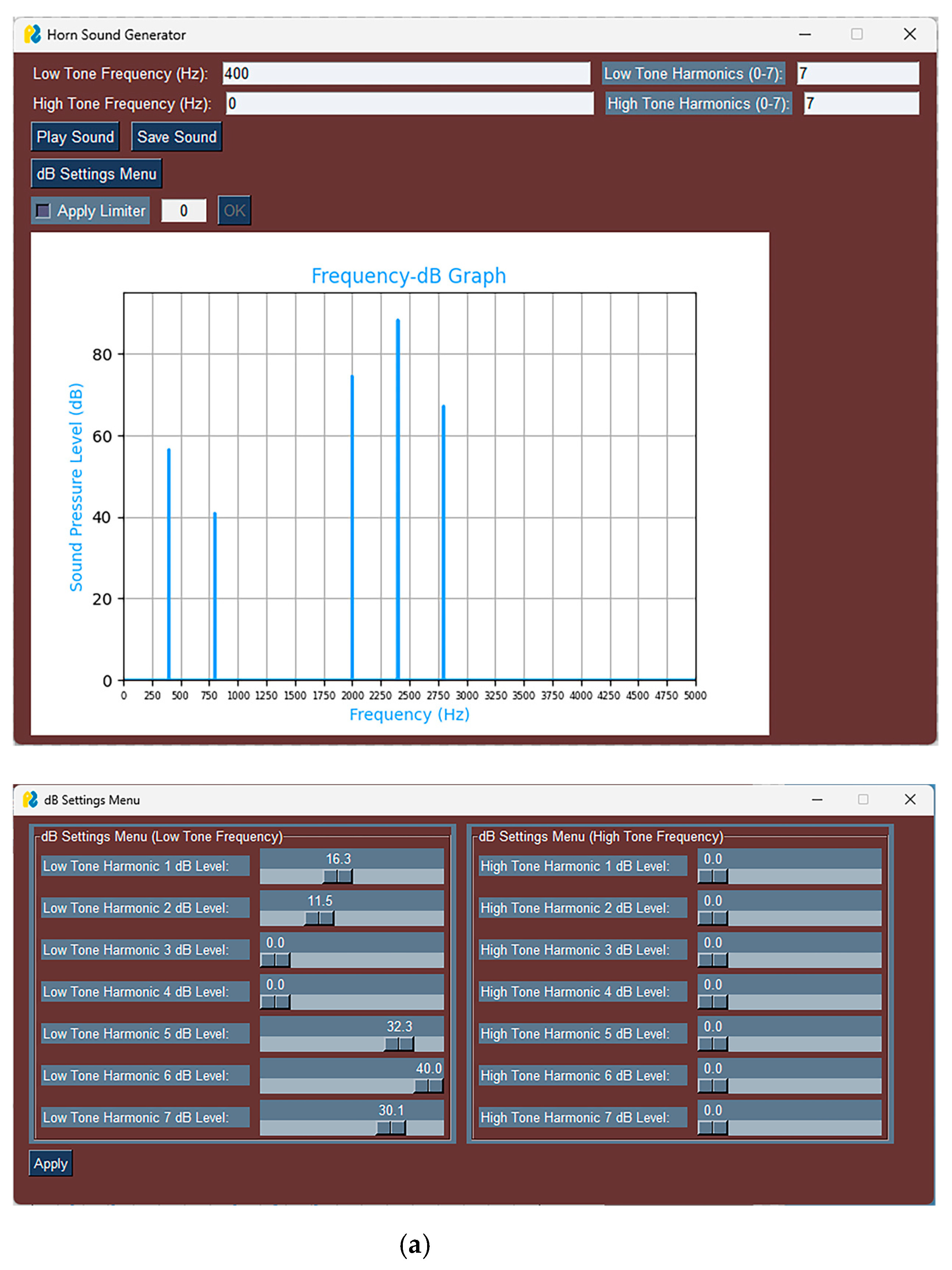
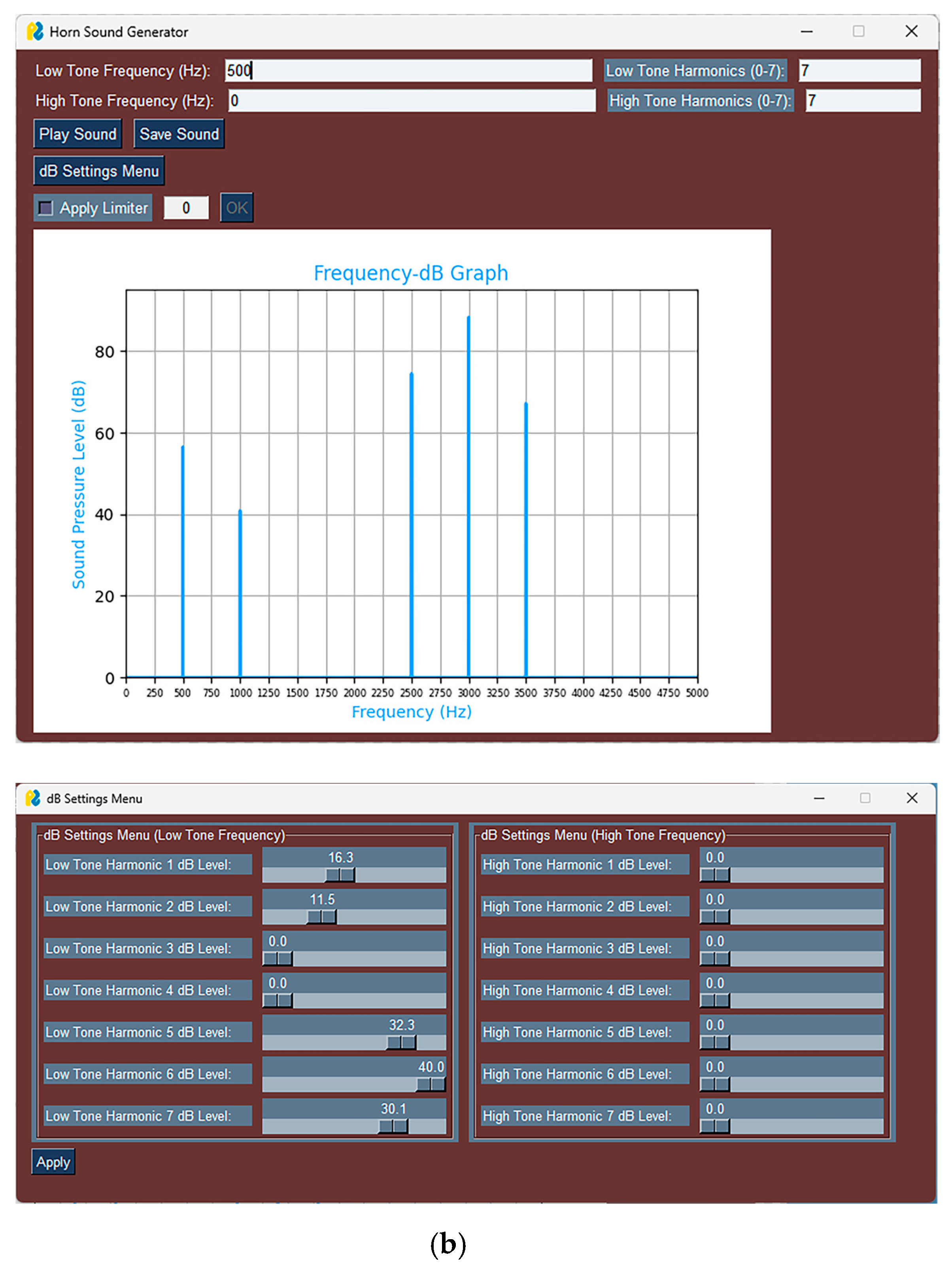
Hence, prominent digital sound arranging techniques were employed to replicate this arrangement within a Digital Mono channel sound. As shown in
Figure 8, horn sounds were generated as two distinct sounds through the Sound Control Unit program. These sounds are tailored to be 400 Hz for the Low Tone Horn and 500 Hz for the High Tone Horn.
In typical horn setups, high and low sounds are emitted by separate horns. Therefore, advanced digital sound arranging techniques were employed to replicate this arrangement within a Digital Mono channel sound. Horn sounds are generated as two distinct sounds using the SEGER Sound Control Unit program. Specifically, the sounds are tuned to be 400 Hz for the Low Tone Horn and 500 Hz for the High Tone Horn. The results are shown in
Figure 10a,b.
To mitigate interference during sound production, harmonics at specific frequencies (such as 1500 Hz and 2000 Hz) that coincide with or might clash with the harmonics of 400 Hz and 500 Hz have been attenuated. Given the preference for the deep sound to be predominant in the created sound, the attenuation process was primarily focused on the low-frequency components.
As depicted in
Figure 11, when two audio files are combined and transmitted in a single channel without any editing, the resulting signal may exhibit interference at various frequencies. Moreover, the signal in the
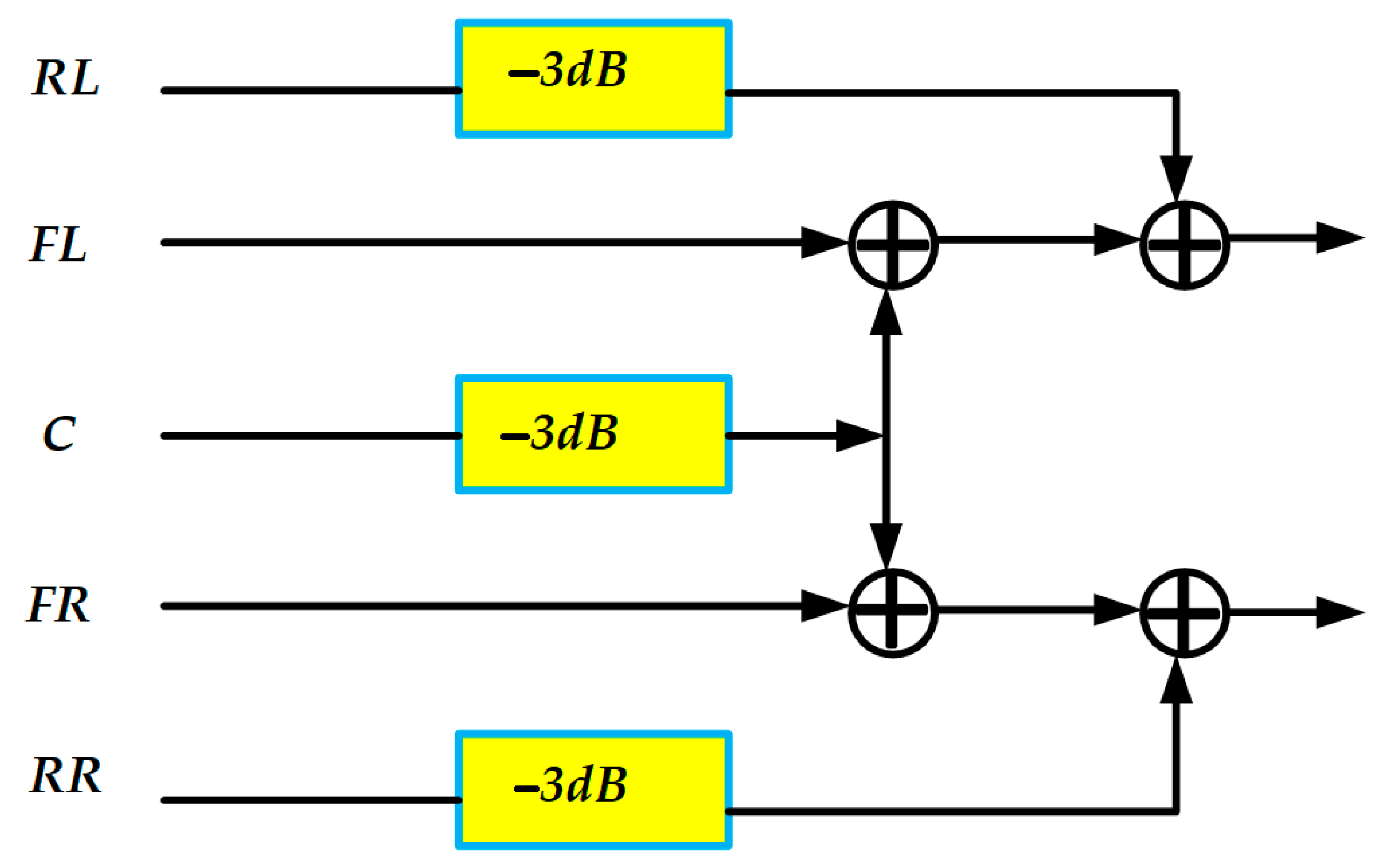
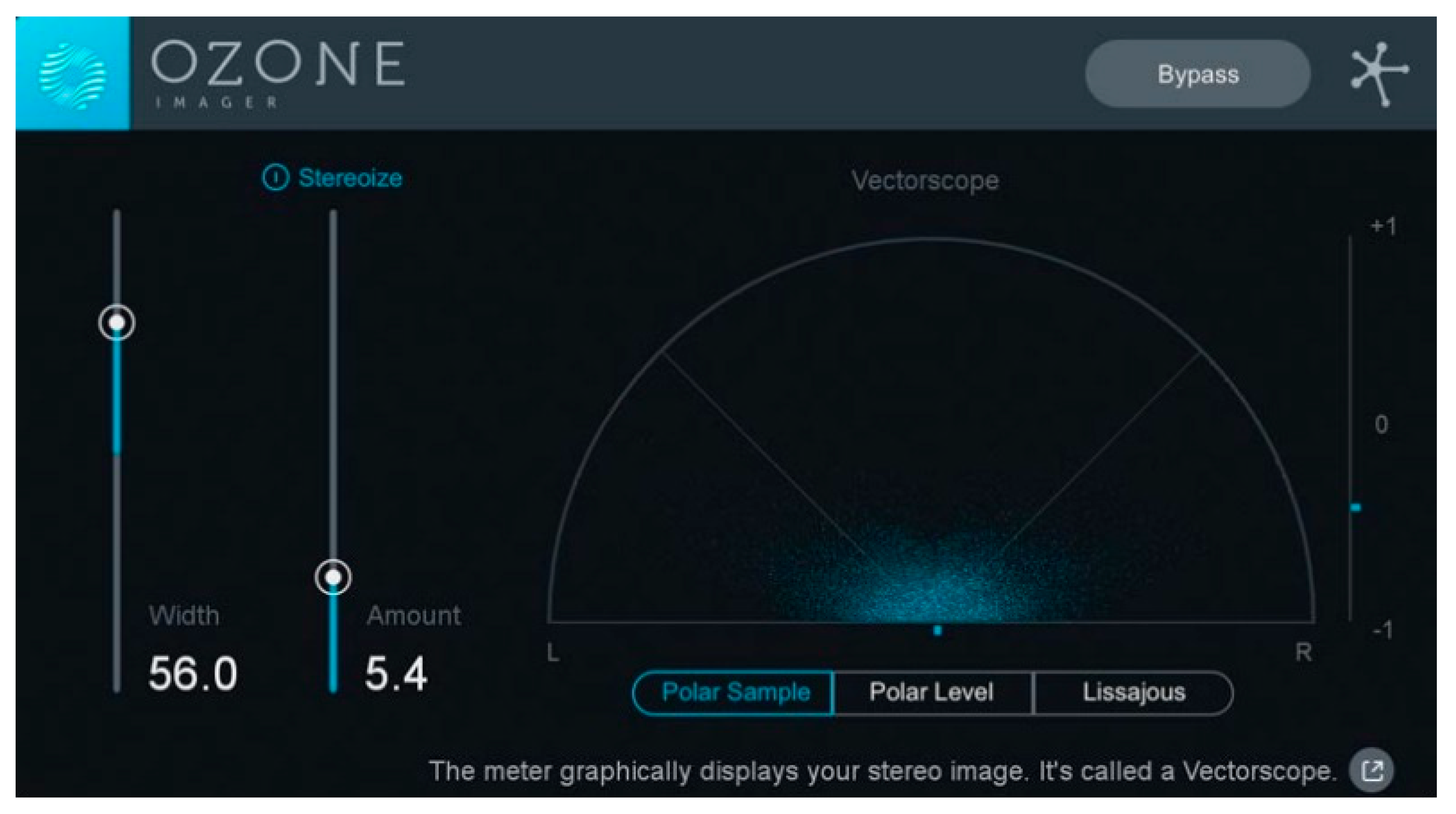
file may exceed saturation in certain regions, leading to disruption in the system. To mitigate these issues, a technique called “Channel Mixing” in digital arrangement methods was employed. Additionally, the room opening technique was utilized to impart a stereo effect to the sound within the mono channel.
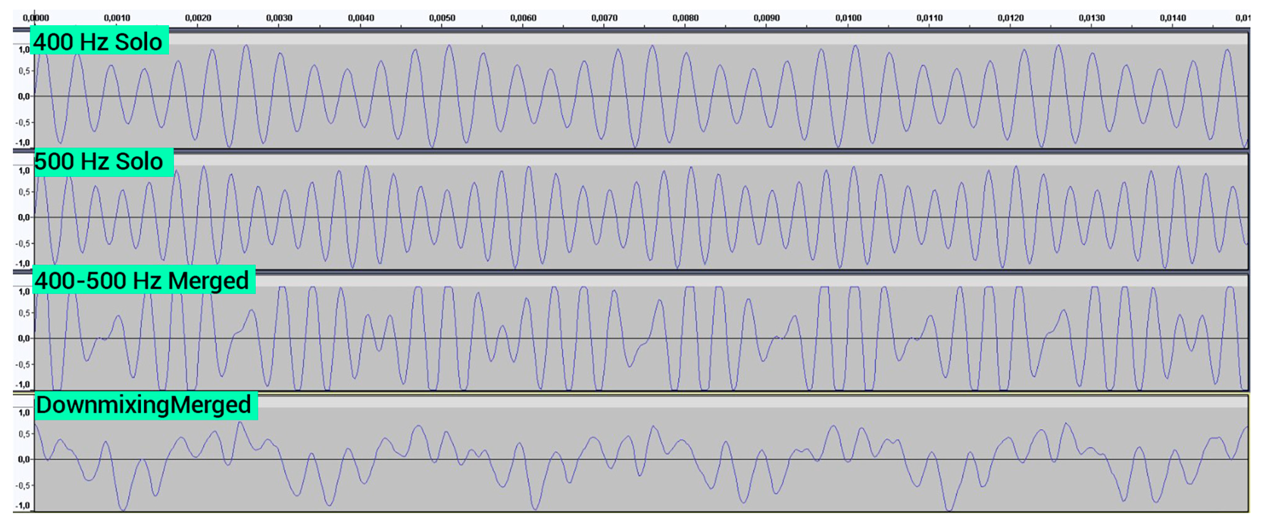
By segregating the sound into two distinct tones—namely, a low-frequency tone and a high-frequency tone—based on their fundamental frequency values
, it becomes feasible to edit the two sounds in separate channels using the Downmixing method [
23]. Subsequently, these edited sounds can be merged into a single channel, as illustrated in
Figure 12 and
Figure 13.
In
Figure 14a, first of all, adjustments were made in the frequency plane with the help of an EQ Graphic, and notch filters at a rate of 48 dB/oct were applied to the inter-harmonic regions. The aim here is to increase the dynamism of the sound by making the areas that are desired to be heard more distinct, as shown in
Figure 14b.
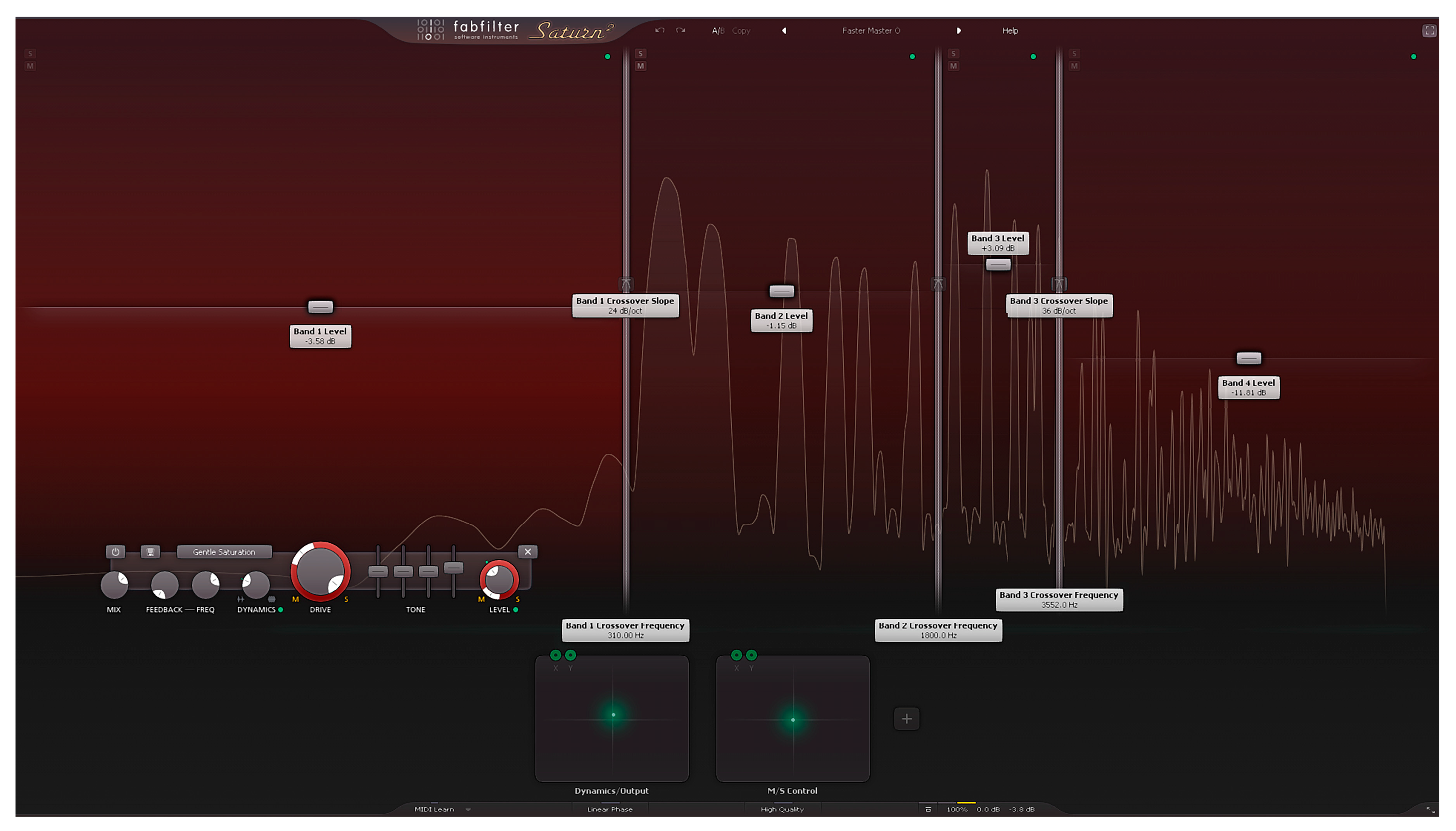
Following the configuration of settings in the Frequency plane within the audio file, adjustments were made to the dB difference between the peaks in the Significant Frequencies and the peak levels in the non-obvious range. This adjustment was carried out using a technique called Compression in Digital Arrangement processes. By employing this process, the dynamic range within the structure was regulated. Furthermore, by rendering the peaks at specific frequencies in the audio file distinguishable from one another, the sound was ensured to evoke a consistent sensation across all systems, as depicted in
Figure 15.
In
Figure 16, the single-channel audio file resulting from the arrangement operations conducted on the audio file exhibits a structurally smoother profile, effectively resolving the out-clipping problem observed in the Merge state. This arrangement guarantees that the audio file can be played as loudly and cleanly as possible across multiple systems.
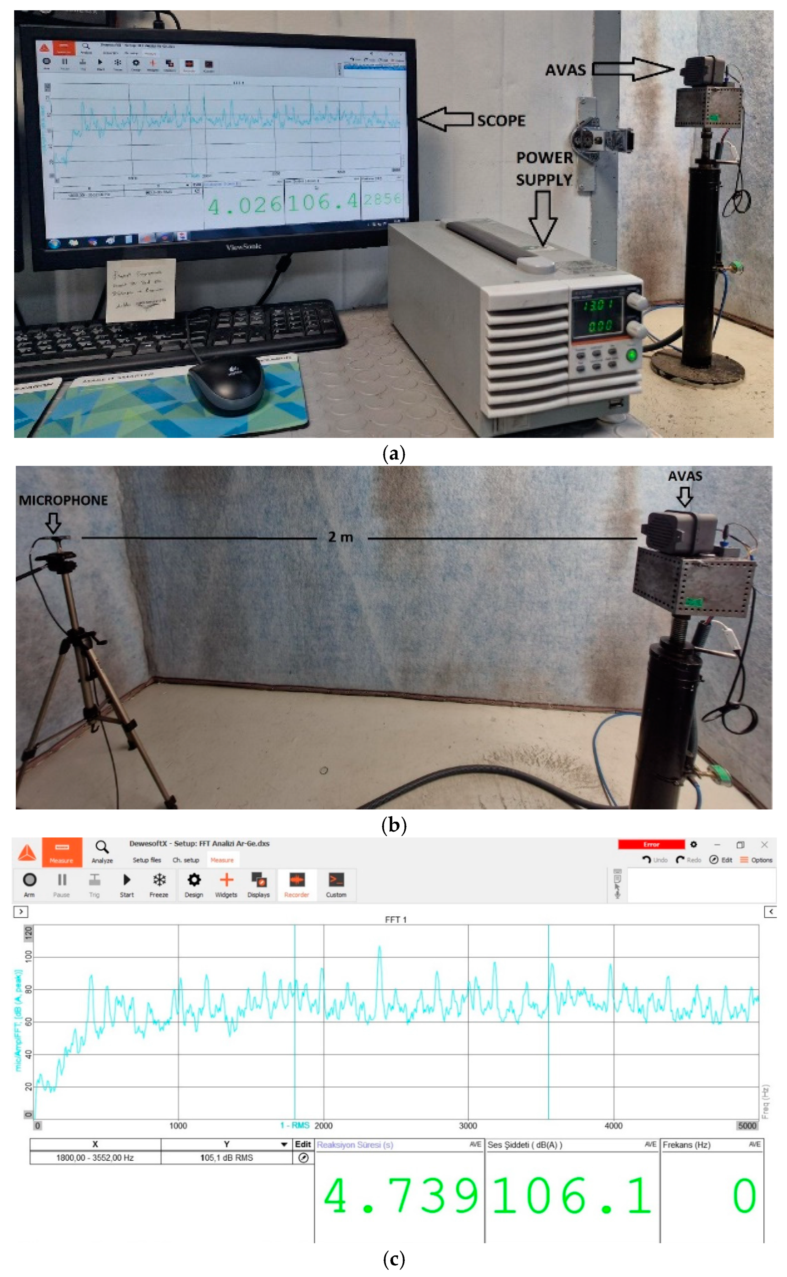
Figure 17 displays the results of computer simulations alongside the FFT graph. Furthermore, acoustic and electrical tests were conducted in a fully equipped quality laboratory to corroborate the simulation outcomes. The AVAS device, as illustrated in
Figure 18a, was connected to a DC voltage source and a calibrated acoustic test device. In
Figure 18b, the placement of the AVAS device and the measurement microphone in the sound-isolated acoustic room is depicted, maintaining a distance of 2 m, as stipulated in the regulation. Measurements were taken from this distance, revealing values ranging from 105 to 118 dB/2 m.
In
Figure 18c, the FFT graph of the AVAS system utilizing the designed digital horn sound is measured in an anechoic chamber approved by The Scientific and Technical Research Council of Türkiye, National Metrology Institute (TUBİTAK UME). It is evident from this graph that the results obtained from the simulation were also validated experimentally. Furthermore, the designed sound falls within the range specified in the regulation (106.1 dB), indicating successful compliance.
The digital horn sound obtained as a result of this study, which was tested and approved in both the simulation environment and the laboratory, is shared as a
Supplementary File under the name “Horn_Sound.wav”. The file named “Horn_Sound.wav” represents the audio output generated by the suggested program in this study, while the file named AVAS_Sound.wav corresponds to the standard AVAS sound.
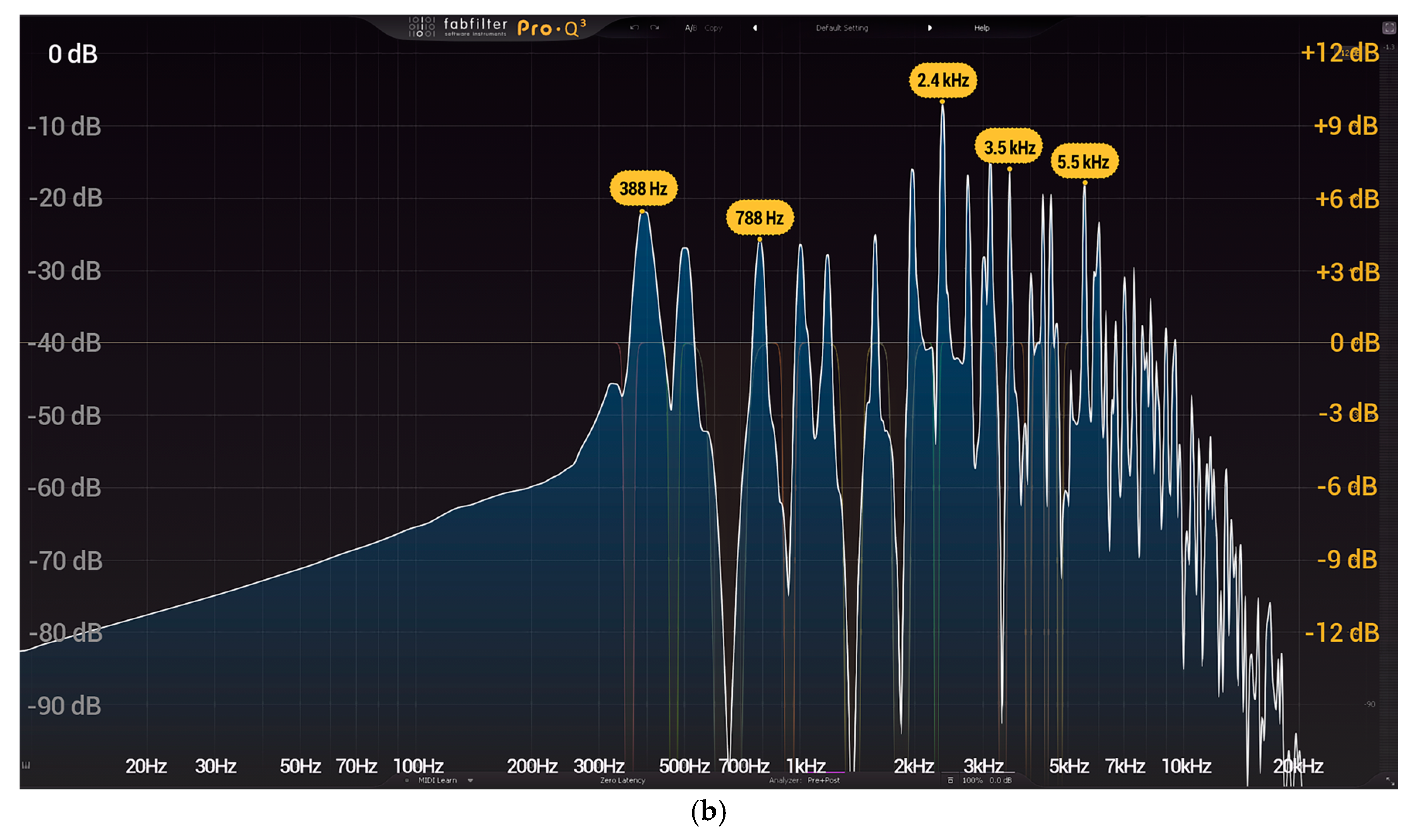
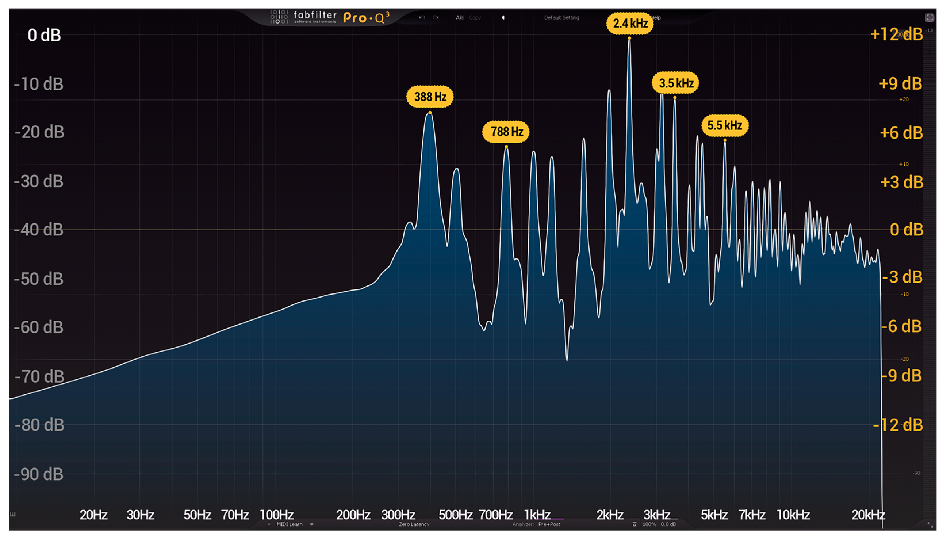
The audio signal illustrated in
Figure 19a exhibits peaks at specific frequencies with a more uniform distribution and a well-balanced tonal structure. This design ensures a cleaner and more effective sound experience, particularly in scenarios where a distinct tone is required, akin to a mechanical horn. Moreover, reduced fluctuation and noise in low-frequency regions enhance the signal’s clarity and purity, minimizing unnecessary frequency interference. The sharpness and prominence of the frequency peaks emphasize the signal’s strengths in certain frequencies, reinforcing its harmonic structure. While the audio signal in
Figure 19a benefits from careful digital design, higher dB levels, and controlled characteristics, the signal in
Figure 19b demonstrates unnecessary frequency fluctuations at lower dB levels. Consequently, the superior tonal quality and controlled structure of the signal in
Figure 19a make it the preferred choice for high-quality horn sound.
To date, there appears to be no more research in the literature specifically focused on the production of digital horn sounds. Furthermore, studies addressing digital horn sounds generated by AVAS devices are limited. In existing AVAS products featuring digital horn sounds, sound production is typically handled by sound engineers relying on traditional music theory and mathematical principles. This study introduces a novel approach, producing digital horn sounds using software equipped with oscillator and equalizer functions that adhere to traditional methods. This innovative methodology represents one of the key contributions of this study.
4. Conclusions
In traditional systems, three separate devices are required to generate the horn sound, driving sound, and reverse gear sound. This approach increases costs, vehicle volume, and weight while also complicating controllability. In contrast, the proposed system consolidates these three sound functions into a single unit, significantly reducing costs and volume. By utilizing a single ECU, the system simplifies controllability and minimizes cable complexity and power consumption on the vehicle, enhancing overall efficiency and integration. Managing warning sounds, which simulate both horn and engine sounds, through a single device offers several advantages, such as prolonged lifespan, cost-effectiveness, and easy controllability. To realize such a system, the production of digital warning sounds becomes essential.
The digital audio production software recommended in this article effectively serves the desired purpose, providing practicality and quick results with its versatile features and user-friendly interface. As horn sounds inherently possess fundamental frequencies between 300 Hz and 500 Hz, the software can generate sound within the required frequency ranges (300–500 Hz) and amplitude levels (100–107 dB). Additionally, post-production adjustments in dB/frequency can be made on the produced digital sound, and the software facilitates the conversion of sound format (Wav) into a file format (Bin) suitable for the AVAS software, ensuring easy installation.
Moreover, in this study, a theoretical sound synthesis presented via the software can be printed out and uploaded to the AVAS Electronic Control Unit (ECU), subsequently being recorded in real-time in the acoustic measurement laboratory. Successful results were obtained in tests conducted in accordance with Regulation 138 (Reg. 138), demonstrating compliance with the requirements outlined in Regulation 28 (R28). According to R28 requirements, the dB level of a horn should range between 105 dB and 118 dB when measured from a distance of 2 m, with the lower threshold reduced to 100 dB for alarm horns. In the measurements conducted, the horn sound produced by the software was measured at 106.4 dB/2 m.
In this study, the proposed AVAS system and the designed sound files were tested exclusively in a simulation environment and a quality laboratory. Conducting tests in real road conditions is crucial for validating the results and ensuring practical applicability. However, the system has limitations, particularly regarding the cost and durability of the speakers used. Exploring more cost-effective and durable alternatives capable of producing higher sound levels would be beneficial for future research and development efforts.


