Abstract
This article investigates the efficacy of directed energy deposition (DED) processes in repairing forging tools and moulds, comparing mechanical properties between specimens fabricated from conventional sheet metal and those manufactured by DED techniques. A comparative analysis reveals significant mechanical differences between subtractive and DED-manufactured specimens, emphasising the nuanced balance between tensile strength and ductility in DED-produced components influenced by layering. Notable insights from scatter plot analyses highlight distinct material behaviours, particularly layer-dependent tendencies in DED-manufactured specimens. Regression-based predictive models aid in understanding material behaviours, aiding in informed material selection for manufacturing processes. Additionally, this article underlines the advantages of DED-based repair processes, highlighting precision, material efficiency, reduced lead times, and cost-effectiveness. The article studies die and mould repair, tool restoration, and critical considerations like material compatibility and quality assurance. The study concludes by emphasising the role of hybrid manufacturing in extending product lifecycles, in conformity with specific mechanical requirements, and fabricating complex geometries, despite potential higher costs in materials and technologies. Overall, this research demonstrates the efficacy of DED processes in enhancing component reliability and lifespan in metalworking industries.
1. Introduction
Additive manufacturing is a modern process of creating physical models from digital models by layering or joining materials. Conventional (subtractive) manufacturing is a common manufacturing process that cuts away excess material to form component surfaces.
Initially, additive manufacturing was used to replicate parts that were originally designed for conventional manufacturing processes. However, additive manufacturing allows for more complex shapes than conventional manufacturing processes, which have more restrictions on the design of the products [1].
Hybrid manufacturing combines subtractive and additive manufacturing processes in an integrated way, aiming to leverage the benefits of both methods and overcome their drawbacks.
The most common hybrid manufacturing processes are powder bed processes such as selective laser melting (SLM) and welding loading processes such as direct energy deposition (DED) [2]. In the case of the first process, the metal powder is applied “layer by layer” with the help of a sliding valve and melted with the help of a laser guided through mirrors in the places where the material loading is to be performed. In the case of the second process, the loading material is brought to the place of processing in the form of wire or powder by means of a multi-shaft guided machining head and melted using thermal energy, which is transported by means of a laser or electric arc.
The main advantage in using hybrid technologies is that the freedom of the geometric configuration of components is much greater due to the possibility of configuration oriented exclusively to its functional requirements [3]. Thanks to this, the number of parts required for the construction of an assembly can be reduced. Another advantage is that lightweight aeronautical and aerospace construction concepts can be executed on bionic principles, which cannot be realised in practice using conventional manufacturing processes.
Although additive manufacturing processes can generate shapes with geometries very close to the final geometry of the final components, they cannot meet the quality and precision requirements of functional parts; therefore, a conventional manufacturing process such as milling is needed to further refine the shape. Additionally, the components require support structures to prevent deformations during the 3D deposition process, which are based on the Design for Additive Manufacturing (DfAM) principles and the geometry of the components [4]. These support structures also must be removed after the 3D deposition process, which can only be done with conventional technologies [1].
Since the geometry generated by the additive manufacturing process is much closer to the final geometry of the finished component, conventional manufacturing processes will remove much less material due to minimal machining additions, resulting in a much more efficient use of materials, unlike using only subtractive manufacturing processes [5].
In the case of a CNC equipment used for hybrid manufacturing processes, it shall be capable of performing additive and subtractive processes in a combined manner without the need for further handling of the components in processing. For the DED hybrid manufacturing process, it can mix the additive and subtractive processes in a single manufacturing operation, which can save materials and time. However, the manufacturing technology needs to be carefully designed and verified to avoid errors and collisions. For example, during the milling process, if the cutting tool goes over an area more than once, it does not cause problems, but in the additive process, if the deposition head follows the same tool path over the same surface after a layer has been applied, there will be a collision between the tool and the part.
The Current State of Applicability of Metal Powder Hybrid Manufacturing Processes
Additive manufacturing has undergone a remarkable evolution over the past years due to the high manufacturing requirements of prototypes and the flexibility to realise different component geometries. It quickly expanded into various areas of modern manufacturing, from parts manufacturing in the automotive industry to parts manufacturing in the defence industry or the medical industry. In addition to the use of polymers and ceramic materials, additive manufacturing also uses metallic materials. There are two groups of metallic materials that can be used, these being metal materials in powder form or metallic materials in wire form. Wire-fed processes such as laser metal deposition (LMD) or electron beam (EBM) are more productive due to a high deposit rate, but the precision and accuracy of form are far inferior compared to additive manufacturing using metal powders, such as selective laser melting (SLM) or direct metal laser sintering (DMLS) [6].
From an economic point of view, the group of processes using metallic materials in the form of wire is significantly more economical compared to the group of processes using powders [7], and at the same time it offers a wide range of alloys of raw material in the form of wire. However, powder-based technological processes can use special materials that are not necessarily found in bulk form. Due to this, and the fact that they offer precision far superior to wire-fed technologies, it follows that additive manufacturing processes using metal powders have a wide range of applicability [8], so they will be further detailed.
One of the earliest techniques within additive manufacturing is powder-bed fusion (PBF), a method that constructs products by layering thin slices of powder, sintering them together until the final shape is achieved. This technique utilises either laser or electron beams as the energy source to melt and bond metal particles. Electron beam melting (EBM) particularly necessitates a vacuum, especially when handling reactive metals like titanium or magnesium. Metal powder, stored in a container, is transferred to the processing area for melting, creating thin layers approximately 0.1 mm thick. The bed adjusts for each new layer to maintain a consistent distance between the power source and the object. Residual, unmelted powder remains on the bed and can be reused.
EBM technology fabricates metal components layer by layer using a potent, high-vacuum electron beam, enabling the creation of items without internal cavities. The high-power electron beam serves as the energy source for machines utilising EBM technology. Precise control over the beam’s energy allows the necessary melting capacity for optimal productivity to be achieved. Controlled by electromagnetic coils and computer guidance, the beam scans the process area to shape the molten layer as desired. Contemporary machines employing electron beams offer the capability to operate multiple melting tanks simultaneously, known as multibeam technology. EBM is a process that can melt and refine metals and alloys under high vacuum conditions and has an excellent refining capacity. It also has a high degree of heat source flexibility, making it suitable for processing resistant and high-temperature re-active metals such as titanium, zirconium, or tungsten. EBM is widely used for producing ultrapure spray materials and recycling titanium waste. This process can generate components with free-form and fully dense surfaces from the target material. The process occurs in a vacuum and at a high temperature, resulting in stress-free components with better material properties than casting, comparable to forged material.
Direct laser metal sintering (DMLS) stands as an additive manufacturing method utilising a computer-controlled laser beam to scan and sinter applied powder layers into solid components based on a CAD model. This approach, akin to EBM, involves layer-by-layer sintering of thin slices, typically 20–100 μm thick, until forming a complete 3D object.
For complex or unstable components, specialised supports may be necessary to align the components with their virtual models. During process preparation, strategic component orientation accounts for potential property variations due to varied heating conditions across the structure. This method enables the fabrication of intricate, precise shapes with superior surface quality and mechanical performance. DMLS serves as a swift and accurate technique for generating fully functional prototypes or final products across diverse applications.
This technology produces robust parts ideal for aerospace, automotive, electronics, and medical sectors, especially when it is challenging to achieve similar results via die casting or machining. Its extensive applications include moulding and machining parts from plastic, metal, or ceramic materials, offering a broad material selection based on usage requirements such as strength, durability, sterilisation, weight, and thermal properties. Materials range from light alloys and steels to superalloys and high-alloy composites, including aluminium, cobalt, chromium, nickel alloys, stainless steels, titanium alloys, and copper alloys.
Within direct metal laser sintering technology, variations exist based on applied energy, resulting in selective laser melting (SLM) or selective laser sintering (SLS). SLM yields fully dense parts akin to bulk material but may pose control challenges compared to SLS, where additional treatments may be necessary for superior mechanical properties. However, SLM can induce residual stress and distortion in final components due to the high energy input and complete melting of metal powders.
Blown powder processes, differing from powder bed fusion, offer greater geometric flexibility in fabricating parts without constraints of build platform size. These processes involve laser or plasma interaction with a powder feedstock, melting the particles before deposition onto a substrate, whether an initial surface, prepared workpiece, or repaired component.
These laser deposition processes are known by various names, such as laser metal deposition (DMD), direct metal deposition (DMD), direct energy deposition (DED), laser engineered array modelling (LENS), laser plating, laser deposition welding, and fusion welding of metal powders. The flexibility of these systems allows multi-material deposition, enabling localised chemical composition adjustments for desired component properties. DED’s versatility spans new component production, repair, or restoration of damaged parts, with applications in steam turbine blade coatings or cost-effective material usage by employing special materials only on functional surfaces. While offering a wide material range, the deposited material’s microstructure, akin to weldments, often requires subsequent heat treatment for improved mechanical properties.
DED’s applications encompass laser repair technology (LRT), used for local repairs of damaged components, laser plating technology (LCT), for restoring worn surfaces with thinner layers, and freeform laser manufacturing technology (LFMT), a versatile technique spanning various repair and restoration tasks. The third type of application of DED processes is to create new components with complex shapes. This technology enables the fabrication of parts with free forms based on a 3D computer model [9]. This technology can be used for prototyping or producing unique special components. The material produced by LFMT is almost 100% dense and has properties like forged material. The minimum thicknesses used to obtain the wall of free forms are generally 1.5 mm. The process of metal carbide deposition with a laser is used for producing prototypes or tools and has a wide range of applications, such as the following:
Mould repairs for reuse—downtime costs can increase rapidly when cracks or wear appear in the mould cavity area or even on the mould surface. The laser deposition process is the only existing process by which the existing part can be repaired or even reconfigured, allowing material compatible with the material from which the base piece is made to be added (e.g., Figure 1 where a CNC component is repaired using compatible material) [10,11,12].
Figure 1.
CNC component repair by laser deposition.
Another advantage of laser deposition is that much more diversified cooling channels can be produced for injection moulds or moulds for pouring aluminium into their cavities, so the life of the products will be much longer.
Prototyping workshops can produce metal parts much faster, replacing parts made of plastic resins by stereolithography. Using the laser deposition process, fully functional components can be produced directly from the CAD model [13].
Through the laser deposition process, surface modifications of components or even metal carbide coatings can be made, which leads to significant improvements in product durability by creating stiffening ribs (often used in strengthening castings, for example, generating ribs to stiffen gearbox crankcases), high corrosion resistance, and heat control on surfaces that must withstand high temperatures (application of carbides to brake disc surfaces to increase the thermal resistance of stressed surfaces during operation).
Additive powder manufacturing produces components from materials with excellent mechanical properties, but they often require further processing. This is due to their geometry and properties. In additive powder processes, there is a partial or complete local melting and a subsequent rapid cooling caused by the high conductivity of the metal and the large volume of material compared to the melt size. This leads, in most cases, to lower properties than those of bulk materials. Therefore, a heat or thermomechanical treatment can enhance the mechanical properties of the component and remove residual stresses from additive processes.
The surface of components made by additive powder processes is usually rough, with visible layers or marks from the supporting structures needed for the geometry during additive processes. Hence, additional processing is often necessary, either for the dimensions or the surface quality of the products. When the surface has a special, decorative, or functional role, sandblasting, sanding, and polishing operations can be used to achieve the desired quality of the final surface. For high-precision parts, machining is unavoidable to obtain the required geometric tolerances. The surface after additive processes can also be uneven because of thermal stresses during the process, which can cause small distortions of component geometry [14]. For a better insight of the differences between additive manufacturing and traditional subtractive methods, Table 1 presents a SWOT (Strengths, Weaknesses, Opportunities, Threats) analysis which offers a comparative analysis of both manufacturing technologies.
Table 1.
SWOT analysis of additive manufacturing compared to subtractive manufacturing [15].
2. Materials and Method
To assure that the parts obtained by the DED process were in conformity with the requirements of the parts to be repaired, we compared the mechanical properties of specimens made using subtractive processes and parts manufactured using DED process.
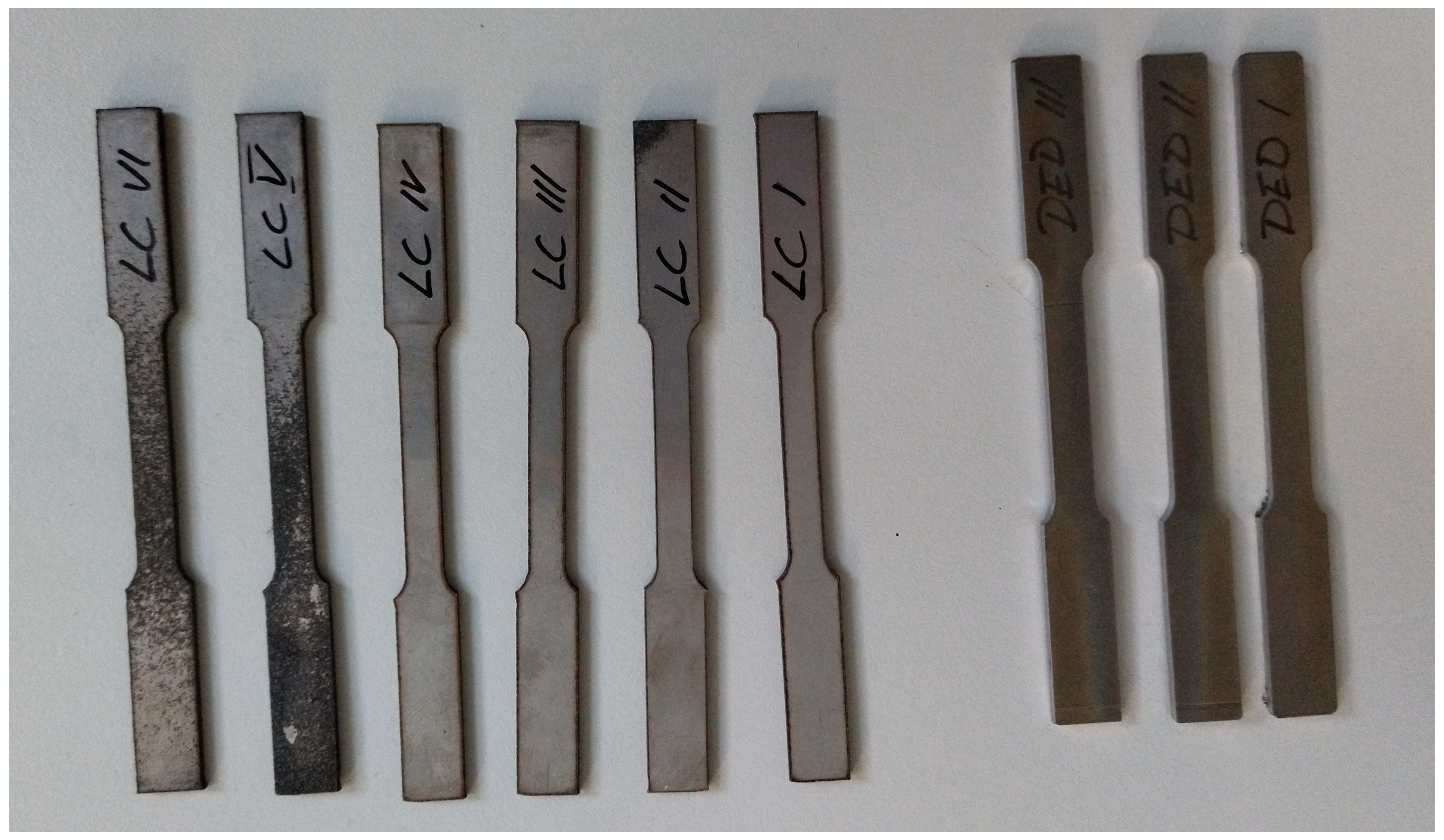
2.1. Specimens Fabrication
To determine the purpose of the research, two sets of specimens were made according to the ASTM standard E8-E8M-2016a [16]. The geometric shape of the specimens made is of plate-type, having the dimensions represented in the technical drawing from Figure 2.
Figure 2.
Specimen dimensions with respect to ASTM standard.
The materials used to manufacture the four sets of specimens were equivalent in terms of composition. In the case of the first specimen set, representing parts made by subtractive processes, the specimens were made of laminated sheet, while for the sets of specimens fabricated with hybrid manufacturing technology (DED and CNC milling), the material was X2CrNiMo17-13-2 as metal powder from Sandvik Osprey® powders.
For the specimens fabricated with subtractive processes, a set of 5 specimens was made and an extra one was made for machine calibration and fixture validation. The specimens were cut from a single stainless steel sheet with 2 mm thickness using a 1800 W laser.
In the case of the specimens manufactured with hybrid technology, the additive manufacturing process consisted of a DED process using X2CrNiMo17-13-2 metal powder. The equipment used for the hybrid manufacturing process was a DMG Lasertec 65 DED hybrid machine with a COAX 14-coaxial nozzle technology installed at Compa S.A. Sibiu, Romania. The nozzle assembly is depicted in Figure 3.
Figure 3.
COAX 14 nozzle used in the metal powders deposition.
The flow of metal powder is distributed through holes placed at the base of the cone and the laser beam exits through the central hole. The DED additive manufacturing parameters are shown in Table 2.
Table 2.
DED manufacturing parameters.
Considering that the laser deposition process creates a rough, uneven surface with low geometrical precision [17], to obtain the right dimensions for the specimens, the 3D DED specimen was fabricated with a 2 mm offset on all the part’s faces surfaces, which was removed using CNC manufacturing to obtain a precise geometry in conformity with the ASTM standard [16,18]. Moreover, to study the influence of the height of the DED process on the mechanical properties of the final part, the specimens were fabricated one on top of the other in stacks of 3, as detailed in Figure 4. Considering that we have 3 specimens with an offset of 0.15 mm between them and the base and an addition of 2 mm on top, the total height of the stack is 8.45 mm.
Figure 4.
Stack of 3 specimens prepared for DED hybrid manufacturing.
For the DED process, a nozzle with a diameter of 3 mm and a 13 mm offset between the printed layer and the nozzle were used. As for the powder carrier gas, argon was chosen. The initial laser power was set to 1800 W to aid the bounding of the first layer to the support plate. Progressively, the laser power was decreased by 100 W at each layer until a deposition power of 1400 W was reached. The layer height was 0.9 mm, and the specimens were printed on an S235JR metal plate with a thickness of 18 mm. To obtain the required geometrical and dimensional precision, the stack of specimens was milled on the upper surface and on the contour. The fabrication process is detailed in Figure 5.
Figure 5.
Specimen fabrication: (a) 3D model of the specimen stack; (b) specimen fabrication using DED; (c) specimen finishing process simulation using CNC milling; (d) specimen stack after finishing.
After the hybrid manufacturing process, the specimens (Figure 6) were removed from the metal plate using an electrical discharge machining process which also sliced the specimen stack to single specimens with a 2 mm thickness. The electrical discharge process used a 0.15 mm wire to separate the specimens.
Figure 6.
Subtractive manufactured (left) and hybrid manufactured (right) specimen sets.
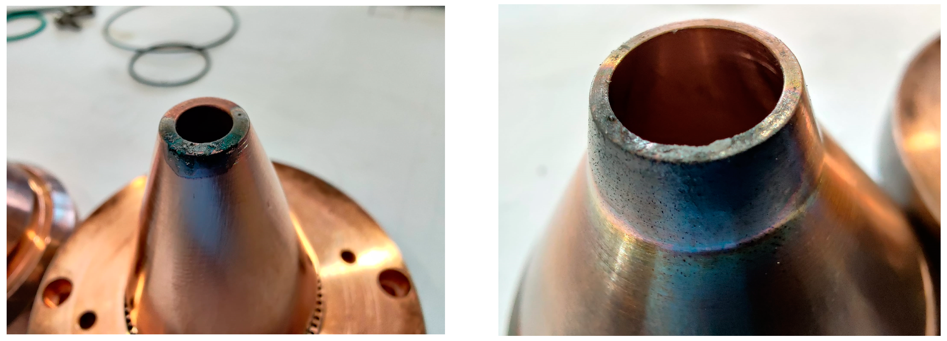
2.2. Encountered Issues
During the specimen’s fabrication using the hybrid technology, several issues were encountered due to positional errors of the base plate in the machine’s vice. Due to the residual material, which is splashed on the base plate’s surface, angular positional inaccuracies are developed if the base plate is not cleaned before reuse [19].
The 3D printing process requires careful control of the laser power to avoid damaging the base plate and the nozzle. If the laser power is too high (e.g., 1800 W for the entire stack of specimens), the base plate can warp due to thermal expansion and cause cracks on the printed parts [20]. Moreover, the nozzle can also suffer from thermal shock and permanent damage if the temperature rises too quickly [21]. Moreover, if the distance from the base material is not optimal, residual material splashes can affect the nozzle as depicted in Figure 7. Therefore, it is important to use a face milling finishing operation to clean the base plate and to adjust the laser power according to the material and thickness of the specimens.
Figure 7.
Nozzle damage due to excessive laser power and residual material splashes.
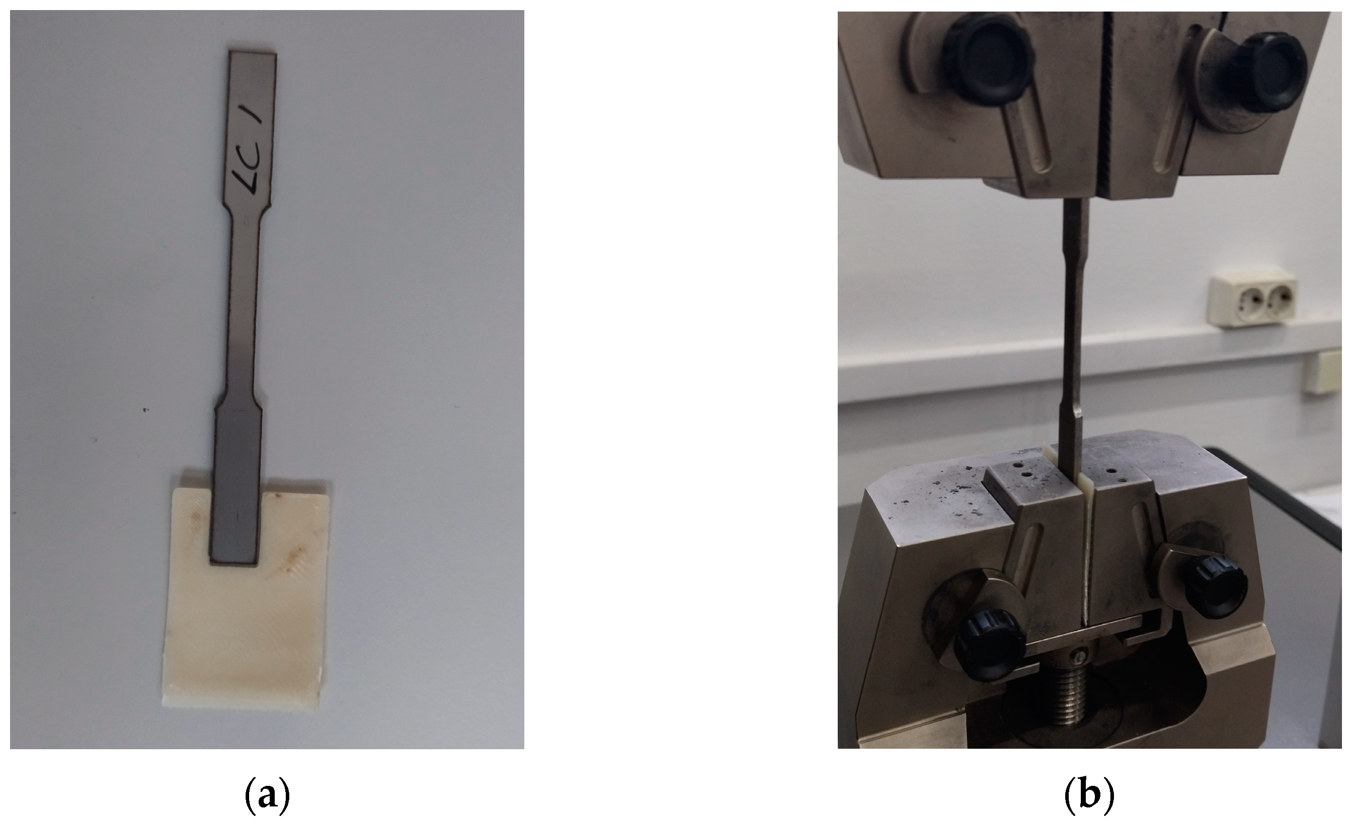
2.3. Experimental Procedure
The specimens were subjected to tension tests until failure according to the ASTM E8/E8M standard [15] using a Galdabini Quasar 25 material testing machine to determine their mechanical properties. A 3D-printed mould was used to ensure a consistent placement of the specimens in the machine’s grips, as shown in Figure 8, and to position the axis of the test specimen coincidently with the centre line of the heads of the testing machine in order to minimise bending stresses which could affect the results. The 3D-printed mould did not affect the experimental results as it is thinner and weaker than the specimens and made of plastic material. The crosshead speed used for the tests was set to 0.5 mm/min.
Figure 8.
Orientation device (a) and attachment of a specimen to the testing machine (b).
3. Results
The experiment involved testing five conventional specimens and five hybrid stacks, each consisting of three specimens produced by DED processes. The DED specimens are further referred to with the following codes: DED Level 1 (DED L1), the specimen from the top level of the stack; DED Level 2 (DED L2), the specimen from the middle level of the stack; and DED Level 3 (DED L3), the specimen from the bottom level of the stack which is deposited on the S235JR base plate. All specimens were subjected to tensile loading until they failed. The purpose of this experiment is to demonstrate that the parts made by DED methods have superior mechanical properties compared to the stainless steel used for making forging tools and moulds.
The tensile tests conducted on specimens produced by subtractive processes (laser-cut stainless steel) and hybrid manufacturing (DED process) revealed notable differences in mechanical properties, as can be seen in the boxplot for each specimen from Figure 9.

Figure 9.
Boxplot of the stress values resulting from the tensile loading for each specimen.
The maximum tensile strengths obtained from the tests exhibit distinct patterns between the different specimen groups, as detailed in Table 3.
Table 3.
Specimens’ mechanical parameters.
Since the test values of each specimen set are consistent (Figure 9) with their counterparts, no outliers were identified among the specimens. Therefore, to highlight the differences between the types of specimens, the mean value for each set of specimens was calculated and compared.
The scatter plot (Figure 10) showcases a comparative view of stress in [MPa] against the percentage of elongation for each specimen group’s mean value. Elongation (%) or reduction in area (%) represents the tensile ductility. The equation of determining elongation (%) was calculated by the testing machine using Equation (1), where L0 is the initial length of the sample and ΔL is the difference between the initial length and the elongated final length.
Figure 10.
Stress–strain curve for the mean values of each specimen set.
This graphical representation provides valuable insights into the material behaviour under tension for both subtractive and hybrid manufacturing methods.
Subtractive (laser-cut stainless steel) specimens exhibit a higher elongation at lower stress levels, suggesting a more ductile behaviour in response to tension. In contrast, specimens produced through the DED process exhibit a notably different pattern on the scatter plot. They portray a higher stress and lower elongation tendency, particularly influenced by the layer level of the DED deposition. The specimens produced through the DED process demonstrate a behaviour linked to the layer level of deposition. The highest level (DED L1) exhibits the lowest tensile strength, indicating decreased strength, but the highest elongation percentage, indicative of a more ductile behaviour. The initial DED level (DED L3) displays the highest tensile strength but also a more brittle nature. The middle specimens (DED L2) exhibit a moderate tensile strength compared to the initial and final specimens but show a reduced elongation. This behaviour leans towards brittleness, likely attributed to the middle layers retaining heat for an extended duration during the deposition process. Heat dissipation dynamics differ for these layers, with the base level dissipating heat into the metal base plate and the final level dissipating heat into the atmosphere.
Using Minitab 20 software, a regression analysis (Figure 11) conducted for each specimen group’s stress and % elongation scatter plot enabled the creation of prediction plots, offering an empirical representation of the material behaviours under tension. The prediction plots contain the stress–strain curve for the mean of each specimen group, visually presenting the relationship between stress and % elongation.
Figure 11.
Prediction plot for mean values of stress and % strain based on experimental results for each specimen set.
The red line within each prediction plot represents the predicted X and Y values, offering a trend line that highlights the anticipated material behaviour based on the regression analysis. An essential aspect of these plots is the inclusion of a 95% prediction interval. This interval denotes a range within which 95% of the observed data points are expected to fall, illustrating the uncertainty associated with the predictions. These prediction plots hold significant implications for material engineers and manufacturers in selecting suitable materials and manufacturing methods for specific applications. The curves highlight the expected behaviours and the associated uncertainty, aiding in informed decision-making.
Observations from the tests indicate a clear resilience in specimens produced through the DED hybrid process compared to those obtained via conventional methods. Especially, specimens closer to the deposition base exhibit increased strength, a factor significantly influenced by material specifications. Specifically, the initial laser power set at 1800 W gradually decreased by 100 W per layer until reaching 1400 W, contributing to this observed trend [21,22,23,24].
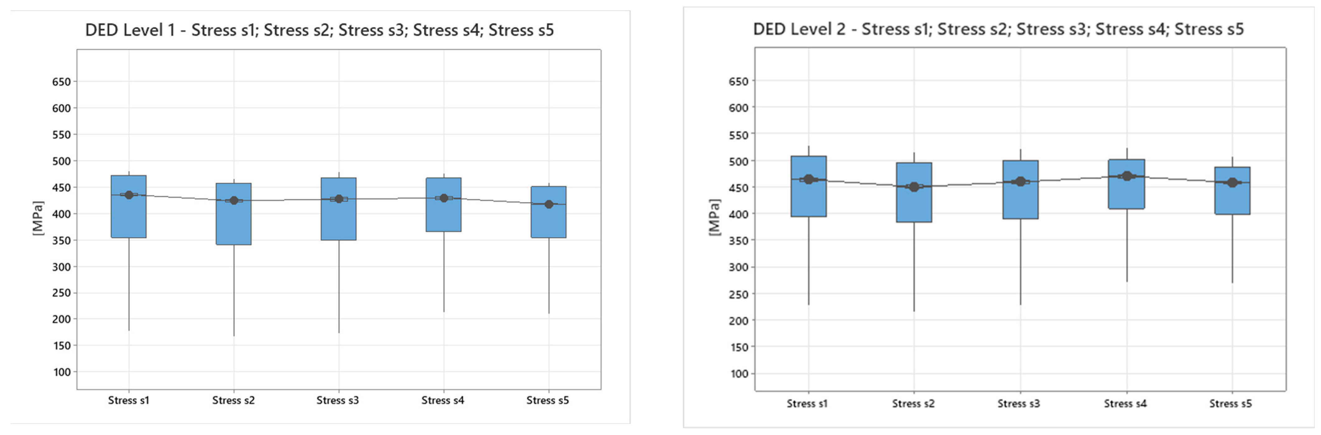
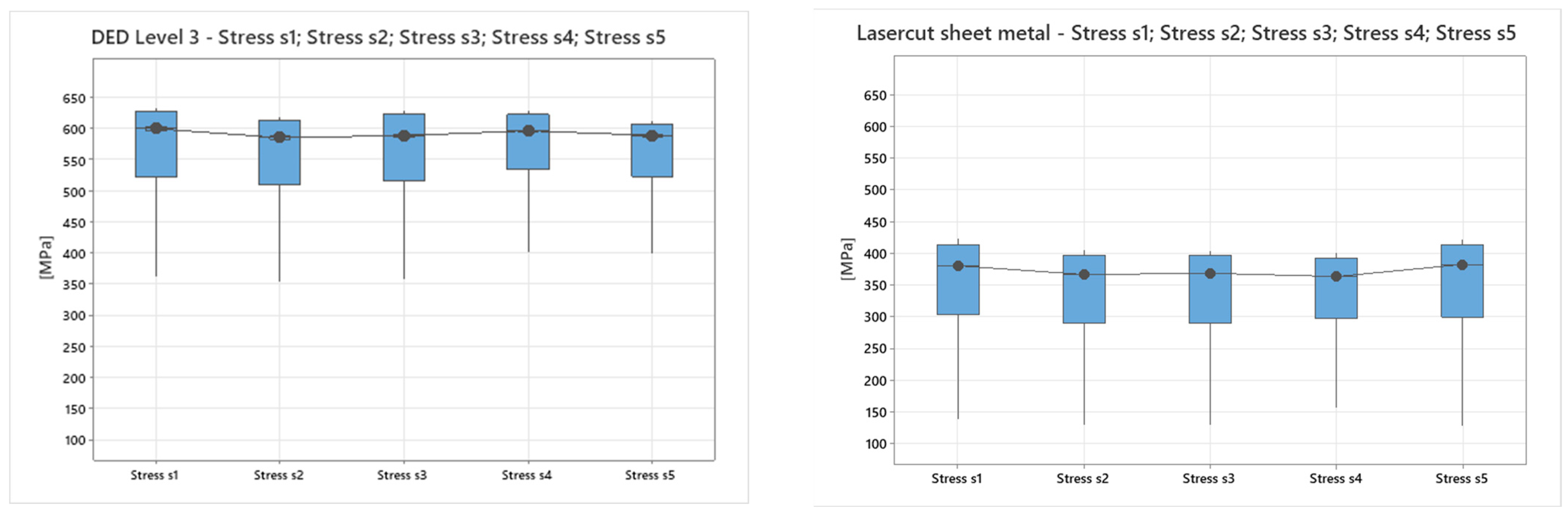
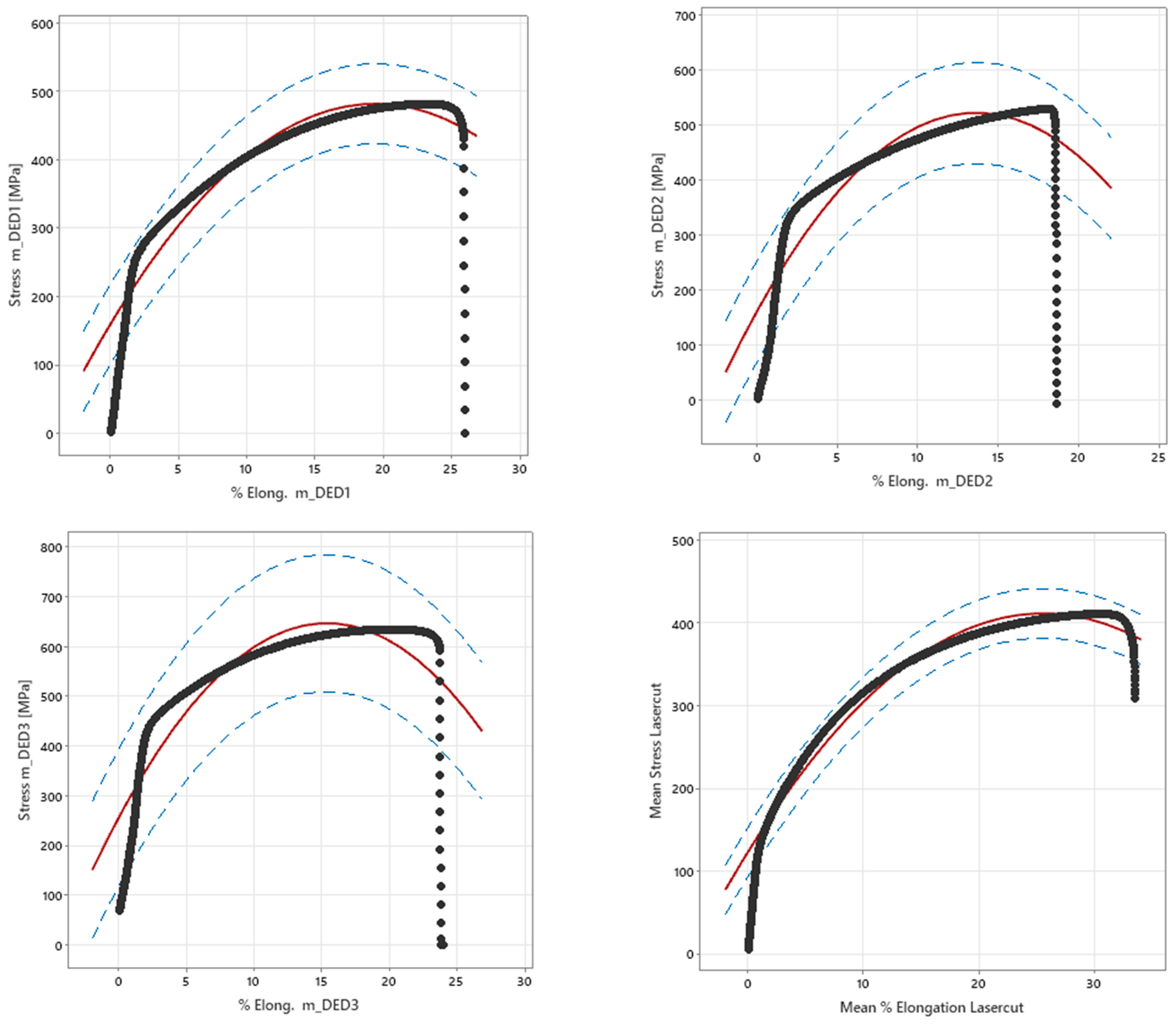
Tensile Strength vs. Ductility in DED Components
The layering strategy in DED plays an essential role in determining mechanical properties. Lower layers closer to the substrate (base material) may experience enhanced tensile strength due to rapid cooling, grain refinement, and dislocation density increase. However, this rapid cooling might compromise ductility by inducing micro-fissures or a non-uniform microstructure [25]. Extending our analysis to additional case studies, we consider the example of DED-produced turbine blades [26,27]. For this type of component, the outer layers, subjected to higher stress, demand increased strength to withstand forces during operation. Therefore, these outer layers could be designed with a focus on higher tensile strength, achieved by optimising cooling rates, controlling deposition parameters, and sacrificing some ductility. Similarly, inner layers could prioritise ductility to withstand dynamic loading conditions. Control parameters like laser power, deposition speed, and layer thickness significantly impact this balance. A higher laser power might enhance strength but at the expense of ductility due to rapid solidification, while slower cooling rates could improve ductility but might reduce overall strength.
The selection of alloy compositions in DED also influences this balance. For instance, nickel-based superalloys might prioritise strength over ductility due to their high-temperature applications, whereas certain steel alloys might aim for a balance between the two properties.
This expanded discussion demonstrates the compromises and strategic considerations involved in balancing tensile strength and ductility in DED-produced components across various industries and applications.
4. Metal Forging Tools and Moulds Recondition Case Studies
Repair processes for metal forging tools and moulds using DED involve the application of additive manufacturing techniques to restore, modify, or enhance these critical components used in metal forging processes [28].
The first step involves a thorough assessment of the damaged or worn-out forging tools or moulds. This includes identifying areas of erosion, cracks, wear, or any other structural issues. Utilising digital models and Siemens NX 12 CAD software, the repair strategy is designed. This involves planning the deposition paths and identifying the areas needing repair or modification. Selecting suitable materials compatible with the original component and capable of withstanding the high temperatures and stresses involved in forging operations is a critical phase of the repair process.
The DED process involves precisely depositing material layer by layer onto the damaged areas of the tool or mould. This could involve the addition of compatible metals or specialised alloys to restore lost material or reinforce weak sections. After the deposition process, finishing steps like milling or machining are required to achieve the desired surface quality, accuracy, and tolerances.
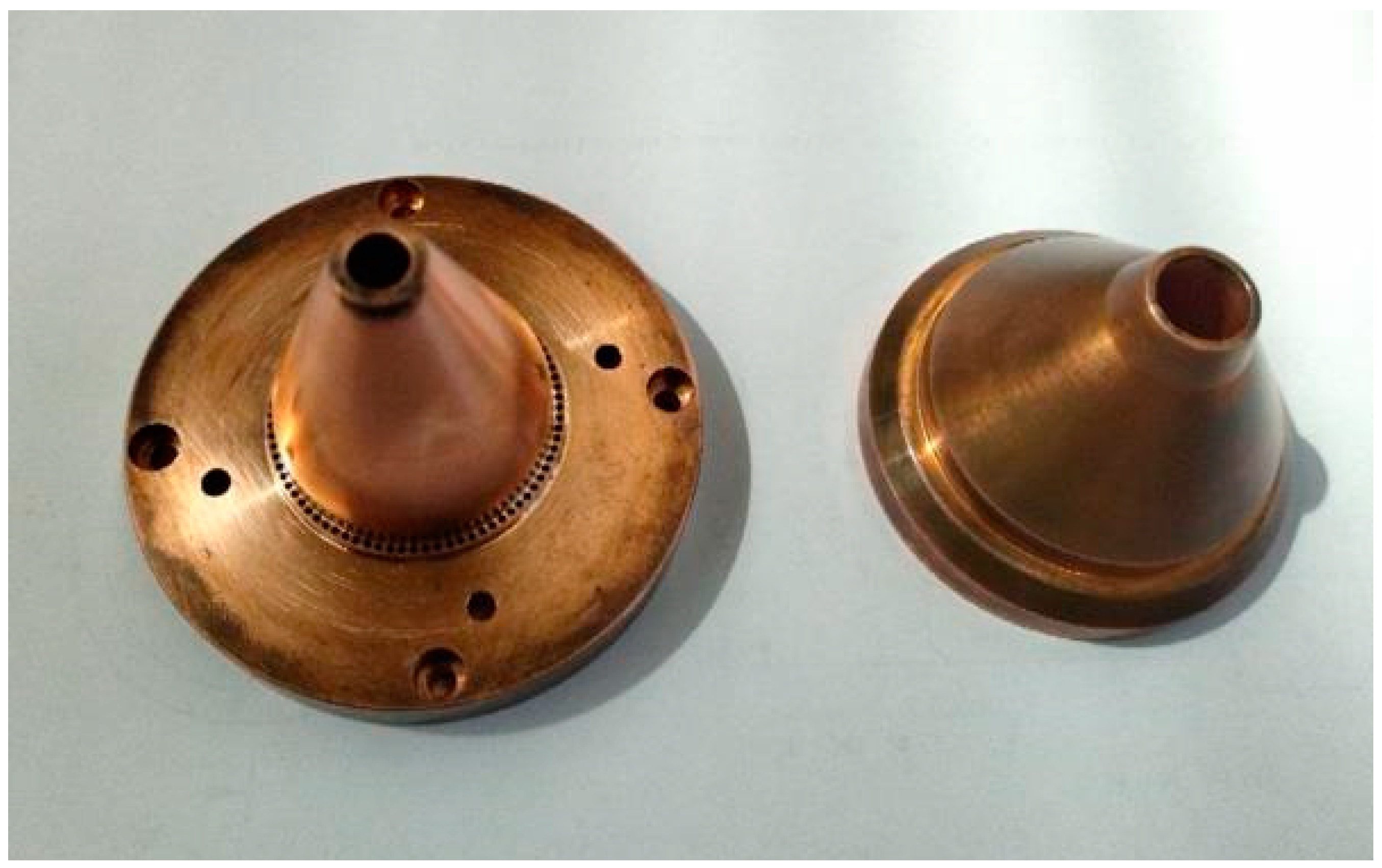
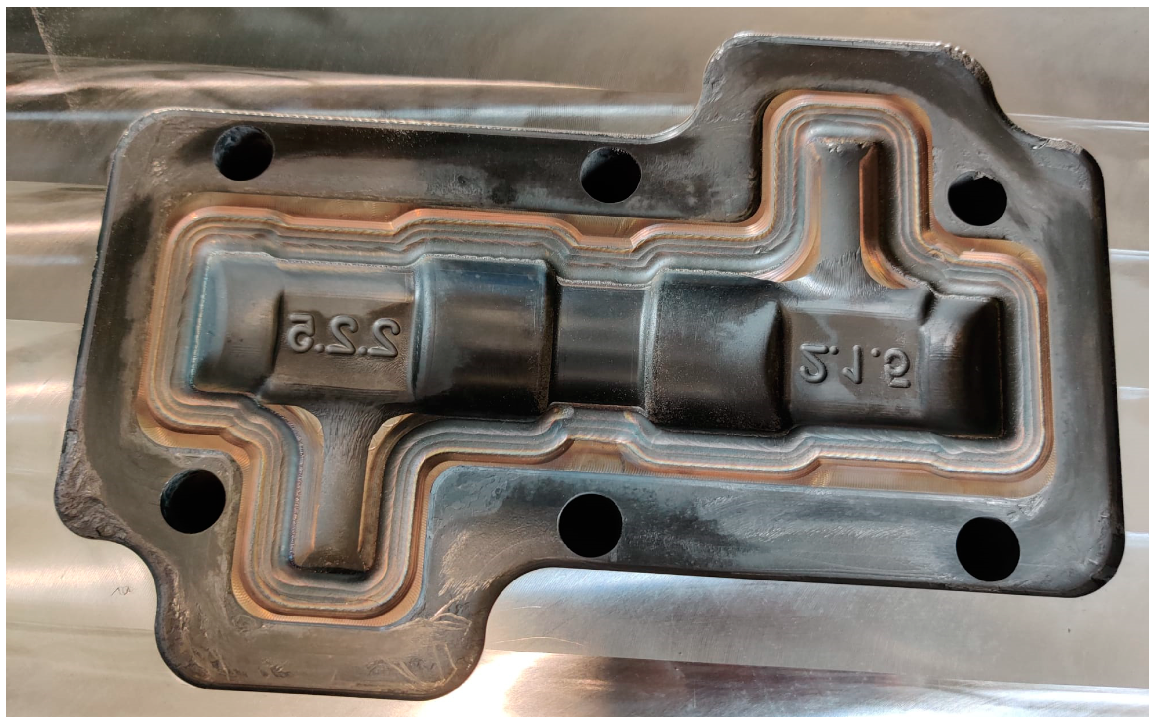
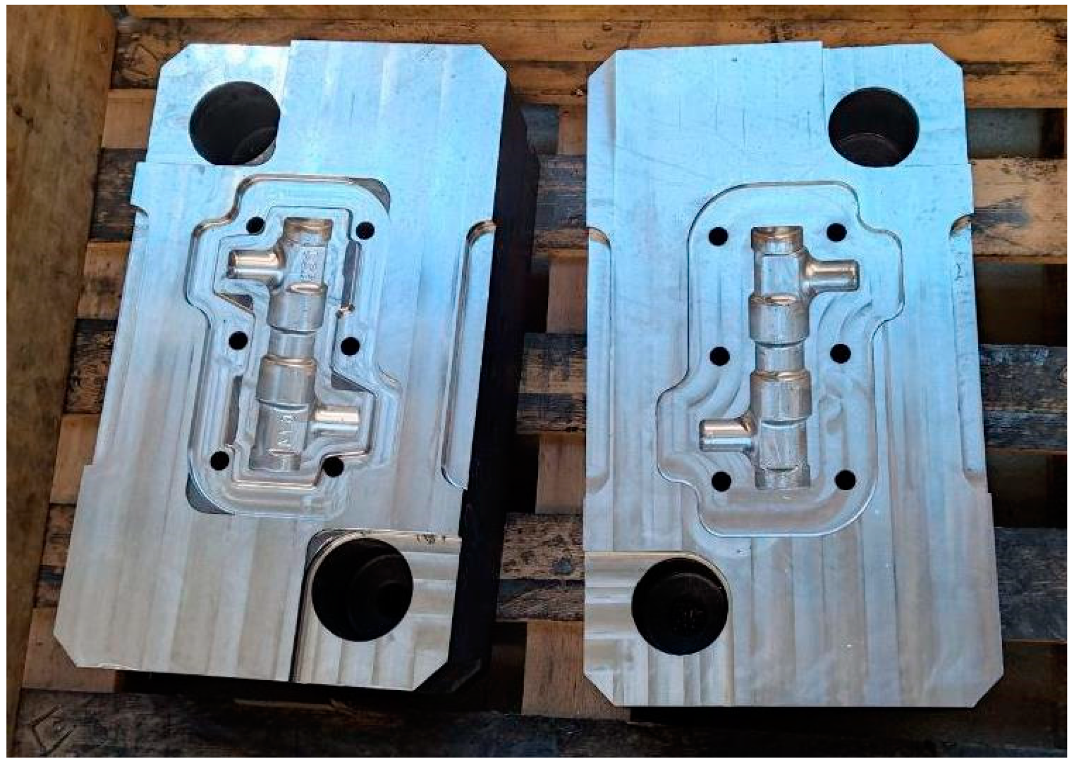
4.1. Case Study 1—Forging Mould Repair
The mould consisted of two semi-moulds which are used in hot forging processes to manufacture the rough stock for future products.
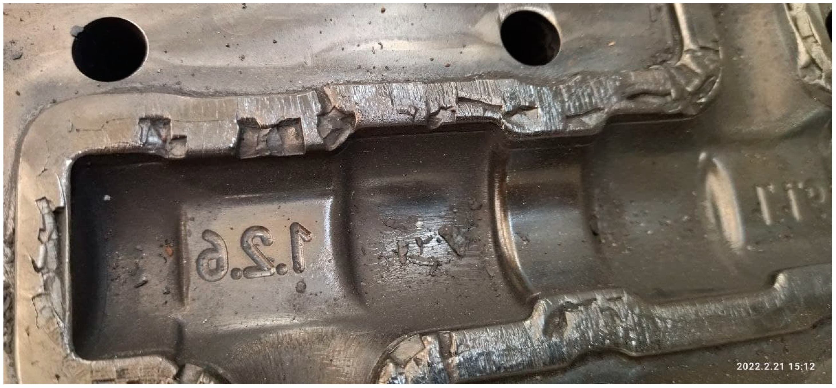
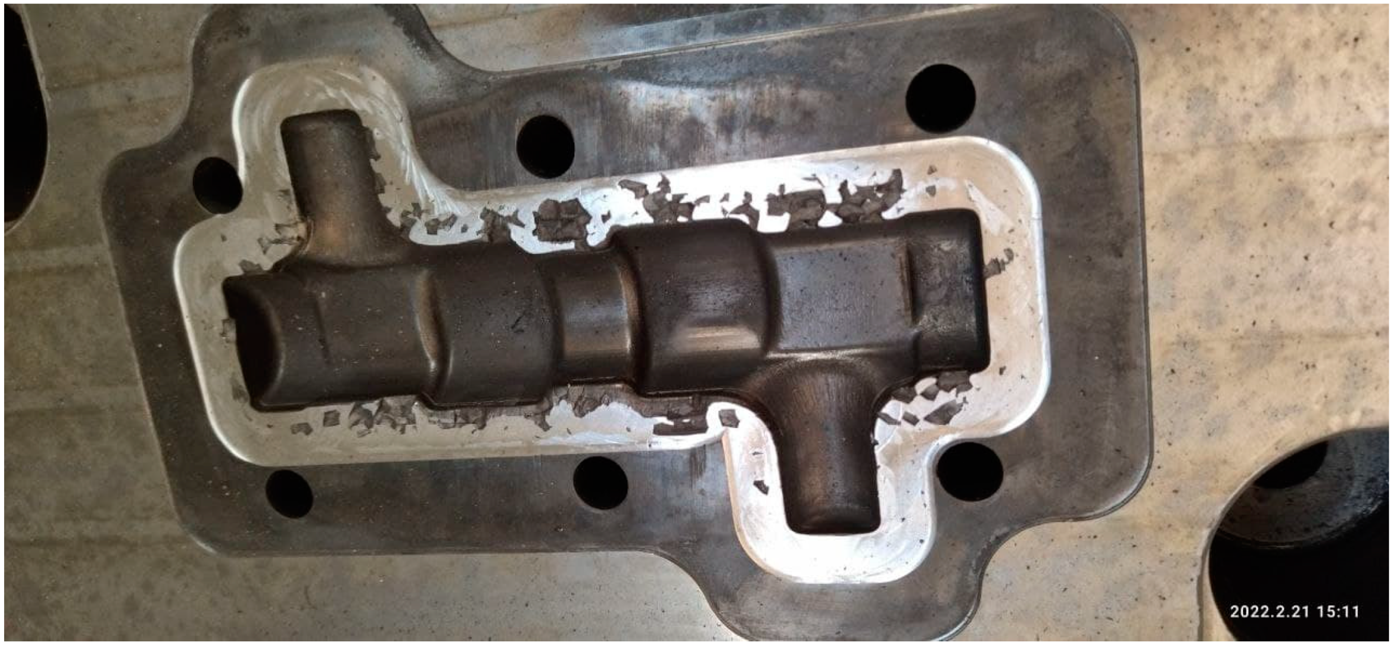
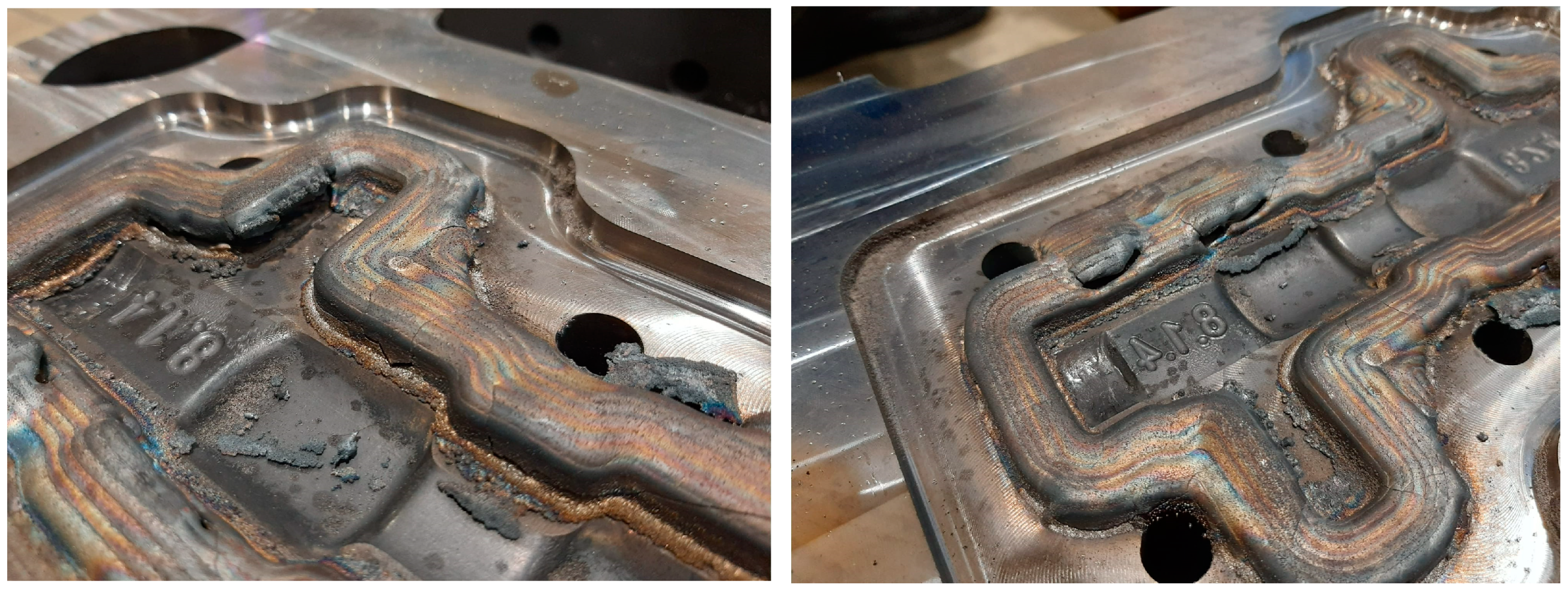
4.1.1. Problem Description
Following the hot forging process, the semi-moulds encounter wear and tear, especially along the rounded edges defining the cavity of the resulting product (e.g., rough stock). Additionally, material removal during the forging process causes pitting, damaging the active surface of the mould cavity and rendering it unusable, as detailed in Figure 12.
Figure 12.
Affected areas of the mould after the forging cycle.
4.1.2. Analysis of Mould Repair Processes (Conventional vs. Hybrid)
Mould repairs are classified based on the extent of damage: routine maintenance is conducted within the mould’s wear limits and comprehensive repairs address significant damage. Comprehensive repairs typically involve two approaches: conventional methods utilising manual welding and mechanical machining or hybrid processes combining metal powder deposition with subsequent mechanical machining.
Conventional repair techniques involve an initial measurement of the damaged area, followed by manual filling using welding material and CNC-based re-machining. However, for this scenario, the mould’s extensive damage necessitated a hybrid repair approach, ensuring improved reliability for high-stress mass production. This hybrid method fuses directed energy deposition (DED) with CNC machining. Beginning with a precise measurement of the damaged area, the process involves depositing metal powder onto the affected region and utilising CNC technology to restore the mould to its original dimensions and shape.
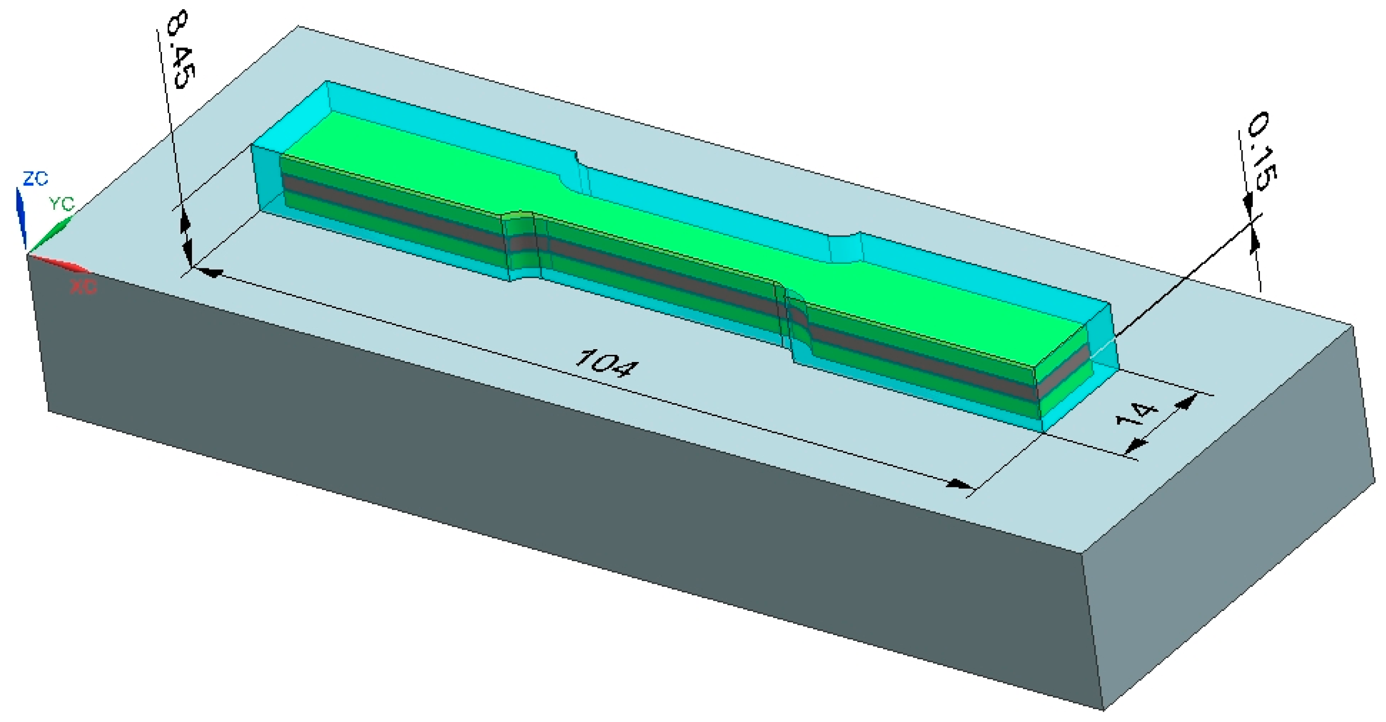
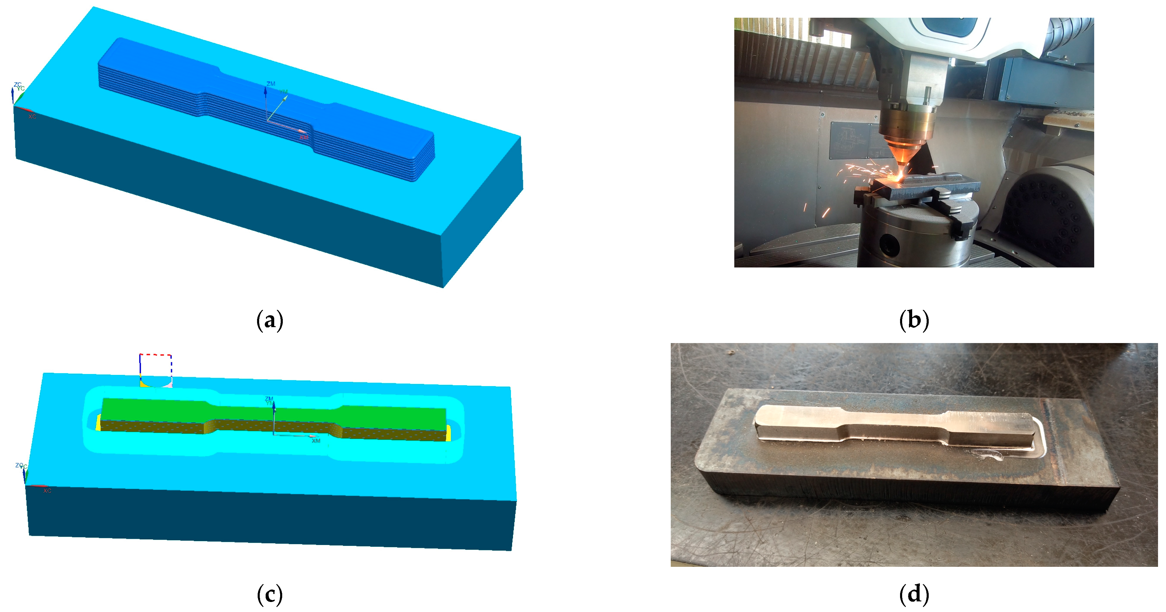
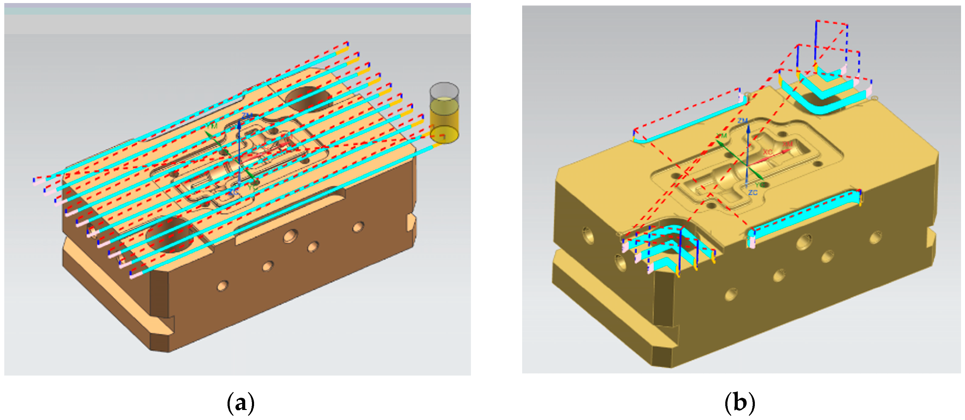
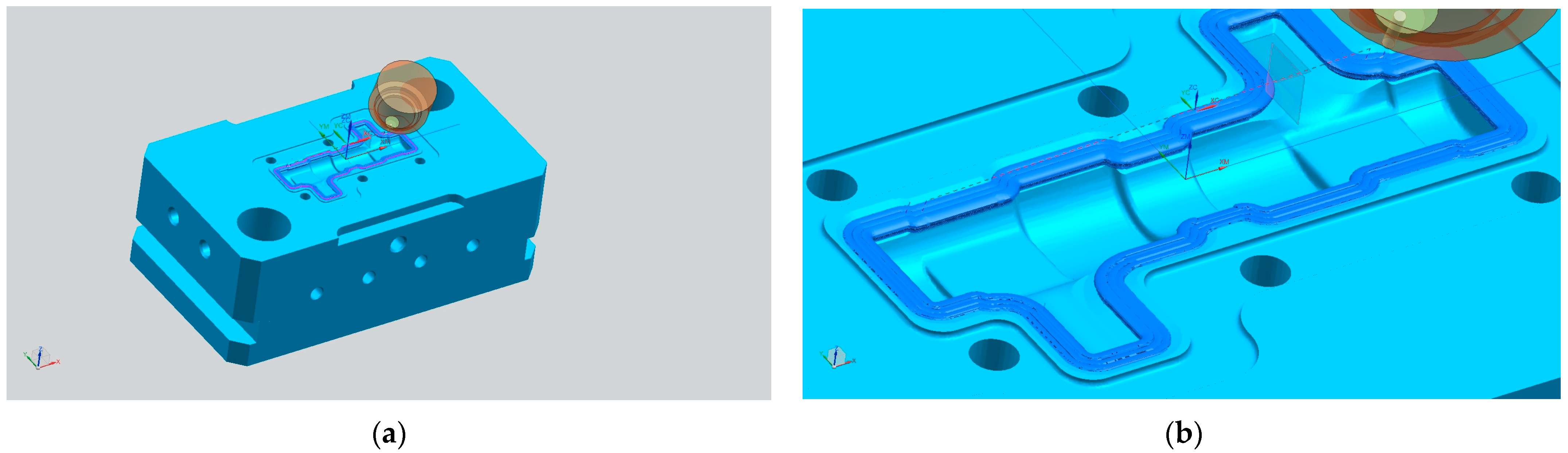
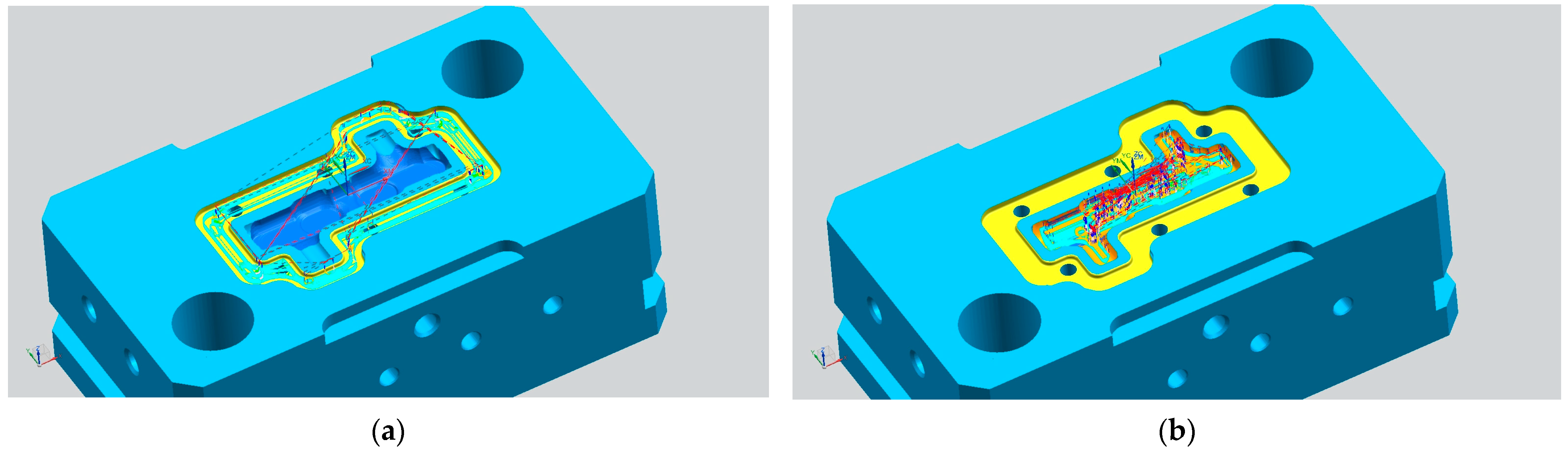
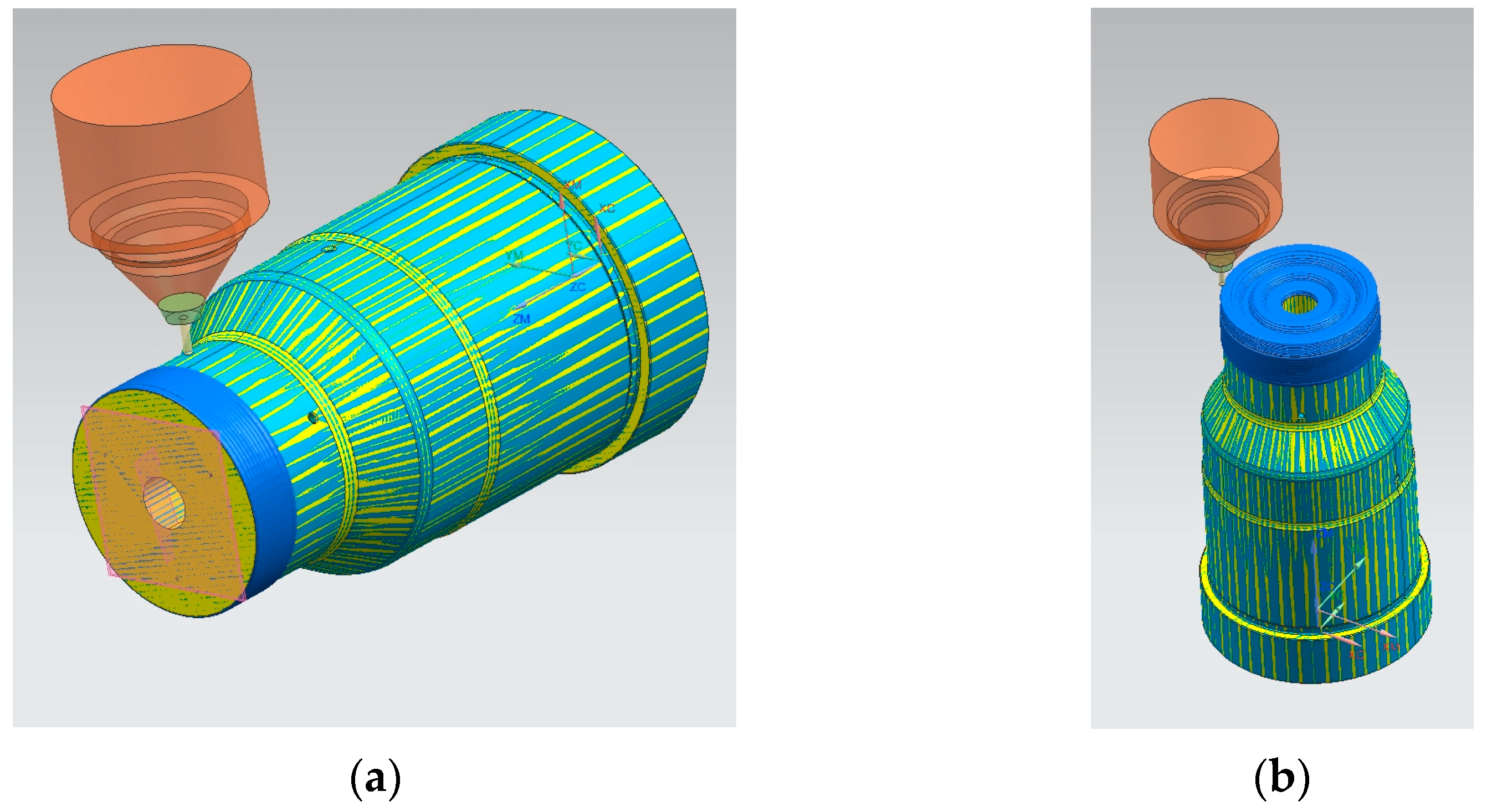
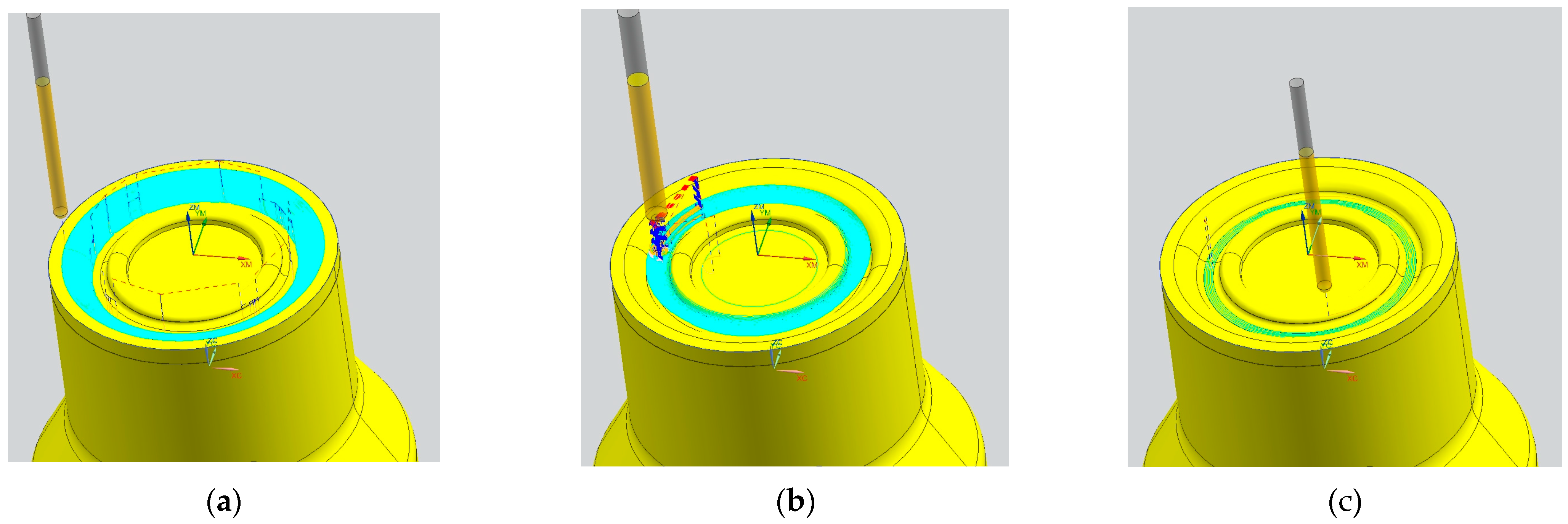
4.1.3. Design and Simulation of the Repair Process
In the NX software, designing the Computer-Aided Manufacturing (CAM) process for repairing the forging mould involved the initial removal of the damaged area (Figure 13), necessitating measurements to determine the depth of wear and pitting on the active surface of the mould cavity and its rounded edges. Subsequently, a CAD model was created, guiding the repair strategy based on an original CAD model of the mould and the required material for the DED process.
Figure 13.
Affected mould after the initial removal of the damaged area.
The CAM process started with a face milling operation aimed at restoring the top surface of the mould by eliminating imperfections. Following this, specific areas of the mould were milled as per the CAD data, ensuring precision and adherence of the repair design (Figure 14).
Figure 14.
Affected initial simulation process: face milling (a) and guidance milling (b).
Continuing the process, the mould was prepared for DED deposition. An angled surface for deposition was chosen to enhance the strength of the rounded edges, necessitating a contour milling operation. Additionally, the active surfaces within the mould cavity underwent rough milling to ensure precise parts production (Figure 15).
Figure 15.
CNC machining before DED process: cavity milling (a) and border milling (b).
Upon completion of the preparation milling operations, the DED process simulation was initiated, depositing layers onto the previously angled surfaces in accordance with the original mould 3D model (Figure 16).
Figure 16.
DED process: CAM simulation (a) and printed layers (b).
Post-deposition, rough milling, semi-finishing, and finishing milling operations were performed on both the cavity surfaces and the previously deposited material layers (Figure 17). These operations continued until the mould cavity reached the prescribed tolerances, ensuring the final mould matched the original 3D model and the required specifications.
Figure 17.
CNC finishing process: cavity rough and rounded edges milling, (a) cavity finishing (b).
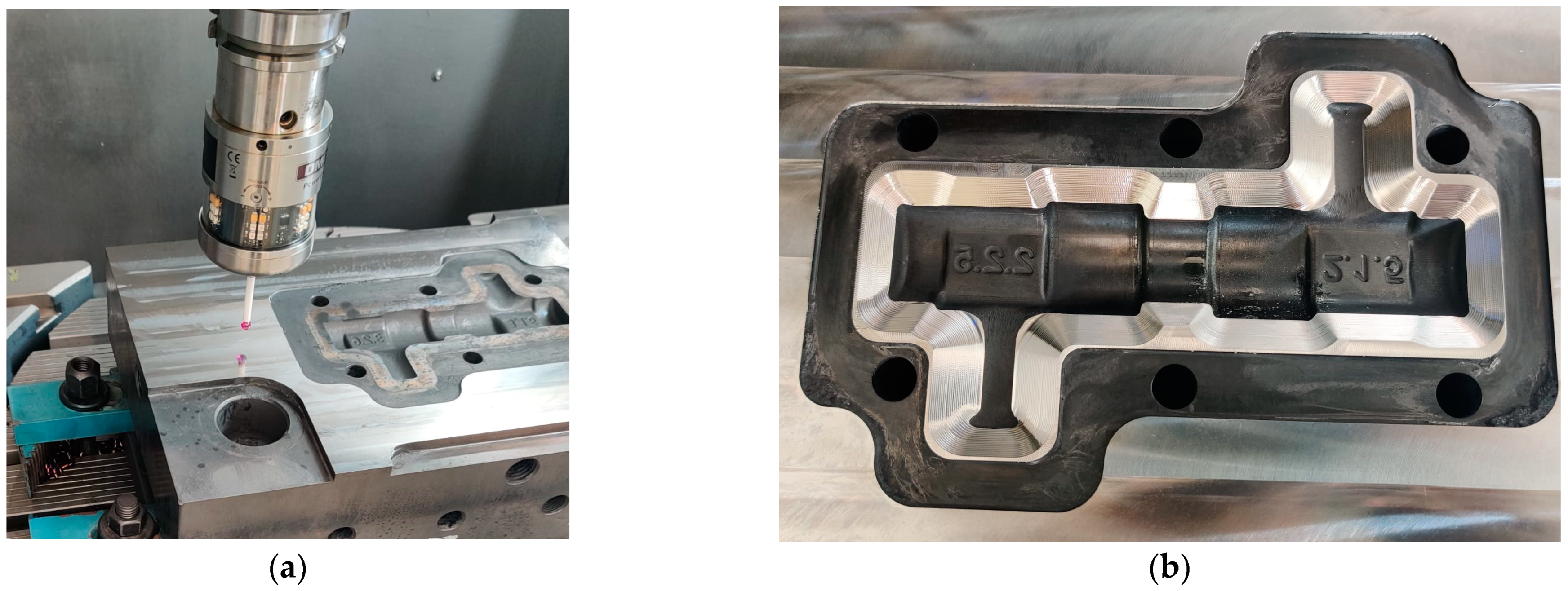
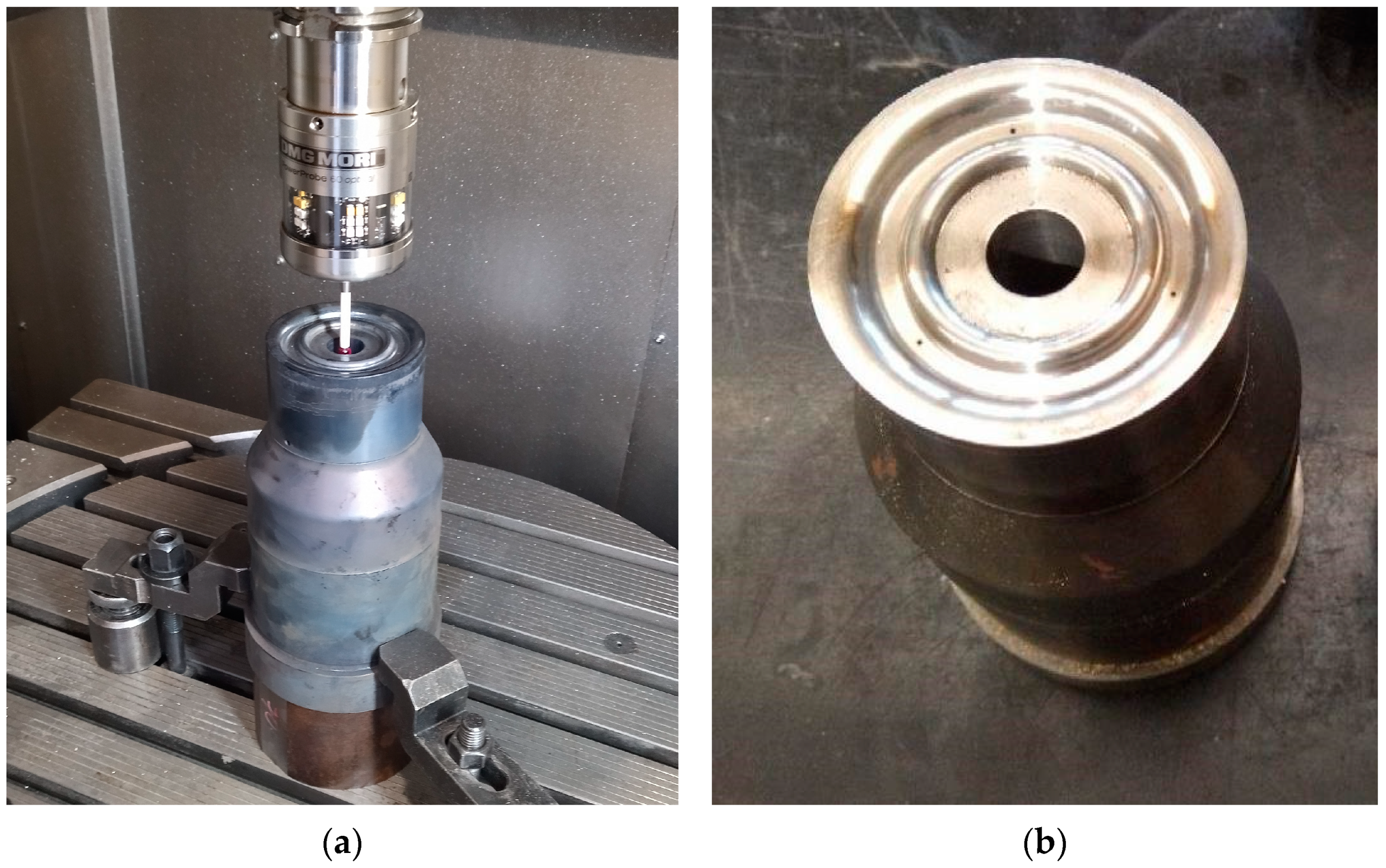
4.1.4. Execution of the Repair Process
Within the hybrid technology, the mould underwent fixation and precise orientation within the CNC machine work offset. Utilising the precision “Renishaw” 3D probe, the mould was meticulously measured. This tool facilitates the palpation of critical areas within the mould, establishing the part’s origin or work offset (Figure 18a).
Figure 18.
(a) Establishing the new machining origin after front milling; (b) cavity roughing milling.
Once the workpiece’s origin was determined, a precise machining, in conformity with the CAM simulation, was performed on the affected mould areas, involving milling processes to rectify cavity irregularities caused by wear (Figure 18b). This step is essential, particularly in creating a smooth, straight surface and an inclined edge corresponding to the active edge of the mould. This preparation phase is crucial for the subsequent DED process to create a new active round edge. The DED process parameters align closely with the technical documentation provided by the material manufacturer. This comprehensive documentation contains essential details such as chemical composition, particle size, powder handling guidelines, metallographic structure, and parameters vital in obtaining optimal material strength and hardness as depicted in Figure 19.
Figure 19.
Mould result after the DED process.
During the DED process, various deposition parameters, including nozzle type, focus size, nozzle distance, laser specifications, carrier gas, power adjustments per layer, layer dimensions, and tracking speed, were meticulously adjusted according to the technical guidelines.
After the completion of roughing, semi-finishing, and final CNC machining operations on the mould cavity (Figure 20), the precision of the active surface area was measured using a Coordinate Measuring Machine (CMM). This meticulous measurement ensures the forging mould meets the prescribed standards, rendering it ready for the hot forging operations.
Figure 20.
Moulds after the repair process—final product.
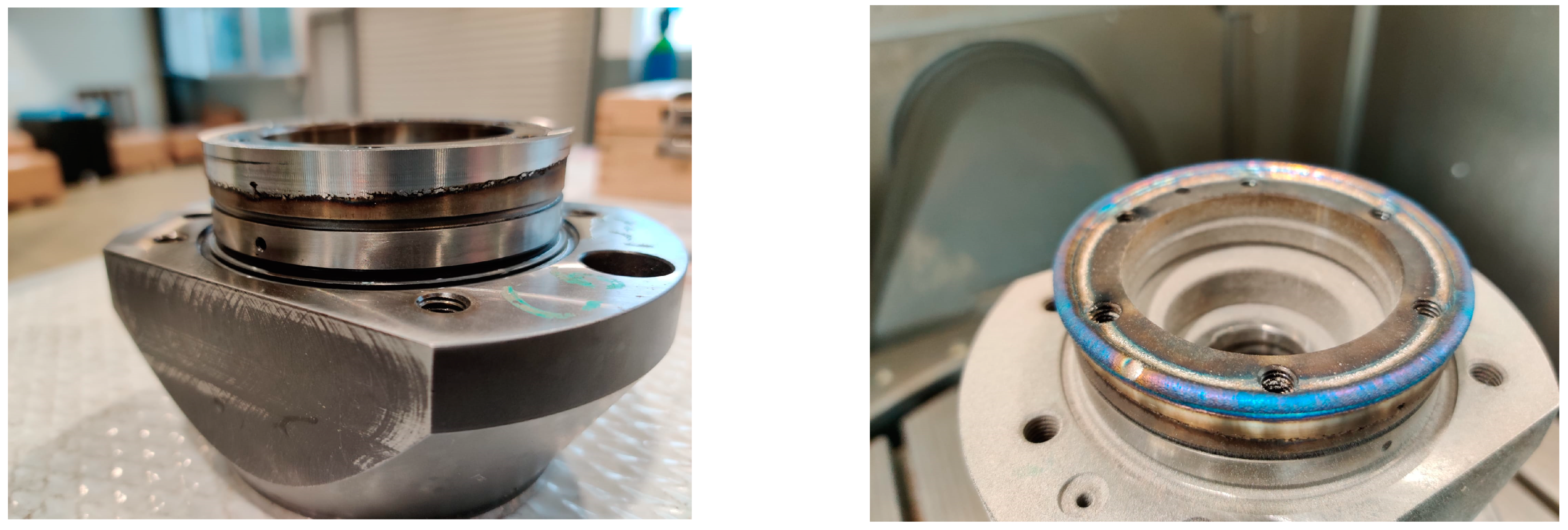
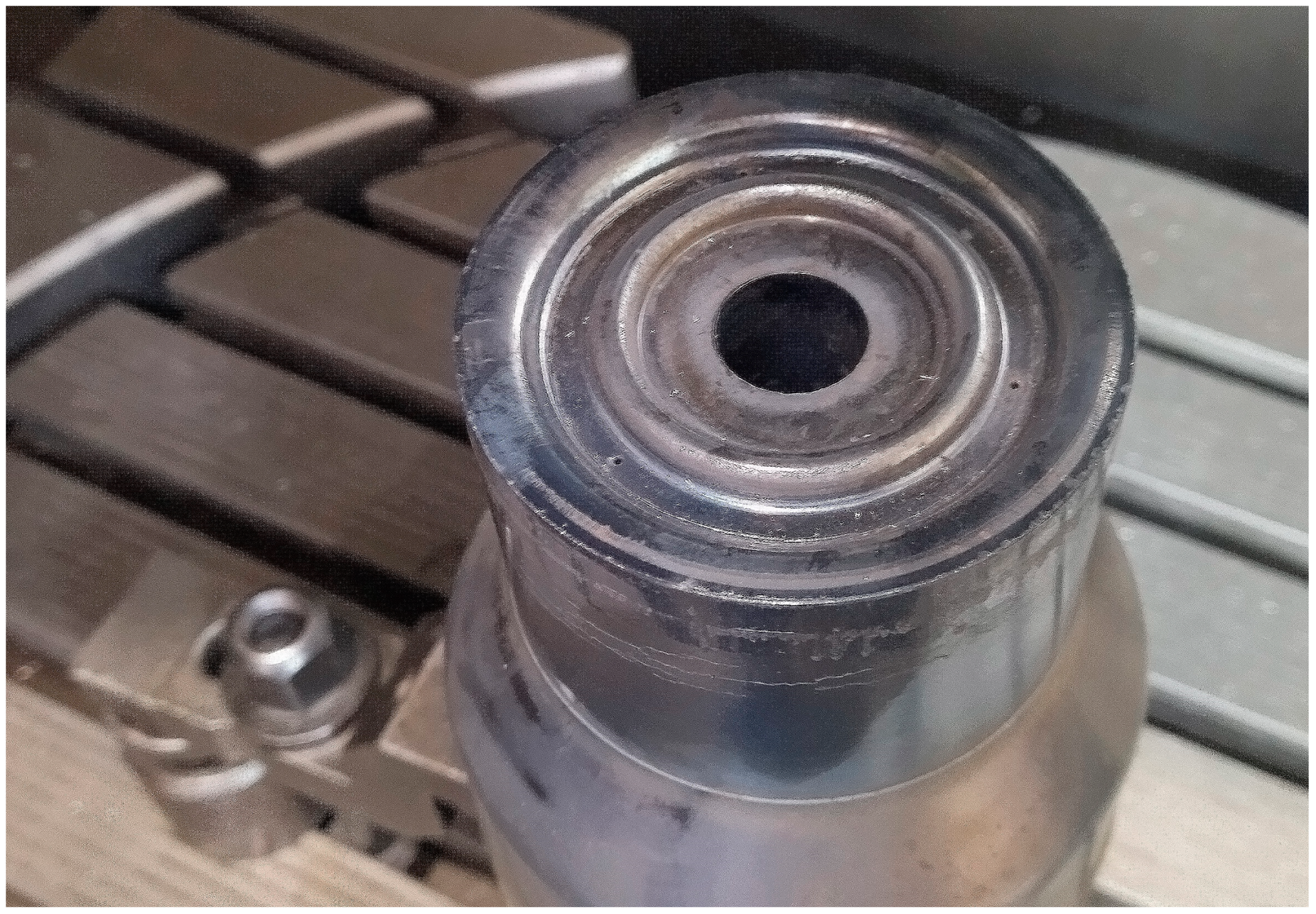
4.2. Case Study 2—Forging Tool Reconstruction and Optimisation
A forging tool is a device that shapes hot material by applying pressure and transferring the imprint of its active surface to a workpiece under controlled conditions. A forging tool assembly consists of a forging tool and a forging mould that fit together to form the desired shape of the material.
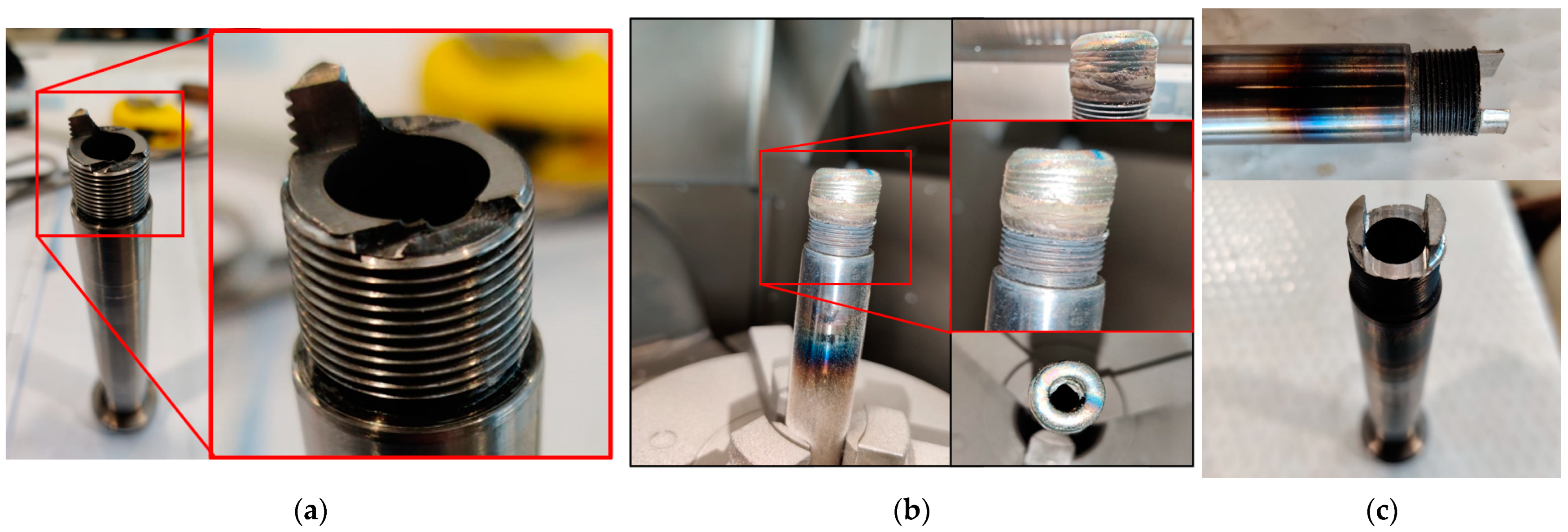
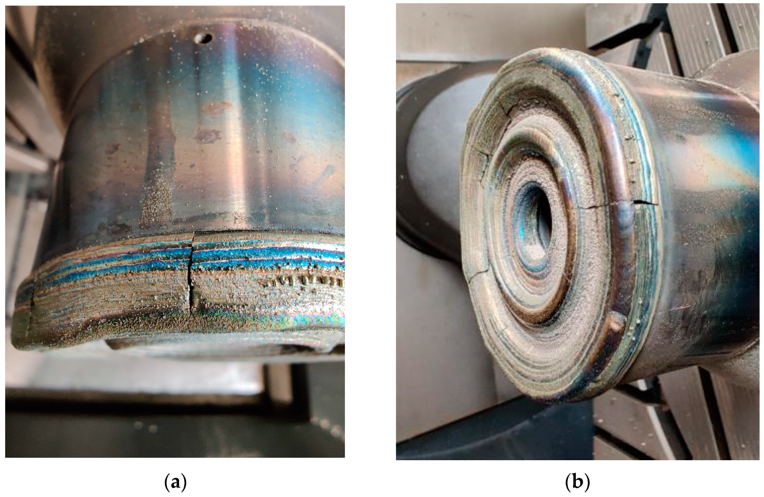
4.2.1. Problem Description
After approximately 9000 parts were produced through forging processes, cracks and wear became evident on the active surface of the forging tool (Figure 21), impacting the precision of the finished products.
Figure 21.
Wear on active surface of the forging tool.
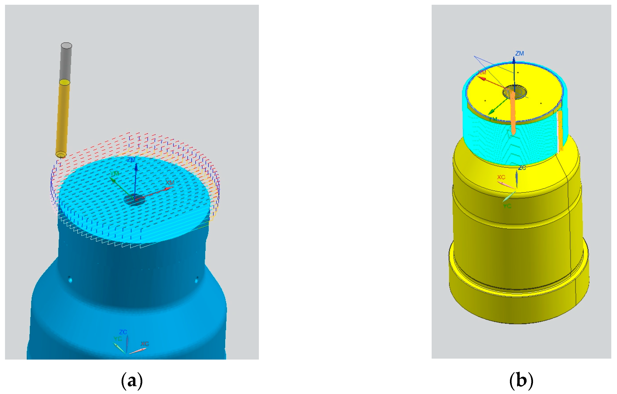
4.2.2. Design and Simulation of the Repair Process
Repairing the active surface of the forging tool often involves face milling or, in some instances, frontal or contour turning methods to remove the worn surface. Hybrid machines with integrated lasers on lathes often employ these turning processes. Circular milling around the base of the active surface can also be used in the case of hybrid milling machines.
In this case, the forging tool repair process was designed in a CAM simulation, which fixes the tool directly onto the Lasertec 65 hybrid machine. The initial profile milling toolpaths were simulated with the aim of creating an optimal base surface for the DED process (Figure 22).
Figure 22.
Preparation process for DED deposition: face milling (a) and circular milling (b).
Initially, the DED process simulation focused on depositing material on the cylindrical area of the forging tool. Subsequently, new material was added to build layers on the frontal area, reconstructing the active surface (Figure 23).
Figure 23.
DED simulation process: radial deposition (a) and active surface deposition (b).
After the DED material deposition process, the active surface of the tool underwent rough, semi-finished, and finishing milling phases, ensuring restoration and optimal finishing (Figure 24).
Figure 24.
CNC finishing process: roughing, (a) semi-finishing, (b) finishing (c).
4.2.3. Execution of the Repair Process
The initial step involved securing the forging tool onto the machine table, followed by precise measurements using the “Renishaw” 3D probe to determine its position and axis (Figure 25a). The CNC program work offset was aligned with the bottom of the forging tool.
Figure 25.
(a) Work offset coordinate system measurement; (b) forging tool after the reprofiling process (finished product).
During the next stage, a front milling operation was conducted to establish the deposition base. The depth of this milling may vary based on the extent of wear and damage observed on the active profile of the forging tool. After the creation of the deposition base, a measurement and verification process ensured precision in the DED process. The succeeding laser deposition process was executed, and once the material was cooled to ambient temperature, mechanical operations involving roughing, semi-finishing, and finishing were applied. These operations are mandatory in achieving the desired final profile of the repaired forging tool (Figure 25b).
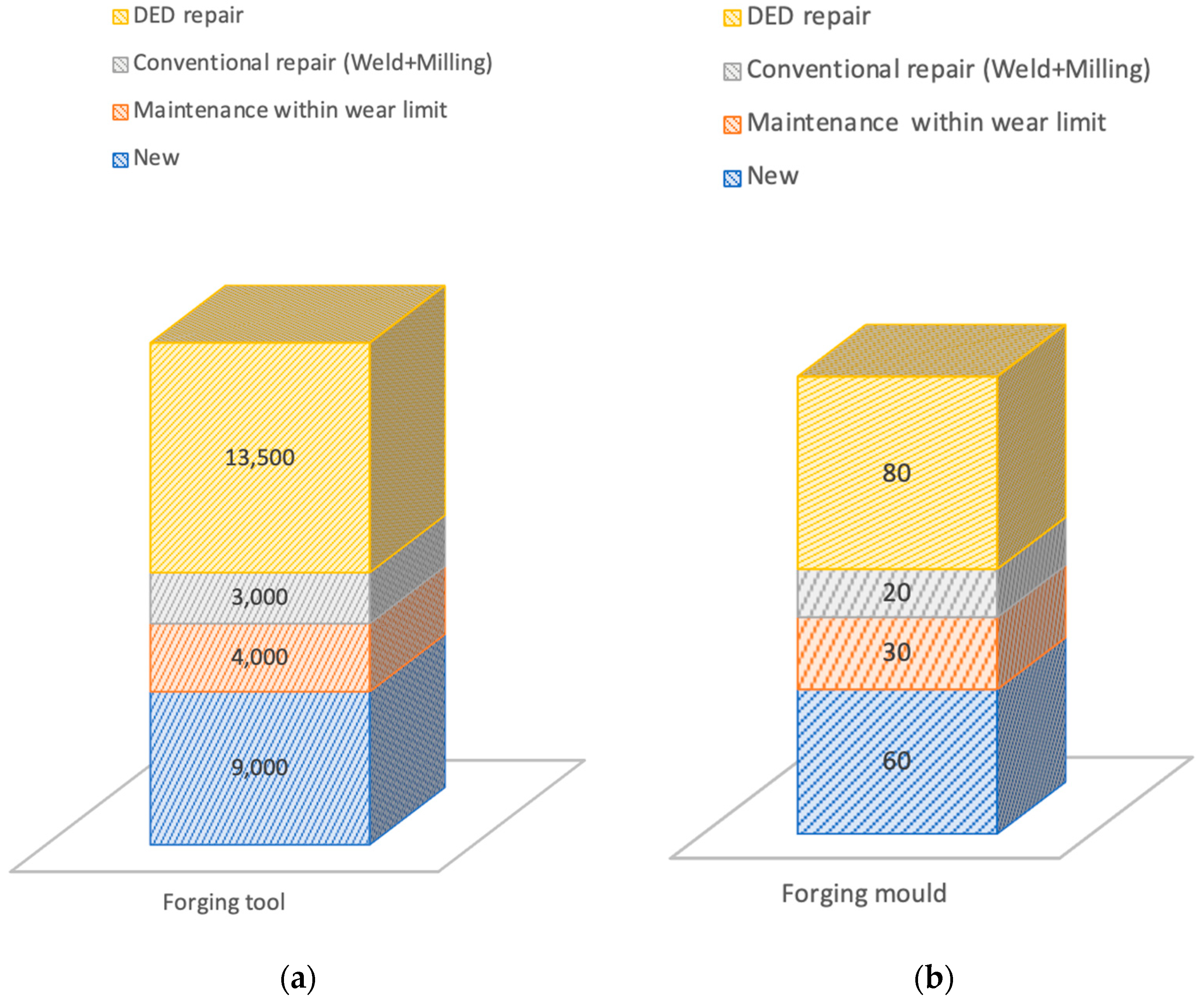
4.3. Repair Process Results and Discussion
The original forging tool demonstrated a lifespan of approximately 9000 parts before necessitating refurbishment, which was achievable solely by finishing the original tool within its wear limit. Post this refurbishment process, the tool’s production capability reduced to around 4000 parts, eventually requiring complete repair. Opting for conventional welding technology (e.g., TIG welding) extended its usability by another 3000 parts. Contrariwise, utilising DED in the repair process increased the tool’s lifespan to approximately 13,500 parts before requiring a total overhaul, as depicted in Figure 26a.
Figure 26.
(a) Number of parts produced at each stage of the forging tool’s lifecycle; (b) number of parts produced at each stage of the forging mould lifecycle.
In the case of the forging mould, utilised solely for prototyping, it initially managed around 60 parts before needing maintenance within the wear interval. Following this initial maintenance, the mould sustained usability for an additional 25 to 30 parts before necessitating a complete overhaul. However, after undergoing repair via the DED process, the mould showcased enhanced performance, being capable of producing approximately 80 parts before requiring maintenance within the wear limit (Figure 26b).
The findings of this research can be extended to various repair procedures involving components enduring torsion and bending loads, which differ from the stress experienced by forging tools and moulds. For instance, consider the repair process of a sheared drive axle coupling zone (Figure 27a). Initially, a thorough analysis of the damaged region was conducted to develop suitable repair strategies.
Figure 27.
(a) Damaged drive shaft; (b) damaged part after DED process; (c) drive shaft after the milling process (finished product).
Once the optimal repair method was determined, careful removal of affected areas containing potential micro fissures was executed, ensuring a compliant repair process without risking the dissipation of cracks in the future deposit base. To prepare the base for deposition, a flat surface was milled. The DED process was utilised, employing a material with close mechanical properties of the shaft while considering the stresses the product will encounter. Upon material deposition and cooling, a comprehensive quality check was performed. This evaluation involves a visual inspection for potential process-induced cracks and any deformations on the deposition base (Figure 27b). In the subsequent phase, mechanical milling operations were employed on the shaft’s front to create its external thread and bore, resulting in the finalised repaired part (Figure 27c).
4.4. Encountered Challenges
The repair process for moulds encountered issues primarily linked to cracks that manifested post the DED process stage [29]. Key factors contributing to these challenges include the choice of material and the parameters of the deposition process.
Among the deposition parameters, the greatest influence is attributed to the parameters defining the dimensions of the deposited layer. If they are not selected according to the specifications proposed by the manufacturer, cracks appear after material deposition. At the same time, cracks can also occur due to selecting a much too high initial laser power (during the deposition of the first layer, which is in contact with the material that makes the base surface) [30,31]. Excessive initial laser power, especially during the deposition of the initial layer interfacing with the base material, can elevate the temperature excessively, inducing thermal expansion and subsequent cracking during cooldown due to different thermal expansion coefficients (Figure 28 and Figure 29a). Moreover, improper laser power settings across the layers or inconsistent settings can result in suboptimal material deposition, increasing the likelihood of cracks. Variations in layer height or irregular nozzle movement speeds may lead to surface irregularities, necessitating the removal of previously deposited material and initiating a new deposition process at an optimal speed.
Figure 28.
Cracks after cooling on mould’s active surface cavity.
Figure 29.
Cracks arising after cooling: (a) delamination of first layer; (b) cracks of layers.
The problems that emerged during the repair process included cracks developed after cooling. They are due to non-observed deposition parameters or the sudden cooling of the deposited material. Incompatibility of the additive material can lead to poor adhesion, resulting in deposition errors or even collisions during the process. Notably, excessive initial power settings could deform the base material, visible through a bluish tint in the base material (Figure 29).
5. Discussion
Based on the results obtained from the mechanical tests and case studies, Table 4 presents a comparative analysis between DED and conventional repair methods, highlighting their respective strengths and weaknesses.
Table 4.
Comparative analysis between conventional repair and DED-based repair methods.
5.1. Layering Strategy
Through this research, it was found that different layering strategies applied for parts repaired using DED hybrid manufacturing can significantly influence the mechanical properties, particularly tensile strength and ductility, of the manufactured components. First, the thickness of each deposited layer plays a crucial role. Thinner layers tend to create finer microstructures, which can enhance mechanical properties like tensile strength due to reduced porosity and improved grain structure [32]. However, excessively thin layers might lead to increased heat accumulation and potential interlayer defects. Excessive heat accumulation involves localised melting and rapid solidification, which can increase the brittleness of the parts and in extreme cases can cause cracks and even delamination of the DED layers. Layer deposition strategies can impact the width and depth of the heat-affected zone in the substrate material, which ultimately impacts the grain growth and microstructure, affecting both strength and ductility. Proper deposition strategy can enhance the bond strength between layers, positively impacting tensile strength. Moreover, rapid cooling after deposition may lead to a higher number of dislocations and grain refinement, potentially enhancing strength but possibly compromising ductility, while slower cooling rates could allow for a more uniform microstructure and better ductility but might negatively impact strength. This behaviour was notably observed in parts manufactured during different ambient temperature conditions—during winter, characterised by lower ambient temperatures in the vicinity of the DED hybrid manufacturing machine, micro fissures were observed in the repaired sections of parts. In contrast, during summer, when the ambient temperature significantly rose, micro fissures were absent in the DED-repaired parts. However, the increased humidity levels during summer led to a quicker onset of rusting for the DED-refurbished parts.
Adequate bonding between layers is also critical. Incomplete fusion or poor bonding can create discontinuities, reducing overall strength. Optimising parameters like laser power, deposition speed, and overlap between successive layers can enhance interlayer bonding, influencing both tensile strength and ductility. Layering also influences the grain orientation and growth. A uniform, fine-grained microstructure generally improves mechanical properties. However, uncontrolled grain growth or orientation due to improper layering strategies might compromise both strength and ductility.
Varying layering strategies can result in different residual stresses within the manufactured component. Controlling these stresses is crucial, as excessive residual stress can lead to cracking or reduced ductility. Strategies like controlled cooling rates or post-processing treatments may diminish these effects.
5.2. Material Compatibility
Material compatibility is a critical aspect when using DED for repairing and optimising existing components. Ensuring that the material used for repair matches the base material is crucial. Differences in material composition, thermal expansion coefficients, or mechanical properties between the base material and the additive material can lead to poor adhesion, cracking, or compromised structural integrity. Selecting the appropriate alloy or material for the DED process becomes a challenge, especially when dealing with a wide range of materials used in forging tools and moulds. The repair material must possess similar characteristics (mechanical, thermal, and chemical) as the original material to maintain the tool’s performance and durability. Material incompatibility can induce thermal stresses during the DED process, causing cracking or delamination between layers or at the interface with the base material. Mismatched thermal properties may result in residual stresses, leading to material failure.
Achieving uniform microstructural properties across the repaired area is necessary, as variations in cooling rates or heat-affected zones during the deposition process might lead to differences in grain structure, which can affect the mechanical properties of the repaired component. DED involves controlling various parameters like laser power, deposition speed, and material feed rate. Material selection influences these parameters, and using materials with significantly different characteristics may require adjustments that affect the overall deposition process and quality.
Considering that material selection and compatibility profoundly impact the repair process, here are most important phases needed for a successful DED repair:
- Pre-repair assessment, where a comprehensive material analysis of the base material is made. This is crucial to understand its composition, structure, and mechanical properties. This information guides the selection of compatible repair materials and helps in defining optimal DED processing parameters.
- Choosing the optimal process parameters is carried out based on the chosen material for repair; the DED process parameters need fine-tuning to ensure proper fusion and adhesion and minimal thermal stress. Parameter adjustments may include laser power, deposition strategy, and deposition speed, among others.
- Continuous monitoring and quality checks during the deposition process and post-repair inspections are critical. Non-destructive testing techniques can help identify any material inconsistencies or structural flaws that might compromise the repaired tool or mould.
- The manufacturing environment (e.g., ambiance temperature and humidity) is an important factor for a successful DED repair process. Thus, despite meticulous planning, some degree of trial and error might be necessary, especially when dealing with novel materials or complex geometries. Iterative testing and adjustments may be required to achieve the desired material compatibility and quality.
Overall, material selection and compatibility heavily influence the success of the repair process using DED.
6. Limitations
This study presents the impact of different heights and build levels on the mechanical properties of DED-manufactured specimens. However, the orientation of these specimens remains unexplored. Acknowledging the significance of build orientation in additive manufacturing processes [33], this study, focused on layer-specific effects, did not encompass the influence of specimen orientation on the mechanical attributes. Future investigations considering specimens’ build orientation could offer a more comprehensive understanding of DED-manufactured part properties.
Utilising a diverse range of materials is fundamental in evaluating DED’s efficiency across various metal types. This study, conducted within an industrial site and focused on specific case studies, utilised X2CrNiMo17-13-2 metal powder exclusively for experimentation. Expanding material variations would improve the analysis of DED’s performance across different alloys and metals. However, the limited accessibility to multiple materials within the industrial context constrained the exploration to a single alloy which was compatible with the base material.
While the study primarily emphasises tensile properties, future investigations could encompass a broader range of mechanical tests. Including tests such as flexural and compression tests would offer a more complete analysis of how layering affects the mechanical attributes of DED-manufactured parts. These additional tests could provide insights into the behaviour of DED components under various loading conditions.
The constraints in material diversity, orientation analysis, and the need for a wider range of mechanical tests are recognised as limitations in this study. Addressing these aspects in future research could contribute significantly to a more complete understanding of DED manufacturing and its mechanical implications across diverse scenarios and materials.
7. Conclusions
This study investigates the implications of employing directed energy deposition (DED) processes for repairing forging tools and moulds. The comparison between specimens fabricated through conventional sheet metal and those formed via DED processes was conducted to establish the superior mechanical properties offered by the latter. This experimental study of the mechanical properties of materials manufactured by subtractive and hybrid processes yielded crucial insights. Subtractive processes, exemplified by laser-cut stainless steel, exhibited higher elongation at lower stress levels, indicating a more ductile nature under tension. Conversely, specimens produced via the DED process displayed a distinct pattern, showing higher stress and lower strain, highly influenced by the layer level of the DED deposition.
The scatter plot’s observed trends in stress and % strain highlight distinct mechanical properties between subtractive and hybrid manufacturing specimens. The DED process showcased layer-dependent behaviours associated with different deposition levels. While the highest level (DED L1) demonstrated lower tensile strength but higher elongation, indicative of enhanced ductility, the initial level (DED L3) displayed the highest tensile strength but exhibited a more brittle nature. Notably, the middle layers (DED L2), enduring the most prolonged exposure to heat, demonstrated median tensile strength but relatively lower elongation, indicating a brittle behaviour influenced by prolonged heat retention. This analysis highlights the crucial influence of DED’s layering levels on resultant material properties, emphasising the compromise between strength and ductility.
In the context of repairing metal forging tools and moulds, the hybrid repair approach, merging DED and CNC machining, served as a reliable solution for severe damage. This method not only restored critical components for mass production and high-stress applications, but also ensured precision and reliability, outperforming conventional repair methods.
However, encountered issues during the repair process highlighted the significance of meticulous parameter control in the DED process. Factors such as initial laser power, layer dimensions, and material compatibility played pivotal roles. Deviations from optimal parameters often led to crack formations post-cooling, emphasising the criticality of adhering to manufacturer specifications for successful material deposition.
Ultimately, this study underscores the potential of hybrid repair methods in repairing damaged forging tools and moulds for extended operational lifespans. However, a comprehensive understanding of deposition parameters remains essential in justifying post-process issues and ensuring the optimal performance of repaired components.
Author Contributions
Conceptualisation, R.E.P.; methodology, R.E.P.; investigation, M.-C.L.; resources, M.-C.L.; writing—original draft preparation, R.E.P. and M.-C.L.; writing—review and editing, R.E.P. and M.-C.L.; funding acquisition, R.E.P. All authors have read and agreed to the published version of the manuscript.
Funding
This research was funded by Lucian Blaga University of Sibiu through the research grant LBUS-IRG-2022-08.
Institutional Review Board Statement
Not applicable.
Informed Consent Statement
Not applicable.
Data Availability Statement
The data presented in this study are available on request from the corresponding author. The data are not publicly available due to restrictions.
Acknowledgments
We acknowledge the support given by Compa SA company and Eng. Banu Lucian Florin, Eng. Burtic Florin Alin, and Eng. Ilioiu Constantin Gabriel, which contributed to the specimen fabrication and mould and tool repair process.
Conflicts of Interest
The authors declare no conflict of interest.
References
- Gebhardt, A.; Hötter, J.-S. Additive Manufacturing 3D Printing for Prototyping and Manufacturing; Carl Hanser Verlag GmbH Co KG: Munich, Germany, 2016; ISBN 978-1-56990-582-1. [Google Scholar]
- Dilberoglu, U.M.; Gharehpapagh, B.; Yaman, U.; Dolen, M. Current Trends and Research Opportunities in Hybrid Additive Manufacturing. Int. J. Adv. Manuf. Technol. 2021, 113, 623–648. [Google Scholar] [CrossRef]
- Gradl, P.R.; Mireles, O.R.; Protz, C.S.; Garcia, C.P. (Eds.) Metal Additive Manufacturing for Propulsion Applications; American Institute of Aeronautics and Astronautics, Inc.: Reston, VA, USA, 2022; ISBN 978-1-62410-626-2. [Google Scholar]
- Pontes, A.J. Designing for Additive Manufacturing. In Design and Manufacturing of Plastics Products; Elsevier: Amsterdam, The Netherlands, 2021; pp. 249–292. ISBN 978-0-12-819775-2. [Google Scholar]
- Palmero, E.M.; Bollero, A. 3D and 4D Printing of Functional and Smart Composite Materials. In Encyclopedia of Materials: Composites; Elsevier: Amsterdam, The Netherlands, 2021; pp. 402–419. ISBN 978-0-12-819731-8. [Google Scholar]
- Izdebska-Podsiadły, J. Classification of 3D Printing Methods. In Polymers for 3D Printing; Elsevier: Amsterdam, The Netherlands, 2022; pp. 23–34. ISBN 978-0-12-818311-3. [Google Scholar]
- Özel, T.; Shokri, H.; Loizeau, R. A Review on Wire-Fed Directed Energy Deposition Based Metal Additive Manufacturing. J. Manuf. Mater. Process. 2023, 7, 45. [Google Scholar] [CrossRef]
- Ahn, D.-G. Directed Energy Deposition (DED) Process: State of the Art. Int. J. Precis. Eng. Manuf.-Green Technol. 2021, 8, 703–742. [Google Scholar] [CrossRef]
- Dutta, B. Directed Energy Deposition (DED) Technology. In Encyclopedia of Materials: Metals and Alloys; Elsevier: Amsterdam, The Netherlands, 2022; pp. 66–84. ISBN 978-0-12-819733-2. [Google Scholar]
- Asnafi, N. Tool and Die Making, Surface Treatment, and Repair by Laser-Based Additive Processes. BHM Berg- Hüttenmänn. Monatshefte 2021, 166, 225–236. [Google Scholar] [CrossRef]
- Asnafi, N.; Rajalampi, J.; Aspenberg, D.; Alveflo, A. Production Tools Made by Additive Manufacturing Through Laser-Based Powder Bed Fusion. BHM Berg- Hüttenmänn. Monatshefte 2020, 165, 125–136. [Google Scholar] [CrossRef]
- Yusoh, S.S.M.; Wahab, D.A.; Habeeb, H.A.; Azman, A.H. Intelligent Systems for Additive Manufacturing-Based Repair in Remanufacturing: A Systematic Review of Its Potential. PeerJ Comput. Sci. 2021, 7, e808. [Google Scholar] [CrossRef] [PubMed]
- Džugan, J.; Novy, Z. Powder Application in Additive Manufacturing of Metallic Parts. In Powder Metallurgy—Fundamentals and Case Studies; Dobrzanski, L.A., Ed.; InTech: London, UK, 2017; ISBN 978-953-51-3053-6. [Google Scholar]
- Volyanskii, I.; Shishkovsky, I.V. Laser-Assisted 3D Printing of Functional Graded Structures from Polymer Covered Nanocomposites: A Self-Review. In New Trends in 3D Printing; Shishkovsky, I.V., Ed.; InTech: London, UK, 2016; ISBN 978-953-51-2479-5. [Google Scholar]
- Dávila, J.L.; Neto, P.I.; Noritomi, P.Y.; Coelho, R.T.; da Silva, J.V.L. Hybrid Manufacturing: A Review of the Synergy between Directed Energy Deposition and Subtractive Processes. Int. J. Adv. Manuf. Technol. 2020, 110, 3377–3390. [Google Scholar] [CrossRef]
- E28 Committee. Test Methods for Tension Testing of Metallic Materials; ASTM International: West Conshohocken, PA, USA, 2011. [Google Scholar]
- Shim, D.-S.; Baek, G.-Y.; Seo, J.-S.; Shin, G.-Y.; Kim, K.-P.; Lee, K.-Y. Effect of Layer Thickness Setting on Deposition Characteristics in Direct Energy Deposition (DED) Process. Opt. Laser Technol. 2016, 86, 69–78. [Google Scholar] [CrossRef]
- F42 Committee. Standard Guide for Directed Energy Deposition of Metals; ASTM International: West Conshohocken, PA, USA, 2016. [Google Scholar]
- Zhang, W.; Soshi, M.; Yamazaki, K. Development of an Additive and Subtractive Hybrid Manufacturing Process Planning Strategy of Planar Surface for Productivity and Geometric Accuracy. Int. J. Adv. Manuf. Technol. 2020, 109, 1479–1491. [Google Scholar] [CrossRef]
- Kistler, N.A.; Nassar, A.R.; Reutzel, E.W.; Corbin, D.J.; Beese, A.M. Effect of Directed Energy Deposition Processing Parameters on Laser Deposited Inconel® 718: Microstructure, Fusion Zone Morphology, and Hardness. J. Laser Appl. 2017, 29, 022005. [Google Scholar] [CrossRef]
- Kim, T.G.; Shim, D.S. Effect of Laser Power and Powder Feed Rate on Interfacial Crack and Mechanical/Microstructural Characterizations in Repairing of 630 Stainless Steel Using Direct Energy Deposition. Mater. Sci. Eng. A 2021, 828, 142004. [Google Scholar] [CrossRef]
- Era, I.Z. Prediction of Tensile Behaviors of L-DED 316 Stainless Steel Parts Using Machine Learning; MS, West Virginia University Libraries: Morgantown, West Virginia, 2021. [Google Scholar]
- Saboori, A.; Aversa, A.; Marchese, G.; Biamino, S.; Lombardi, M.; Fino, P. Microstructure and Mechanical Properties of AISI 316L Produced by Directed Energy Deposition-Based Additive Manufacturing: A Review. Appl. Sci. 2020, 10, 3310. [Google Scholar] [CrossRef]
- Su, Y.; Wang, Y.; Shi, J. Microstructure and Mechanical Properties of Laser DED Produced Crack-Free Al 7075 Alloy: Effect of Process Parameters and Heat Treatment. Mater. Sci. Eng. A 2022, 857, 144075. [Google Scholar] [CrossRef]
- Ramiro, P.; Ortiz, M.; Alberdi, A.; Lamikiz, A. Strategy Development for the Manufacturing of Multilayered Structures of Variable Thickness of Ni-Based Alloy 718 by Powder-Fed Directed Energy Deposition. Metals 2020, 10, 1280. [Google Scholar] [CrossRef]
- D’Souza, N.; Ravichandran, S.; Donovan, S.; Daum, P.; Morrell, R.; Nye, Z.; Lancaster, R.J. On the Design Optimisation of Direct Energy Deposited Support Structures to Repair Aero-Engine Turbine Segments. Addit. Manuf. 2022, 56, 102905. [Google Scholar] [CrossRef]
- Keshavarz, M.K.; Gontcharov, A.; Lowden, P.; Chan, A.; Kulkarni, D.; Brochu, M. Turbine Blade Tip Repair by Laser Directed Energy Deposition Additive Manufacturing Using a Rene 142–MERL 72 Powder Blend. J. Manuf. Mater. Process. 2021, 5, 21. [Google Scholar] [CrossRef]
- Foster, J.; Cullen, C.; Fitzpatrick, S.; Payne, G.; Hall, L.; Marashi, J. Remanufacture of Hot Forging Tools and Dies Using Laser Metal Deposition with Powder and a Hard-Facing Alloy Stellite 21®. J. Remanufacturing 2019, 9, 189–203. [Google Scholar] [CrossRef]
- Elshaer, R.N.; Elshazli, A.M.; Hussein, A.H.A.; Al-Sayed, S.R. Impact of Laser Process Parameters in Direct Energy Deposition on Microstructure, Layer Characteristics, and Microhardness of TC21 Alloy. Int. J. Adv. Manuf. Technol. 2022, 121, 5139–5154. [Google Scholar] [CrossRef]
- Behlau, F.; Thiele, M.; Maack, P.; Esen, C.; Ostendorf, A. Layer Thickness Controlling in Direct Energy Deposition Process by Adjusting the Powder Flow Rate. Procedia CIRP 2022, 111, 330–334. [Google Scholar] [CrossRef]
- Pan, T. Influence of Input Energy on Mechanical Properties of Laser Powder Bed Fused AISI 304L Stainless Steel; Missouri University of Science and Technology: Rolla, Missouri, 2020. [Google Scholar]
- Ribeiro, K.S.B.; Mariani, F.E.; Coelho, R.T. A Study of Different Deposition Strategies in Direct Energy Deposition (DED) Processes. Procedia Manuf. 2020, 48, 663–670. [Google Scholar] [CrossRef]
- Kersten, S.; Praniewicz, M.; Kurfess, T.; Saldana, C. Build Orientation Effects on Mechanical Properties of 316SS Components Produced by Directed Energy Deposition. Procedia Manuf. 2020, 48, 730–736. [Google Scholar] [CrossRef]
Disclaimer/Publisher’s Note: The statements, opinions and data contained in all publications are solely those of the individual author(s) and contributor(s) and not of MDPI and/or the editor(s). MDPI and/or the editor(s) disclaim responsibility for any injury to people or property resulting from any ideas, methods, instructions or products referred to in the content. |
© 2024 by the authors. Licensee MDPI, Basel, Switzerland. This article is an open access article distributed under the terms and conditions of the Creative Commons Attribution (CC BY) license (https://creativecommons.org/licenses/by/4.0/).


