1. Introduction
Hydrogen has sparked interest as an alternative source to facilitate the transition to a cleaner energy landscape. Hydrogen is an excellent energy carrier that can mitigate the intermittence challenge with renewable sources by storing surplus energy and releasing it during periods of high demand. However, one of the most pressing challenges in realizing the full potential of the hydrogen economy lies in finding effective long-term storage solutions that can accommodate large volumes of hydrogen. It is within this context that the motivation for subsurface storage solutions arises, aiming to store hydrogen at grid-scale levels. On that note, capacity assessment is a pivotal initial step in evaluating the viability of potential storage sites. This paper introduces a simple analytical method based on the principles of mass conservation and the real gas law to address this essential aspect of hydrogen storage evaluation in depleted gas reservoirs.
Analytical methods offer a robust and quick alternative to more complex and time-consuming numerical simulations. When these methods are carefully designed and rigorously validated, they become highly effective, particularly in the initial evaluation of potential projects. Their simplicity and efficiency make them powerful tools for early-stage assessments, where quick and accurate insights are essential for informed decision-making. Additionally, analytical methods can provide a strong foundation for more detailed analyses, guiding the development of comprehensive strategies without the immediate need for complex and resource-intensive simulations. The material balance equation (MBE) is one of the analytical methods most used in the petroleum industry and is currently applied to energy transition applications evaluating the underground storage of carbon dioxide and hydrogen.
The material balance equation is one of the applications of the principle of mass conservation. It was first introduced by Schilthuis [
1] and has been one of the fundamental tools in the oil and gas reservoir engineering discipline ever since [
2]. Despite its name, the MBE introduced by Schilthuis is based on volume conservation and is described as a volumetric material balance by Dake [
3]. It has a wide array of applications, such as estimation of original hydrocarbon reserves, forecasting reservoir pressure, estimation of water influx, identification of reservoir drive mechanism, history matching, etc. [
4,
5]. In this paper, we explore the application of the material balance equation to estimate hydrogen storage capacity in a depleted dry gas reservoir.
It is worth mentioning that dry gas reservoirs primarily contain methane and brine with negligible amounts of other hydrocarbons. This high methane content simplifies analytical modeling, as it can be assumed that methane is the only component of natural gas. Furthermore, dry gas reservoirs maintain a single hydrocarbon phase throughout the reservoir’s lifespan [
6]. Some sources suggest that material balance calculations for dry gas reservoirs can also be applied to wet gas reservoirs since they also remain in a single hydrocarbon phase. However, modeling the phase behavior of wet gas reservoirs requires additional considerations due to the presence of other light hydrocarbons alongside methane [
6,
7].
The proposed methodology is validated through numerical simulation of a tank model representing a depletion drive and a water drive gas reservoir. Next, the methodology is illustrated through a theoretical case study of a complex heterogeneous reservoir, demonstrating its practical application in hydrogen storage assessment.
3. Methodology
The mathematical formulation of the material balance equation is adapted from He et al. [
22]. It is based on the mass conservation principle in an idealized representation of a gas reservoir as a container. For simplicity, methane (CH
4) is considered the sole constituent of the natural gas in the reservoir. Also, we assume constant reservoir temperature in this study.
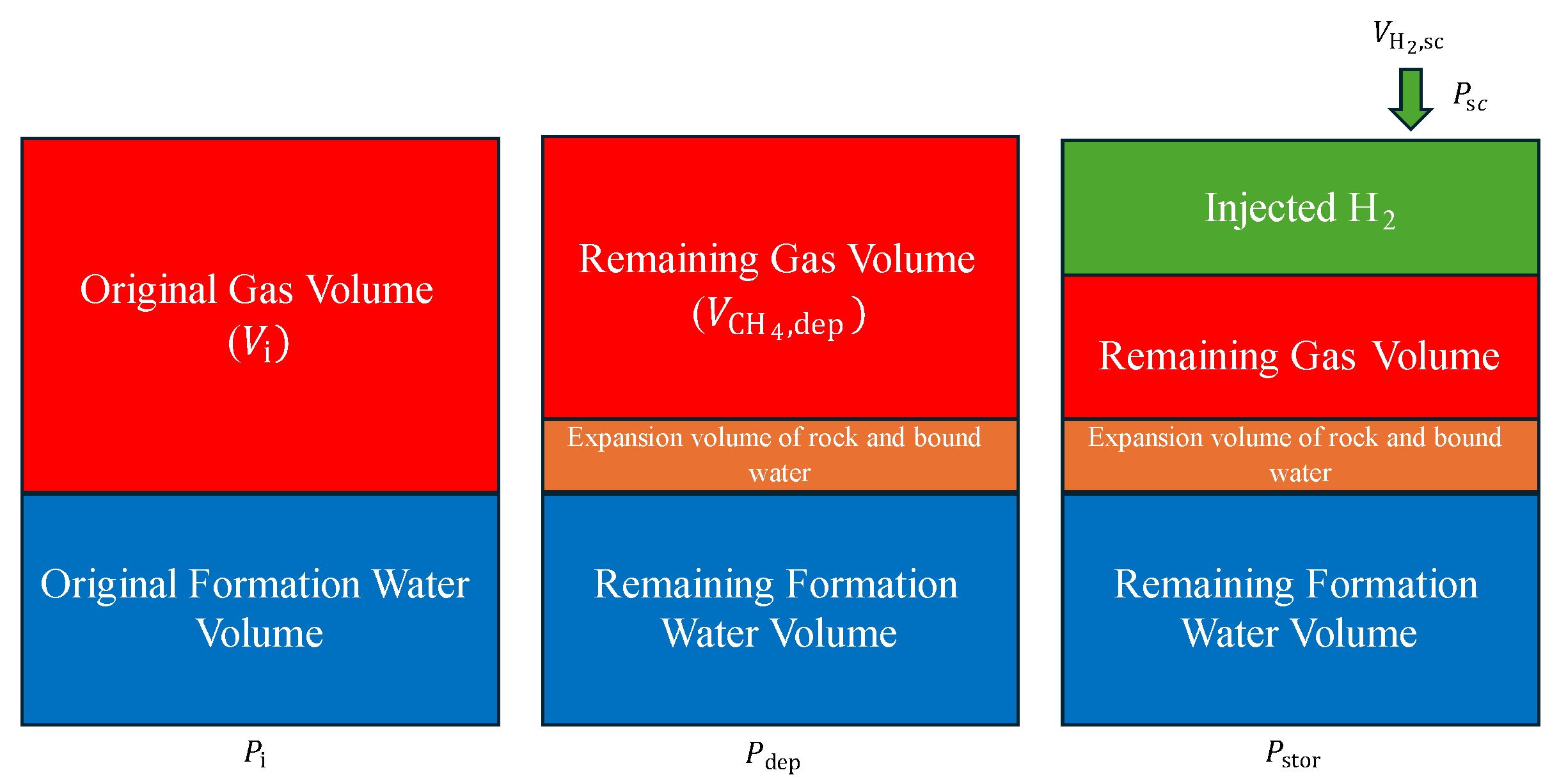
Figure 1 shows a schematic representation of the system. The objective is to establish a macroscopic mass balance relationship using a zero-dimensional (tank) model, following the material balance frameworks described by Fuentes-Cruz and Vasquez-Cruz [
4] and Zhang and Ayala [
33]. This approach correlates the initial fluid in place volumes with variables such as reservoir pressure, injected fluids, aquifer influx, and the compressibility of rock and water. This is performed by using average properties and disregarding internal gradients of pressure and temperature, providing a simplified yet effective representation of the storage reservoir. The proposed analytical framework is implemented in Python and can be downloaded from the
Supplementary Material. The in situ gas PVT (pressure, volume, temperature) properties are computed utilizing the Soave–Redlich–Kwong (SRK) [
34] equation of state (EoS) from the open-source thermodynamic library CoolProp [
35]. However, it is important to mention that the framework presented can be used with any other EoS or constitutive relation that provides the gas phase compressibility factor. A mass balance equation is formulated for each gas in the system on the following basis:
where the subscript dep denotes depletion conditions, sc is for surface conditions, and stor is for reservoir storage conditions.
Based on the real gas law (
pV =
ZnRT), the molar quantity of methane in Equation (1) can be written as
where
pdep is the depletion pressure [psi],
is the remaining gas volume at depletion conditions [ft
3],
is the gas compressibility factor at depletion conditions,
Tdep is the reservoir temperature [°R], and
R is the universal gas constant 10.73 [psi·ft
3·lbmol
−1·°R
−1].
The gas-bearing pore volume
V [ft
3], at any point in time, can be expressed as
where
Vi is the initial pore volume [ft
3],
ceff is the effective compressibility [1/psi],
pi is the initial reservoir pressure [psi],
p is the reservoir pressure [psi] at any point in time,
Wp is the volume of produced water [STB],
Bw is the water formation volume factor [bbl/STB],
We is the water influx [bbl], and 5.615 is the unit conversion factor [ft
3/bbl].
The initial gas pore volume
Vi [ft
3] is expressed as
where
Gi is the initial gas in place [SCF], and
Bgi is the gas formation volume factor at the reservoir’s initial conditions [ft
3/SCF].
If the initial gas in place
Gi [SCF] is unknown; the initial gas pore volume
Vi [ft
3] can be calculated by
where
A is the reservoir area [ft
2],
h is the reservoir thickness [ft],
is porosity [fraction], and
Swi is the initial water saturation [fraction].
The effective compressibility
ceff [1/psi], accounting for both rock and gas expansion with pressure change as defined by Ahmed et al. [
5], is expressed as
where
cf is the formation compressibility [1/psi] and
cw is the water compressibility [1/psi].
Hydrogen mixes with methane after injection; therefore, we can express the total gas moles in the pore space with
where
pstor is the storage pressure [psi],
Vg,stor is the total gas volume in the pore space [ft
3],
Zg,stor is the gas mixture compressibility factor,
Tstor is the reservoir temperature [°R], and
R is the universal gas constant 10.73 [psi·ft
3·lbmol
−1·°R
−1].
The total moles of gas at storage conditions can also be expressed as
where
is the moles of methane at storage conditions [lbmol], and
is the moles of hydrogen at storage conditions [lbmol].
Based on the conservation of mass relation formulated in Equation (1), the molar quantity of methane is constant, i.e., , which was estimated using Equation (3). Therefore, we can solve for the molar quantity of hydrogen, , in two ways:
- 2.
By introducing the molar fraction :
Rearranging the equation:
Finally, the surface volume of hydrogen can be computed from the moles of hydrogen using the real gas law as follows:
The following steps demonstrate the iterative approach to estimating the injected hydrogen volume for storage :
Determine the pore volume occupied by methane, , using Equation (4) at depletion conditions.
Compute the molar quantity of methane, , using Equation (3).
Start with an initial guess for the hydrogen mole fraction, , such that .
Using the initial (or updated) guess, calculate the compressibility factor, Zg,stor, for the gas mixture.
Determine the pore volume occupied by the total gas mixture, Vg,stor, using Equation (4) at storage condition.
Calculate the total gas moles, ngt, using Equation (8).
Calculate the hydrogen moles, , using Equations (10) and (12).
Check for convergence ( from Equation (10) = from Equation (12)).
If convergence is not reached, update guess with the hydrogen moles from Equation (10):
- 10.
Return to Step 4 and repeat.
- 11.
Once convergence is achieved, calculate hydrogen storage capacity, , using Equation (13).
The above steps are summarized in a flowchart diagram, as illustrated in
Figure 2.
4. Verification with Numerical Simulation of a Tank Model
In this section, we verify the proposed methodology by constructing a simple tank model consisting of a single grid block with a single well, as shown in
Figure 3. It is important to note that the tank model approach is widely used in petroleum engineering, and there is extensive literature comparing its performance with numerical simulation, demonstrating its usefulness, limitations, and how it can be modified for various purposes; example references are provided [
15,
33,
36,
37,
38,
39,
40,
41]. The verification is conducted for two cases: depletion/volumetric drive gas reservoir and water drive gas reservoir using the commercial compositional reservoir simulator CMG GEM [
42]. The governing equations for compositional simulators are comprised of a complex system of partial differential equations (associated with the material balance of each component or pseudo-component in the system), along with thermodynamic relationships and correlations to model fluid properties and phase equilibrium [
43]. Zhang and Ayala [
33] demonstrated how the zero-dimensional MBE can be derived from the governing partial differential equation used in numerical simulation, which is expressed as follows:
where
and
are the densities of the gas and liquid phase,
and
are the gas and liquid velocities, and
yi and
xi are the mole fraction of component i in the gas phase and liquid phase, respectively. Finally,
qi is the injection/production rate per unit volume of component
i. When a single gridblock is considered and assuming no flow through the boundaries, the term on the left-hand side of Equation (14) becomes zero, and the material balance becomes a relationship between injection/production and the fluid in place.
Odeh [
44] describes the tank model as the fundamental component of reservoir simulators, where the rock and fluid properties do not exhibit any spatial variation. This makes it an ideal verification tool for the zero-order material balance equation (MBE). The verification is performed by comparing the resulting gas mixture compressibility factor, hydrogen molar fraction, and the volume of injected hydrogen at surface conditions. The parameters used to design this model were selected based on typical values encountered in the field. It is important to mention that the purpose of this verification exercise is to ensure that the MBE proposed in this work is mathematically accurate. A benchmark of the proposed MBE and a numerical solution considering a reservoir model with typical multidimensional discretization is presented later to investigate how the proposed MBE performs when mass and heat transfer within the porous formation is considered.
Table 1 summarizes the model properties and indicates which ones are required as inputs for the Python code. The initial pore volume can be calculated using Equation (5) or Equation (6). Hence, the (if applicable) note in
Table 1. In this exercise, we opted to calculate it using Equation (6).
One of the most important considerations in this study is ensuring representative modeling of the phase behavior of the hydrogen–methane mixture. Accurately capturing fluid behavior is critical because it influences numerous factors such as density, compressibility, and the overall mixture behavior under varying pressure and temperature conditions. Huang et al. [
45] conducted a comparison of the performance of three equation-of-state (EOS) models in matching experimental data of the binary hydrogen–methane gas mixture density at different mole fractions, which were obtained from Hernandez-Gomez et al. [
46]. The three EOS models analyzed were the Peng–Robinson EOS [
47], Soave–Redlich–Kwong EOS [
34], and the GERG-2008 model [
48]. The results showed that the GERG-2008 model exactly matched the experimental data. However, it is less computationally efficient due to its mathematical complexity. On the other hand, the SRK EOS demonstrated excellent accuracy, significantly outperforming the PR EOS. Based on these findings, we opted to proceed with the SRK EOS to calculate the gas compressibility factor and density for this study. In addition, Jossi et al.’s [
49] model was used to calculate the gas viscosity.
It is important to note that this study focused on assessing the total capacity for hydrogen storage. Consequently, we did not evaluate the required quantity of cushion gas or the resulting working gas. Additionally, we did not consider the impact of geochemical reactions on hydrogen losses or formation alteration. Furthermore, the solubility of hydrogen in water, molecular diffusion, and hydrodynamic dispersion are not accounted for in this assessment since their impact is more important in deliverability evaluation.
4.1. Volumetric-Drive Gas Reservoir
Volumetric gas reservoirs exhibit no water encroachment and negligible water production, which cancels out the water influx
We and water production
WpBw in Equation (4). This type of reservoir is depleted by gas expansion, which is solely controlled by pressure. In addition, it is typical to recover 80–90% of the original gas in place in this type of gas reservoir [
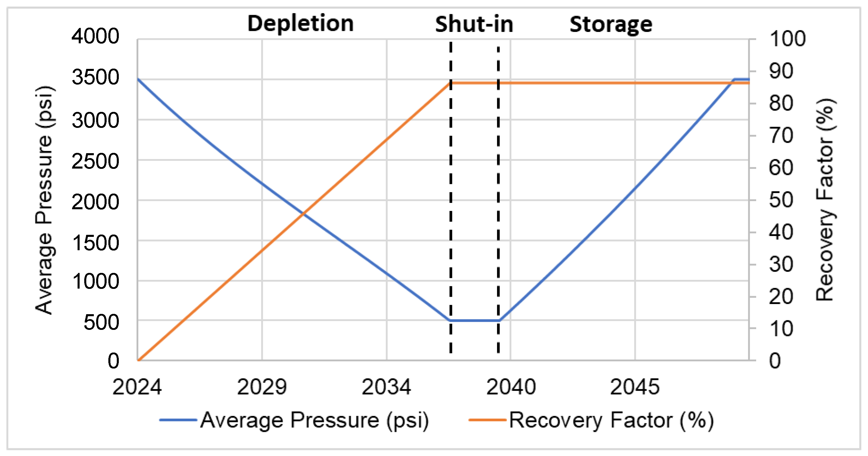
5]. To model this case, we set the minimum bottom hole pressure to 500 psi. After 13 years of production, the abandonment pressure is reached, and 87% of the original gas in place is recovered. Next, hydrogen is injected following a 2-year shut-in period until the initial reservoir pressure is reached, as shown in
Figure 4.
In subsurface gas storage, the theoretical capacity is often defined as the maximum storage capacity limit, which has various interpretations based on pore space accessibility [
20]. One possible estimation of this upper limit is charging the reservoir from depletion pressure to the initial reservoir pressure [
17]. Thus, the maximum bottom hole pressure is equal to the initial reservoir pressure in this case to simulate the maximum capacity for hydrogen storage.
The first step in the verification process is to translate the numerical simulation parameters to input parameters for the material balance code in Python. In addition to the inputs indicated in
Table 1, the depletion or abandonment pressure is required, and a range of pressure values in between to evaluate the storage capacity under varying conditions. Once all the parameters are inputted, the code performs the iterative MBE calculation until convergence is achieved. The outputs of the code are reported in
Table 2.
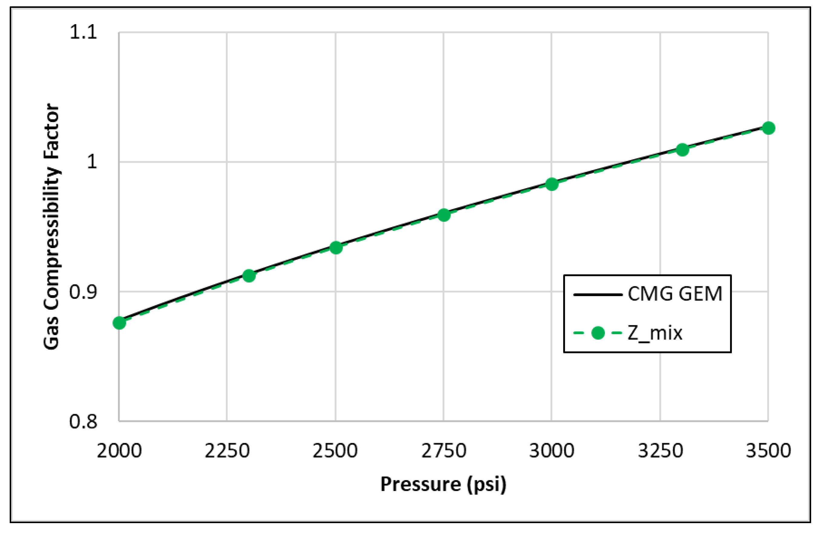
The gas compressibility factors calculated from the numerical simulation and the Python code are compared to ensure consistent and accurate results. This verification step is crucial for validating the reliability of the Python code and the underlying thermodynamic models used. As illustrated in
Figure 5, the compressibility factor calculated in both methods is consistent.
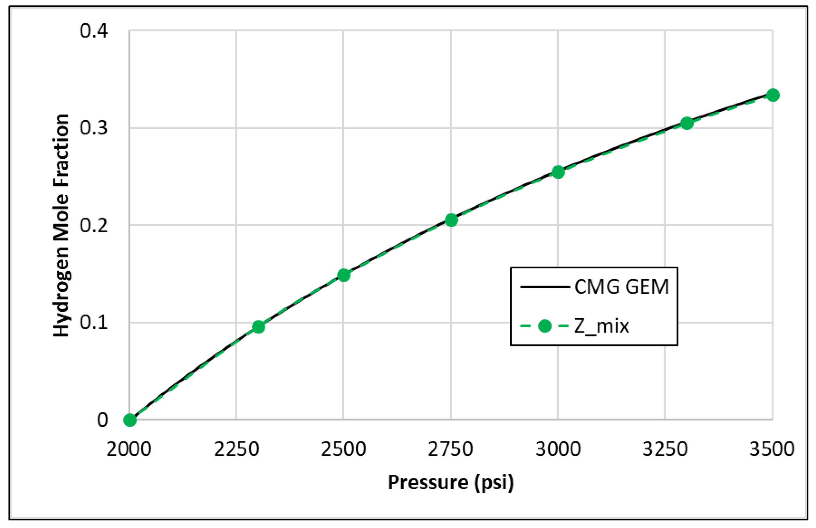
The next parameter compared is the hydrogen molar fraction,
, calculated in both methods. As illustrated in
Figure 6, the hydrogen molar fraction calculated by the code matches the simulation output, further validating the effectiveness of the proposed framework.
Lastly,
Table 3 reports the resulting storage capacity represented by the injected hydrogen volume at surface conditions,
, from the simulator and the proposed MBE approach at different pressure values ranging from the depletion pressure to the initial reservoir pressure. The percentage error between the MBE and simulation results is computed using the following formula:
The results indicate that the proposed MBE framework closely matches the numerical simulation across the entire range of pressures, with an average percentage error of 0.05%. This high level of accuracy demonstrates the robustness of the proposed methodology in estimating hydrogen storage capacity in depleted gas reservoirs.
It is challenging to pinpoint the exact source of error since the numerical simulator and the EoS package used in our framework are both black boxes. However, some potential sources for this minor discrepancy may include roundoff errors, the precision used (single vs. double precision), the method for solving the cubic EOS polynomial, and Newton’s method convergence. Nonetheless, this minimal deviation is within an acceptable range for analytical purposes and does not compromise the robustness of the implemented framework.
4.2. Water-Drive Gas Reservoir
Water-drive gas reservoirs are characterized by an active aquifer, causing water encroachment as the reservoir is depleted. Consequently, the pressure in such reservoirs does not decline as much as in volumetric gas reservoirs. Additionally, gas production is significantly hindered by water coning, resulting in a recovery factor ranging between 50 and 80% [
5].
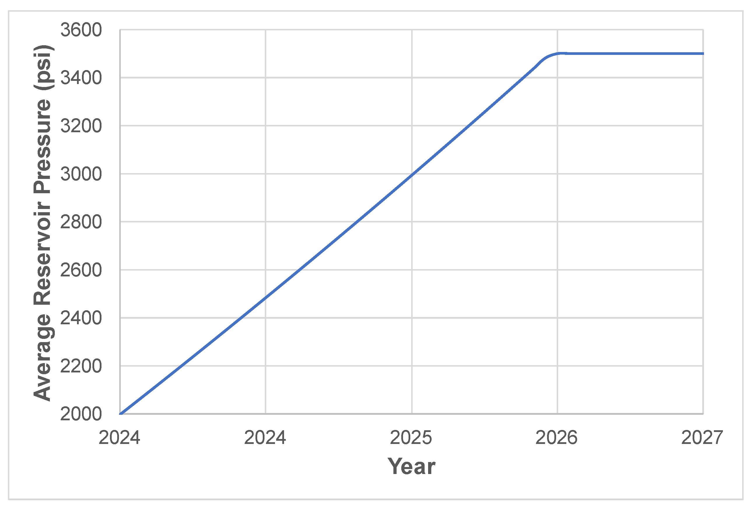
To test the performance of the proposed MBE methodology on this type of reservoir, we initialized the tank model as a gas reservoir that has been depleted with a 63% recovery factor and has been encroached upon by the aquifer. Therefore, the water saturation in this case is set at 50%, and the reservoir pressure is set at 2000 psi. Hydrogen is immediately injected at the start of the simulation run until the initial reservoir pressure of the tank model 3500 psi is reached.
Figure 7 illustrates the increase in pressure during the storage period.
The next step is translating the simulation conditions to inputs for the MBE. The produced water volume,
Wp, and the aquifer influx volume,
We, are set to arbitrary values such that their total equals the change in reservoir water volume after depletion. The change in reservoir water volume, Δ
Vw, is calculated from the change in pore volume using Equation (6) at the initial water saturation in the original tank model and the final water saturation of the depletion case tank model as follows:
Table 4 summarizes the resulting MBE inputs used for this case. The outputs for this case are reported in
Table 5.
The first variable examined for the verification is the gas mixture compressibility factor.
Figure 8 compares the compressibility factors calculated using the Python code and those obtained from the numerical simulator. Despite the complexity introduced by the two-phase flow, which includes gas and water in the system, the compressibility factor computation is not compromised, with results that are extremely close to those generated by the simulator.
The presence of water typically complicates the calculations due to the interactions between the gas and liquid phases, as well as the changes in the overall mixture’s properties. Nonetheless, there is an excellent agreement between the analytical framework and the numerical simulation output of hydrogen mole fraction, as shown in
Figure 9.
Lastly, the injected hydrogen volume (
) is compared in
Table 6. The results show good agreement between the analytical framework and the numerical simulator. The percentage error is higher than the volumetric reservoir case due to the added layer of complexity with the two-phase flow of gas/water. Nonetheless, the average percentage error is 0.67%, which is remarkable given the simplicity of the proposed analytical framework.
5. Case Study
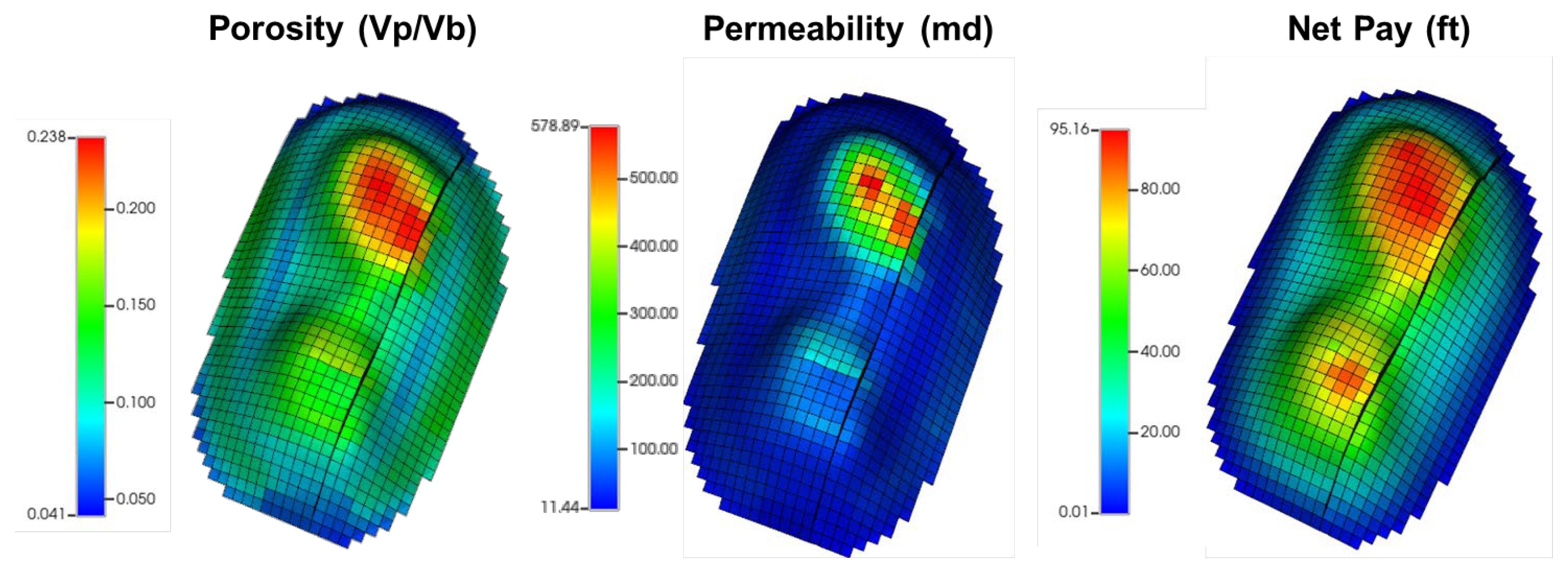
In this section, we illustrate the practical application of the validated MBE analytical framework on a large-scale reservoir. The numerical simulation is performed on a synthetic model representing a heterogeneous volumetric gas reservoir (
Figure 10). This methodology was applied only to volumetric gas reservoirs since modeling water-drive gas reservoirs is more challenging. There are numerous options for modeling the aquifer, leading to a nonunique solution. Without history-matched field data, it is challenging to determine the appropriate aquifer modeling approach. Therefore, the focus on volumetric gas reservoirs ensures a more controlled and reliable application of the proposed methodology.
Table 7 summarizes the model properties.
To model this case, we set the minimum bottom hole pressure to 500 psi. After 25 years of production, the abandonment pressure was reached, and 85% of the original gas in place was recovered. Next, the field was shut in for 5 years before commencing hydrogen injection. The maximum bottom hole pressure was equal to the initial reservoir to simulate the maximum capacity for hydrogen storage. Hydrogen was injected through two wells located in each of the domes in the model.
We input the required data into the MBE Framework code and compared the obtained results with the simulation output, as reported in
Table 8.
With an average error of 0.82%, the close match between the MBE and the simulator results supports using the proposed framework for further analysis and practical applications in underground hydrogen storage.
The slight discrepancies between the MBE and simulation results can be attributed to minor numerical approximations inherent in both methods. However, the low percentage error suggests that these discrepancies are negligible, reinforcing the reliability of this analytical framework for practical applications.
6. Discussion of Results
One potential reason for the difference between the analytical MBE approach and numerical simulation estimates could be the simplifications and assumptions made in the analytical model. While the analytical MBE approach relies on simplified equations and assumptions to estimate hydrogen capacity, the numerical simulation captures more detailed reservoir and fluid behavior and complexities. These simplifications in the analytical model may not fully capture the dynamic interactions and complexities present in the reservoir, leading to discrepancies between the estimates obtained from the two methods.
Additionally, uncertainties in input parameters, such as formation properties in estimating the initial gas in place or the initial conditions of the reservoir, can contribute to differences in the estimates obtained from the analytical MBE approach and numerical simulation. Variations in rock properties, fluid behavior, and reservoir heterogeneities may not be fully accounted for in the analytical model, leading to discrepancies in the estimated hydrogen capacity.
Overall, the differences between the estimates obtained from the analytical MBE approach and numerical simulation highlight the importance of considering the limitations and uncertainties associated with each method. Careful validation and sensitivity analysis are essential to understand the reliability and accuracy of the estimates obtained from both approaches. With that being said, the comparison between the analytical approach and numerical simulation results showcased the effectiveness of the material balance equation in estimating hydrogen storage capacity in depleted gas reservoirs. The analytical method provided a practical and straightforward solution, requiring minimal input data and simplified assumptions.
7. Conclusions
In conclusion, this study demonstrated the applicability of the material balance equation in estimating hydrogen storage capacity in gas reservoirs. By leveraging fundamental principles of mass conservation and real gas law, the proposed analytical approach offers a valuable tool for hydrogen storage assessment. The simplicity and efficiency of the method make it suitable for preliminary evaluations and conceptual studies. The proposed methodology was verified against a numerical simulation of a tank model, resulting in deviations of less than 0.1%. In addition, despite the more complex behavior of the two-component gas mixture and the complexity of the two-phase miscible gas system with the introduction of water, the slight deviation of 1% or less demonstrates the robustness of the implemented analytical framework. A more realistic case study demonstrates the applicability of the proposed analytical framework in estimating hydrogen capacity, with about a 1% difference from the results of a numerical simulation. Notably, this study’s novel contribution lies in addressing the gap in analytical hydrogen storage capacity estimation tools by proposing a simple yet effective framework capable of accurately estimating hydrogen storage capacity under varying pressure conditions. Overall, this comparison underscores the importance of validating analytical computational tools against established numerical simulators to ensure accuracy in predicting subsurface gas behavior.
Future research could focus on refining the analytical model to incorporate more complex reservoir behaviors such as molecular diffusion, physical dispersion, and geochemical reactions, in addition to incorporating time-dependent porosity and permeability alterations. The analytical model can be validated against additional reservoir simulation cases, in addition to integrating analytical approaches for capturing the dynamic behavior and evaluating hydrogen deliverability. Overall, the material balance equation remains a cornerstone in reservoir engineering, continuously evolving to address emerging challenges and opportunities in energy storage and production.


 ,
, 


