Abstract
Software-defined networks (SDNs) are expanding their presence beyond laboratories, campus networks, ISPs, and data centre networks, moving into various domains. Although originally designed for campus networks, SDNs face scalability challenges, especially with the use of OpenFlow. Addressing these challenges requires innovative traffic management mechanisms to efficiently handle the growing number of connected devices and the increasing volume of traffic from various types of applications. This article proposes an innovative method for link weight selection that incorporates multipath transmission and flow aggregation in the SDNs. This novel approach improves resource utilization in two key ways. First, it involves the preservation of bandwidth during congestion. Second, it minimizes internal resource usage, as illustrated by a reduction in the number of table entries in switches. Resources undergo optimization through the introduction of a novel mechanism for flow aggregation. This novel mechanism, coupled with multipath transmission, enables adaptive responses to dynamic changes in network conditions. The aggregation process leads to a reduced number of flow entries in the core switches compared to the conventional operation of OpenFlow. The proposed scenarios for link weight allocation allow for a reduction in the number of entries in the core switches by up to 99%. The application of the proposed method also results in an increase of 58% in traffic transmission.
1. Introduction
Traditional routing protocols in computer networks always select a single optimal path between the source and destination nodes. This path is calculated based on the weights of the links. When a given path in the network becomes overloaded, the weight of the overloaded link (or several links) should be increased so that the path from the given source to the given destination avoids the overload after recalculation. None of the existing routing protocols can dynamically change the weights.
In a traditional network, in order to force the path recalculation link weights have to be changed manually. After recalculation of the paths, all packets will be redirected to the newly calculated paths. This will result in a change in the flow paths, which can lead to new overloads in other parts of the network. Modification of even one of the weights in the network can cause many problems: (a) recalculation and updating of routing tables by all routers takes relatively a long time, (b) it is very likely that temporary routing loops will be introduced, causing packet losses, overloading of links that have been slightly loaded so far, packets arriving in the wrong order, etc. [1]. It is clear that the more such changes occur, the more chaos is introduced into the network.
On the other hand, in almost any network, there is at least one other (competitive) path connecting the same source and destination nodes. Using it gives the possibility of bypassing the overload and realizing the transmission understood by us as multipath transmission. Packets belonging to previously existing flows move along the existing paths, while new flows move along the newly designated paths. Many multipath transmission methods have been proposed for different layers. Their overview can be found in [2,3]. Currently, the most commonly used technique that allows breaking the default routing and traffic engineering is MPLS. However, the paths established using this technique do not allow one to follow the high dynamics of traffic changes in networks (especially in data centres).
The introduction of the concept of software-defined networks (SDN) has enabled simultaneous multipath transmission between the same end nodes for different flows [4]. Since this solution was originally designed for campus networks, the introduction of SDN to data centres and operator networks highlighted the problems with its scalability: the limited number of entries in fast TCAM memories (Ternary Content Addressable Memory) [5], the overhead associated with communication between the controller and the nodes [6], or delays associated with the installation of new flows [7].
This article is an extension of the publication [8], in which a new flow aggregation mechanism using multipath transmission was proposed. The significant changes introduced to the previous version are:
- (i)
- The proposal of new methods for calculating link weights;
- (ii)
- Experimental comparison of the implemented methods;
- (iii)
- The introduction of indicators that determine the level of reduction in the number of entries in switches (both measured in real time and comparative—post processing);
- (iv)
- Tests and validation using UDP traffic;
- (v)
- Comparison of the results with a ‘pure’ SDN network operating in reactive mode.
This paper is organized as follows. Section 2 describes the basis of the general mechanism which was defined in [8]. Section 3 introduces the proposed modifications to the mechanism described in the previous section. Section 4 details the testbed setup, the evaluation methodology, and key performance indicators used to assess the mechanism. This section also includes an analysis of the achieved results. Related works are discussed in Section 5. Finally, Section 6 provides a summary of the findings.
2. Mechanism Description
The mechanism presented in this chapter is an extension of the mechanism presented in [8]. The goal of the system is to deal with congestion in the network using multipath transmission. We will briefly review the basic components of the system and their functionality.
2.1. Mechanism Components
The system consists of two components: the Measurement Component (MC) and the Label Allocator Component (LAC). Both components are part of the SDN controller, which controls the switches by assigning MPLS labels (Figure 1). The control plane uses the standard set of functions offered by SDN. The action list form uses switches that support the OpenFlow protocol [9]. Using this protocol, MPLS label switching rules are propagated. MPLS labels represent aggregated flows. The basic functionality of the mechanism is multipath transmission. New paths bypassing overloaded links are determined using a link–state routing protocol (e.g., OSPF). The SDN controller stores a copy of the link state database (vLSDB—virtual Link State Database), which reflects the original database used by the routing protocol (LSDB—Link State Database). During its operation, the mechanism modifies vLSDB, while not changing the LSDB database.
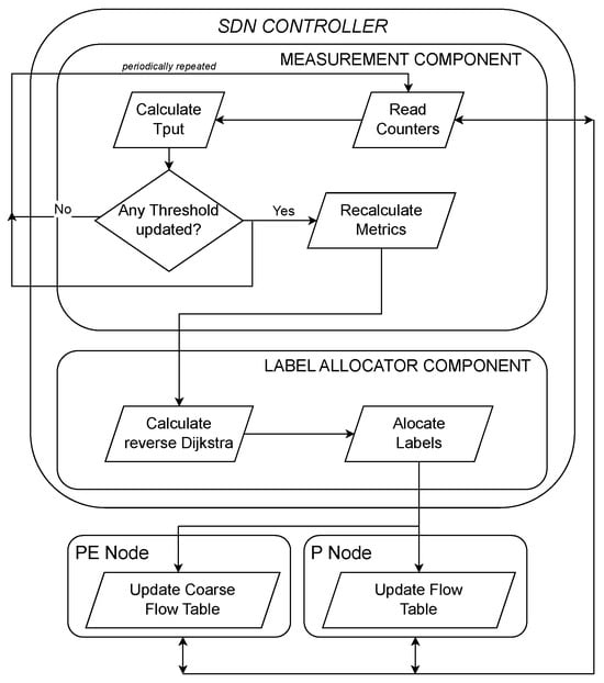
Figure 1.
Flowchart of the proposed mechanism.
The mechanism forwards flows based on MPLS labels. Provider Edge switches (PE) are the source and destination of traffic and at the same time define the boundary of the network using the presented mechanism. Provider switches (P) only mediate in flow forwarding. The labels used are sent by the controller to the switches. The basis of the mechanism is the creation of a relationship between the destination network address and the appropriate label. Labels are global; i.e., all nodes in the network use the same label to deliver traffic to a given end node (PE). Labels are propagated to individual switches according to the tree built by the routing protocol. A new label associated with a given destination node is assigned after recalculation of the reversed Dijkstra algorithm [8], while existing flows are still served by previously assigned labels associated with the same end node. All new flows use the new label, which allows for the stability of already active flows (without changing their routes).
The Measurement Component is responsible for periodically reading the counters on the individual interfaces of the switches. Based on these data, MC calculates the utilization of individual links. If the pre-set utilization threshold is exceeded, the weight of the link in vLSDB is changed. The version of the mechanism described in [8] uses two threshold values (WarnTh and CongTh) and the three corresponding weights (NORM, WARN, CONG), associated with exceeding the individual thresholds. In the previous version of the proposed mechanism, these weights remained constant. However, in this article we introduce a modification in which the weights are not predetermined. Instead, they can vary according to the utilization of the link.
The Label Allocator Component is responsible for constructing and maintaining vLSDB. If even one weight has been changed by MC, then LAC starts recalculation of the paths using the reverse Dijkstra algorithm. Then, a new set of labels is allocated. In each new set, the rule applies that there is one label for each PE node in the entire network.
The flow forwarding and updating mechanisms depend on the type of switch (PE or P). PE nodes employ a flow-based forwarding approach. The definition of flows typically involves a 5-tuple, encompassing source and destination addresses/ports with the Layer 4 protocol.
In accordance with the OpenFlow specification, we propose employing two flow tables within each PE node, namely coarse flow table (CFT) and detailed flow table (DFT). CFT stores mappings between destination networks and pairs (output MPLS label, output interface). DFT captures information on active flows (5-tuple). The match fields for the rules in the DFT vary from those in the CFT.
2.2. Packet Processing Procedure
Upon the arrival of a packet at a PE node, it undergoes processing along a pipeline, presenting two potential scenarios:
- If a packet matches an existing flow in the DFT, it is processed based on the actions specified for that entry. The packet is then tagged with an indicated MPLS label and forwarded to the specified output interface.
- If a packet does not match the DFT, it is redirected to the CFT. This table contains entries with a destination network and associated actions. A predefined MPLS label is pushed, and the packet is directed to a specified output interface. Upon finding a match, the designated actions are executed, and a comprehensive flow entry is generated in the DFT. The action list of the new entry is duplicated from the CFT, and its idle timeout is configured.
It is important to note that, in the second scenario, our mechanism deviates from the OpenFlow specification. In this case, the switch autonomously installs the flow in the DFT, accelerating the flow insertion process and eliminating the need for additional signaling messages to be sent to the controller, such as Packet_IN and Flow_MOD messages.
For the P nodes, a single flow table is sufficient. Upon a packet’s arrival, it is matched on the basis of the label, and then sent to the appropriate output interface with the same label. If a legacy MPLS router serves as a P node, it executes standard label swapping operations. Legacy MPLS routers support static label switched path configuration, enabling the SDN controller to add or remove static MPLS entries via SNMP or NetConf. Therefore, the proposed mechanism can be implemented incrementally within current networks.
2.3. MPLS Label Distribution Procedure
We want to clarify how our mechanism differs from MPLS multipath routing. MPLS makes a selection from predefined (candidate) paths and depending on the constraints selected paths are used. In contrast, our approach dynamically creates new paths between PE nodes on demand, driven by network-wide link utilization monitored by an SDN controller. Our mechanism does not switch between predefined MPLS paths, but always adds new paths that are less utilized in a given moment in time. What is important, the old paths are still used by existing flows, but new flows are transferred via new paths. Old paths remain active until all flows traversing these paths are completed.
Our mechanism does not implement RSVP or LDP label distribution protocols. In our mechanism, only MPLS tagging is important. It does not matter how the MPLS labels are distributed amongst the PE and P nodes. The important assumption for our mechanism is that we use MPLS labels that are global for a particular MPLS domain. Each used label represents a particular PE node. A few paths can connect two PE nodes. In this case, a few MPLS labels represent the same destination node.
The controller assigns constant labels while maintaining a consistent mapping of labels to specific PE nodes. In the case of RSVP or LDP, labels have a local meaning. Due to our mechanism requiring only static label distribution representing PE nodes, segment routing can be applied to distribute these labels in the network. Moreover, each mechanism which can install labels in MPLS routers can be applied.
One of our main objectives is to implement our mechanism with minimal modifications to existing solutions using available devices off-the-shelf. Specifically, the PE nodes need to be modified. P nodes can remain as standard MPLS routers, OpenFlow switches, or switches that only support P node functionality (e.g., Arista devices). When using existing equipment, only static label distribution is required, which can be achieved using protocols such as NetConf or SNMP.
3. Dynamic Weight Modification Procedure
The modification of the mechanism described above is based on a different way of calculating the weights. Our modification generally relates to the triggering procedure of the installation of new flows. The previous version of the proposed mechanism maintained constant weights. This article introduces a modification where the weights are not predefined, they can fluctuate based on the link utilization. In the current version, the weights reflects online link load in the network. Due to this approach, paths are calculated on the basis of the state of the loads in the entire network, not on the overload of only one or a few points in the network. This is a very important modification to the previous version of the mechanism compared to the [8]. This allows for a dynamic view of the whole network represented by constantly changing weights. Calculations are performed only for specific link utilization values.
Due to the fact that the network operates in flow forwarding mode, path recalculations do not cause network instability. The proposed mechanism ensures the stability of the network by leaving existing flows to follow their established paths, thereby preventing any network instability even during path recalculations. Newly calculated paths are reserved for the transmission of new flows. Consequently, the network’s operation in flow forwarding mode ensures a smooth transition and mitigates any potential disruptions caused by path recalculations.
3.1. Weight Modification Scenarios
In this subsection, we present four different triggering procedures for link weight modification. If traffic on at least one link crosses one of utilization thresholds, MC dynamically adjusts the link weights in the vLSDB for all links in the whole network. The proposed mechanisms for determining link weights encompass four distinct scenarios, each tailored to address specific considerations:
- (a)
- Discrete scenario: In this scenario, the weight of the link remains constant within a specified range of link utilization. This approach ensures a straightforward and stable weighting mechanism that responds predictably to variations in link traffic.
- (b)
- Linear scenario: The weight assigned to a link follows a linear function of the current utilization of the link. This scenario introduces a level of proportionality in which the weight of the link is incrementally adjusted in response to changes in transmission throughput. It provides a flexible approach that correlates weight adjustments with the dynamic nature of traffic.
- (c)
- M/M/1 scenario: This scenario involves the recalculation of weights based on the M/M/1 queuing model, a modification proposed in [1].
- (d)
- M/G/1 scenario: Similarly to the M/M/1 scenario, this approach recalculates link weights according to the M/G/1 queuing model. The use of general service–time distributions (G) in this scenario provides a more realistic representation of link performance, extending the simple M/M/1 model.
It is worth mentioning that the values used refer to average delays, which have been somehow ‘translated’ into weight values, i.e., the value of the delay calculated according to the given model corresponds to the value of the assigned weight (the larger the delay, the larger the weight) [10]. The vLSDB database is modified with each reading, but the paths are only recalculated when certain load thresholds are exceeded. We conducted studies assuming that LAC initiates path recalculation only when the link utilization threshold (WarnTh = 50% and CongTh = 80%) is exceeded (up or down) on any link. The thresholds were selected in such a way as to limit the number of recalculations of the path [8].
In the Evaluation section, we will assess and compare the performance of these scenarios, considering their effectiveness in adapting to changes in network conditions. This comparative analysis will show the strengths and weaknesses of each scenario, helping to select an appropriate mechanism based on the specific requirements and characteristics of the network.
3.2. Applicability of the Proposed Scenarios
In this subsection, we briefly discuss the reasons why we choose the listed scenarios. The two simplest link weight modification scenarios are discrete and linear. The discrete scenario for a given range of link utilization returns a constant link weight, while the linear one represents a continuous range of weight values. In the case of the linear scenario, various slopes of the linear function indicate the load increase rate. The choice of these scenarios was dictated by their simplicity, and we believe that it was worth comparing them with more advanced scenarios.
The M/M/1 model is a good description of the situation where packet arrivals are random and service time is relatively unpredictable. The M/M/1 model provides a valuable foundation for understanding basic packet queuing behavior in the network. However, the link weight should reflect the operation of various services and not all of them may behave in accordance with the M/M/1 model.
The M/G/1 model is more flexible as it can handle various service time distributions of packets. It is useful when exponential service times are not a good assumption. This model better describes diverse services, especially when considering flow durations. This is important from the perspective of maintaining individual flows in flow tables. In our case, this issue is relevant to DFT tables.
4. Evaluation of the Mechanism
This chapter describes the simulator used, presents the network topology for which the mechanism was evaluated, proposes performance indicators for the mechanism, and presents the results and their interpretation.
4.1. Simulator Description and Simulation Parameters
To evaluate the mechanism, simulations were performed using the ns-3 simulator [11]. The mechanism required the implementation of new components that implement the functionalities described in [8]. In addition, methods were implemented to select the weights of the links presented Section 2.
Simulations were performed using the US-backbone topology [12]. This network consists of 39 nodes connected by 61 bidirectional links. The network has 10 nodes that act as PE switches (points of attachment of destination networks and traffic sources). Specific nodes (PEs) are chosen to function as connection points for both traffic sources and destinations (Source-Client Network—SCN, and Destination-Client Network—DCN), as illustrated in Figure 2. DCNs and SCNs are networks in which destinations and sources of traffic reside. DCNs and SCNs can be reached via PE nodes. All inter-node links were assigned 100 Mb/s of bandwidth with a delay of 1 ms. The links between the PE and the source and destination nodes were set to 1 Gb/s with a delay of 1 ms. Network traffic was generated using the internal pseudo-random number generator of the ns-3 simulator.
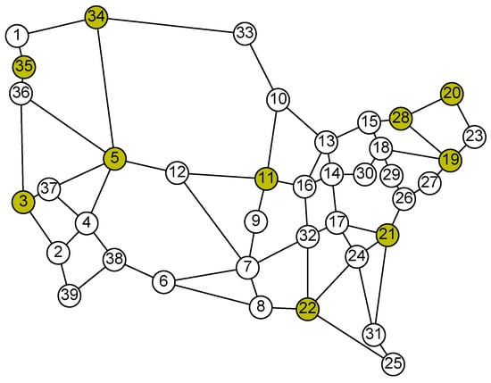
Figure 2.
Topologies used in the numerical evaluation (the green vertices represent SCNs/DCNs) [8].
Experiments with only UDP traffic were performed. The generators were started at the source nodes. For each flow, packet sizes were randomly generated from a normal distribution with a mean of 1350 B and a standard deviation of 150 B. The time between the appearance of individual packets for a single flow was drawn randomly according to an exponential distribution with a mean of 10 ms. The number of packets for each flow was randomly generated from a Pareto distribution with a mean of 150 and a shape coefficient of 1.5. The time between the start of the subsequent flows was drawn according to an exponential distribution with a mean of 1 ms. The traffic parameters were chosen so that the bandwidth of the network was significantly exceeded for the scenario without the proposed mechanism. This approach allows for the evaluation of the gain from implementing multipath transmission for different weight calculation schemes.
For all scenarios, the weights of the links versus the load of the link are shown in Figure 3. All simulations were repeated 20 times. The same values of the parameters of the pseudorandom number generators were used for each test scenario in order to obtain repeatable conditions. Then, the 95% confidence intervals were calculated according to the Student’s t-distribution.
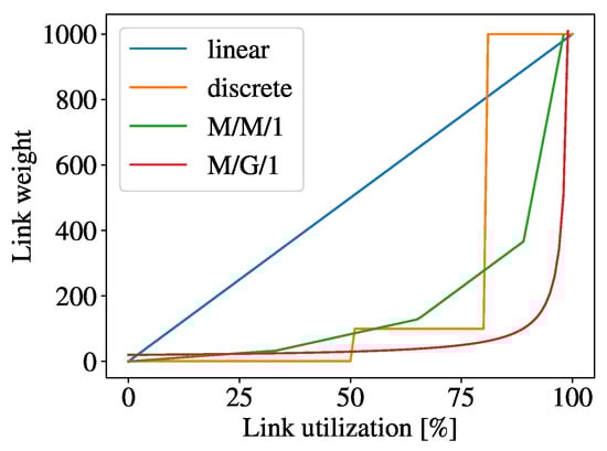
Figure 3.
Proposed scenarios for assigning values to link weights.
4.2. Performance Indicators
To evaluate the proposed methods of link weight modification, the following performance indicators were gathered during the simulations: (i) total number of received data (‘Rx’), (ii) average delay of all flows (‘Avg delay’), and (iii) average throughput achieved for the entire network (‘Avg Tput’). Furthermore, for each scenario, the gain () from using the proposed mechanism was calculated compared to the situation without using multipath transmission. The gain was defined as follows.
where represents the total received data during the simulation using our mechanism, and indicates the total received data when the ‘pure’ OpenFlow scenario is applied. The gain is expressed as a percentage. A positive gain indicates that the proposed mechanism improved the performance of the network.
To assess the scalability of our approach, we measure the total number of flow entries per second in all designated access nodes PE (Figure 4), and the average number of flow entries in an individual core node P per second, as presented in Figure 5. In the context of an OpenFlow considering a P node, the count of flow entries corresponds to the number of labels utilized by that node. For a traditional MPLS node, this count corresponds to the number of MPLS labels stored in the label forwarding information base (LFIB). To demonstrate the effectiveness of our tagging method in flow processing, we monitored the number of label entries across all P switches throughout the entire simulation, recording the maximum values. The average of these maximum values across all simulations is presented in Figure 6.
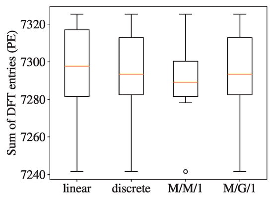
Figure 4.
Comparison of total DFT entries in PE nodes.
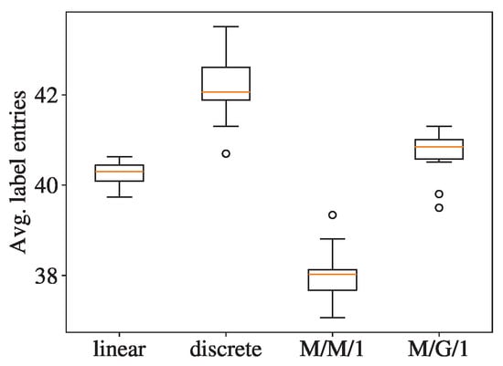
Figure 5.
Comparison of average number of labels in P nodes for selected scenarios.
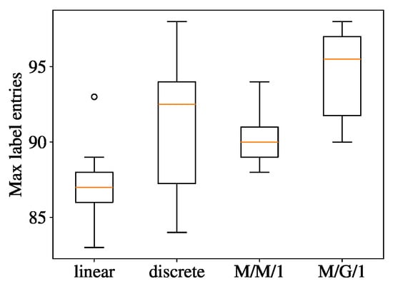
Figure 6.
Comparison of maximum number of labels in P nodes for selected scenarios.
Furthermore, to measure the reduction in the number of entries in the switching tables, we propose the following indicator: the maximum Flow Reduction Indicator () Equation (2). To calculate , it is necessary to distinguish between the entries in the DFT of the PE switches (flows) and the aggregated entries in the P switches (labels). In each second of the simulation, the total number of entries in the DFT was observed in all PE switches. This value is the sum of the number of flows in the network per second. At the same time, the average number of aggregated entries in P switches (labels) was observed in each second. This number is the average number of aggregated flows in the entire network. The highest value of this number (worst case) was used to calculate . The proposed indicator is expressed by Formula (2) and determines the percentage reduction in the number of entries in the switching tables compared to the situation if traditional SDN switching were used. It should be emphasized that is calculated for the scenario in which all flows in each PE node are served by all P nodes.
We introduce one more metric (3), the Comparative Flow Reduction Indicator (). This metric assesses the effectiveness of flow reduction for core nodes when comparing simulated scenarios. In contrast to , utilizes the simulation data collected from both mechanisms being compared. This indicator is defined as follows:
where represents the mean number of flow entries (per second) in a core node P when our mechanism is implemented. Similarly, denotes the mean number of flow entries (per second) in a core node when ‘pure’ OpenFlow is employed for comparison.
4.3. Results
For each of the tested scenarios, 4.66 ± 0.12 GB of UDP traffic data were generated. As can be seen in Table 1, each of the implemented scenarios has a gain compared to the baseline solution (that is, a network without the implemented mechanism).

Table 1.
Simulation results.
In the linear scenario, we observed the maximum amount of data transferred and achieved the highest network throughput. This result can be caused by the unique characteristics of this scenario, where, even under lower loads, the link weights experience the most substantial increase compared to all the other cases under consideration.
For every examined scenario, the average delay (‘Avg delay’) for all flows exhibits a slight increase compared to the baseline (‘pure’ OpenFlow) solution. This phenomenon stems from the nature of the proposed mechanism, which actively seeks out new paths with lower levels of congestion, but these paths are longer. Consequently, the slightly extended transmission delays are a trade-off for the system’s effort to identify less congested routes.
The values obtained for the reduction in the number of entries () for all solutions are at a very similar level (Figure 7). It indicates a very high degree of reduction in the number of flow entries in the network core nodes P compared to the edge nodes PE. This conclusion can also be notified by observing the number of flow entries (Figure 4) in the edge nodes in relation to the average and maximum number of entries in the network core nodes (Figure 5 and Figure 6, respectively).
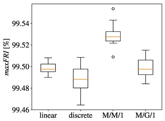
Figure 7.
Comparison of for selected scenarios.
The summarized reductions in flow entries within the core nodes, as defined by Equation (3), for all the considered scenarios are presented in Figure 8. Regardless of the simulated scenario for the link weight scheme, consistently exceeds 94%.
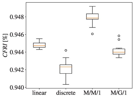
Figure 8.
Comparison of for selected scenarios.
Our mechanism leverages multipath transmission. Specific applications, such as video streaming, may require strict latency limits and minimal data rate constraints. Our simulation results confirm the capability of our approach to successfully meet these criteria. In situations of link congestion, the proposed mechanism seeks out alternative paths for the smooth transmission of data.
The collected results lead to the following conclusions. Our analysis was conducted with the aim of maximizing throughput while minimizing the number of entries in the flow tables. In addition, we examined the impact of selected scenarios on transmission delay. Table 1 shows that the best throughput is achieved using the linear scenario. The highest number of table entries was reached using the M/M/1 scenario. At the same time, this scenario resulted in the fewest table entries in the edge nodes (PE). The discrete scenario achieved the lowest throughput among the proposed scenarios and the highest delay. Despite the large number of flow entries, applying the discrete scenario to our mechanism allows significant flow reduction and aggregation (Figure 7 and Figure 8).
The collected results also show that the choice of the M/G/1 scenario is the best option taking into account all considered metrics. These results confirm the flexibility of the M/G/1 scenario. Using this scenario resulted in the lowest delays, very good throughput (only slightly lower than the throughput achieved with the linear scenario), and good reduction in the number of flow entries. In our opinion, from a practical perspective, the M/G/1 scenario is a versatile choice for operators who want to utilize our mechanism.
In order to find limitations of our proposal, we solved an optimization model. We implemented a multi-commodity max-flow problem [10] that shows the potential capacity of the network. For the simulated topology, the maximum potential throughput was 3400 Mbps. However, this solution assumed that flows do not change over time, network conditions are stable, and flows can be bifurcated. Such conditions cannot be fulfilled in any real network. This value represents static conditions used as input for calculations which are impossible to achieve: traffic fluctuates, demands are changing, sources generate different patterns of traffic, etc. The gap between the optimal value and the results achieved during the simulations demonstrates how much traffic is transferred inefficiently due to fluctuation of flows.
5. Related Work
Several approaches have been proposed to reduce the size of the flow table in the literature. In the work of Curtis et al. [6], a modification of the OpenFlow protocol named DevoFlow is introduced. Similarly to our proposal, this solution allows a switch to autonomously insert certain flow rules into its flow table. The authors categorize flows into two classes, namely mice and elephants, based on measurements. Mice flows can be installed by a switch itself using appropriate wildcards, while elephants require communication with a controller. A switch communicates with the controller to determine the least occupied destination path when an elephant flow is recognized. The flow is then rerouted by installing the necessary flow rules in the switches along the identified path. This approach minimizes communication between the network nodes and the controller. Although the extent of communication can be notable, it depends on the distribution of the elephant flows. Multipath transmission is investigated in [6] to avoid congestion. It is worth noting that DevoFlow’s rerouting of elephant flows may lead to packet reordering during transient states. The authors highlight that the number of reordered packets is negligible compared to the total number of packets in an elephant flow.
In the paper [13], a dynamic flow aggregation approach based on VLAN tagging is proposed. The aggregation procedure is based on the identification of a common path traversed by multiple flows simultaneously. Since the performance evaluation in [13] is carried out on the topologies of rings, trees, and rings of trees, it is challenging to make comparisons with our universal mechanism. They achieve a 48% reduction in flow entries in the network core, compared to our 99% reduction. A notable aspect of their solution is the need for the controller to maintain an extensive database containing information about all active flows, which we consider a potential weakness. When a packet from a new flow reaches a switch, a Packet_IN message is generated regardless of whether an aggregate exists or not. In contrast to our approach, this results in significant communication overhead between the network nodes and the controller.
The challenge in reducing the occupancy of flow tables is also examined in [14]. The authors propose a mechanism that optimizes the flow timeouts of the removal of completed flows. Their approach distinguishes between serving TCP and UDP flows in different manners. For TCP, they assume that the FIN/RST flags signify the end of a flow, leading to immediate eviction of the flow when these flags are observed. The installation of UDP flows is delayed because many of these flows consist of just one or two packets. The authors demonstrate that this proposed procedure can reduce the occupancy of the flow table by up to 62%. The authors do not comment on the signaling overhead associated with information exchange between the switches and the controller. This solution works only in reactive mode. In our view, such a procedure could generate a substantial number of Packet_IN messages. This can result in performance degradation of both the controller and the network.
The authors of [15] propose partitioning a network into regions and advocate using two MPLS tags to reduce the number of entries in the flow tables. This mechanism determines the optimal number of regions resulting in minimization of entries in the flow tables. The authors do not offer any congestion avoidance mechanism. We believe that employing a single node as the entry point to each region increases the probability of congestion. A qualitative comparison with our solution is challenging, as [15] does not apply any multipath transmission techniques. Unlike [15], another benefit of our mechanism lies in the lack of communication required between switches and the controller for each new flow installation.
In the article [16], the authors propose a flow aggregation mechanism. Flow aggregation is achieved by consolidating multiple flows with the same destination but different source addresses into a single entry in the flow table. In this mechanism, both destination network address translation and port address translation are applied. Similarly to our approach, this solution reduces the occupancy of flow tables in the core switches. To compare our mechanism with the one just described, it is necessary to disable multipath transmission in our system. If we used only single-path transmission, we would obtain a constant value of the number of flow entries in core switches, which is less than or equal to the number of PE switches.
The authors of [17] propose a mechanism that facilitates multipath transmission in an SDN network, incorporating routing and path selection algorithms that consider various QoS requirements. The first algorithm, executed by the controller, gathers network state information using the OpenFlow statistics, optimizes network topology, and updates the status of the network. The second algorithm calculates a path and assesses whether it meets the QoS criteria. If the path satisfies delay and bandwidth constraints, it is chosen for transmission and the corresponding flow rules are implemented in the network switches. Otherwise, the subsequent available path is analyzed. In our approach, we do not consider QoS constraints. However, we see potential in proper adjustment of proposed thresholds in order to meet specific flow requirements and use of the CoS field in the MPLS header.
The authors of [18] propose a new scalable rate control architecture, named Scalable Per-Flow Rate Allocation (SPFRA), which can meet the scalability requirements for unicast and multicast flows in SDNs. For unicast flows, the SPFRA selects specific flows within an aggregate flow and limits their rates. The rates of other flows are not controlled, i.e., are allocated by the TCP mechanism. It is important to emphasize that every flow in the aggregation may be classified as uncontrolled or controlled on the basis of the AFSFR algorithm. This approach ensures that QoS requirements related to the bandwidth allocation for controlled and uncontrolled can be fullfield. SPFRA is designed to decrease the number of controlled flows. Unlike our solution, this proposal does not incorporate any form of multipath transmission. It takes into account QoS requirements for specific flow aggregates. In contrast, the application of our proposal leads to the maximization of overall throughput across the entire network.
The prominent industry Traffic Engineering (TE) solution for inter-Data Centre-Wide Area Network (SD-WAN) communication is widely recognized as Google B4 [19]. Google B4 allocates bandwidth and load balances traffic among available tunnels that connect selected sites based on the specific demands of the applications. Google B4 and our mechanism solutions use customized switches. Our solution is designed specifically for communication within a single domain. Considering multidomain communication, our mechanism can be applied with the usage of BGP-LS [20] and a stateful Path Computation Element (PCE) [21,22,23].
Wang et al. [24] propose a mechanism that minimizes the delay of precomputed paths. However, this latency reduction method comes at the expense of an increased number of flow entries in the switches. Our mechanism does not focus on simultaneous delay and bandwidth optimization. The next mechanism described in [25] concentrates on communication between the controller and the switches in order to minimize signaling overhead. A separate pool of tags is used for various paths tagging (one per source-destination pair). This solution lacks a dynamic reaction to congestion, requiring the controller to process each new flow.
In [26], a proposal of the placement of flow rules is presented. This solution aims to accommodate the maximum number of flows while establishing an immediate end-to-end path. The authors of [27] introduce strategies for optimizing the computation of the path. These strategies are specifically designed for 5G-enabled SDN-based transport networks that utilize both wired and wireless components. This mechanism improves QoS. All proposed schemes in [27] incorporate linear integer programming optimization modules to recompute the available paths among OVS switches, the SDN controller, servers and user equipment (UE). The work presented in [28] focuses on addressing elephant flow conflicts mitigation within data centre networks (DCNs). To achieve this goal, the proposed approach introduces a dynamic multipath load balancing algorithm based on Particle Swarm Optimization. The survey by Hamdan et al. [29] provides an overview of existing load balancing techniques and outlines potential future directions within SDNs.
Barakabitze et al. propose in [30] a mechanism that combines Multipath TCP with MPLS Segment Routing in an SDN network. This solution is specifically designed for multimedia streaming that meets QoE requirements in 5G networks. The proposed algorithm searches for multiple paths in the network core that satisfy latency and throughput requirements. Considering the standard architecture of 5G networks, it is uncertain where this mechanism can be located, especially since the client and server may reside in different 5G operator networks. The label stacking proposed by the authors is an effective method of packet transmission along a selected path in the network while minimizing the number of entries in the core nodes. However, this solution requires sending a Packet_IN message to the controller for each new flow. The controller, utilizing the database of possible paths, subdivides the original flow into sub-flows and installs them in the switches. The controller must maintain a vast database of existing sub-flows. This approach incurs significant signaling overhead, which is minimized when using our mechanism (as detailed in [8]). The article lacks numerical values, particularly those showing the number of entries in the ingress switch flow tables. Lack of this information prevents us from making a fair comparison between the mechanism presented in [30] and ours. We would like to highlight that for OpenFlow switches, a critical parameter is the number of entries in flow tables, as emphasized in numerous studies.
The authors of [31] propose a mechanism tailored for SDN Network Virtualization (SDN-NV), enabling tenant controllers to compute paths ensuring bandwidth and multipath transmission. This solution is considered in the context of datacentre transmission. In previous articles on SDN-NV, each tenant maintained its own topology and routing, independent of others, resulting in uncoordinated resource reservation. The solution presented in [31] addresses this challenge by introducing coordination of path creation within virtual topologies, thereby facilitating bandwidth reservation. Comparing this solution with our mechanism is currently impossible, as our mechanism operates within a single topology (non-virtual). However, we recognize the potential for integrating these mechanisms. Our mechanism could be implemented within each virtual topology, treated as a tenant topology, and coordinated by the network hypervisor to establish paths in a multi-tenant environment. In our mechanism, resource reservation is easier thanks to MPLS. Such an extension of our mechanism would require intensive implementation and further performance evaluation.
In [32], a dynamic multipath routing approach is proposed, utilizing reinforcement learning to allocate the path for selected services. In this method, the SDN controller utilizes a machine learning algorithm to dynamically select the routing path that meets the bandwidth, latency, and packet loss requirements. This mechanism was fully implemented and tested in a Mininet environment. However, the evaluation was performed in a very simple topology, and the results primarily focus on machine learning metrics, which are inapplicable in case of our mechanism. We observe that the use of this mechanism results in numerous Packet_IN messages being sent to establish transmission paths.
6. Conclusions
This paper provides a comprehensive comparison of four dynamic link weight allocation methods in the context of a flow aggregation mechanism that employs multipath transmission in a software-defined network. The proposed mechanism uses a centrally controlled MPLS label distribution performed by an SDN controller, eliminating the need for traditional signaling protocols. This innovative approach results in a substantial reduction in both the number of entries and the number of signaling messages within the SDN network.
The simulations carried out in the study reveal that the proposed mechanism significantly enhances network performance, as evidenced by improvements in throughput and resource utilization. In the evaluation, we used four weight assignment scenarios inspired by queuing systems. Notable enhancements were observed when the linear scenario was used. This aggressive approach results in a significant increase of a 58% data transfer within the network compared to the base scenario. The increase in network traffic can be observed due to the effective implementation of multipath transmission.
Furthermore, the proposed mechanism delivers a notable reduction in the number of entries in the switch tables of the core switches. In addition, it uses flow-based traffic measurements to initiate a novel process to compute congestion-free paths for new flows. This approach minimizes signaling overhead and reduces operational costs. The concurrent decrease in flow entries and OpenFlow messages shows the efficient management of traffic within the SDN environment.
Several promising directions for future research and development emerge from the findings presented in this study. More sophisticated algorithms can be considered for dynamic weight adaptation and the potential integration of machine learning or predictive analytics can be explored.
Author Contributions
Conceptualization, G.R. and Z.D.; methodology, G.R. and Z.D.; software, G.R. and Z.D.; validation, G.R. and Z.D.; formal analysis, G.R., Z.D. and P.C.; investigation, G.R. and Z.D.; resources, G.R. and Z.D.; data curation, G.R. and Z.D.; writing—original draft preparation, G.R. and Z.D.; writing—review and editing, G.R. and Z.D.; visualization, G.R.; supervision, P.C and Z.D. All authors have read and agreed to the published version of the manuscript.
Funding
Research project partly supported by the program “Excellence initiative—research university” for the AGH University of Krakow. This work was supported by the Polish Ministry of Science and Higher Education with the subvention funds of the Faculty of Computer Science, Electronics and Telecommunications of AGH University and by the Priority Research Area Digiworld under the program Excellence Initiative-Research University at the Jagiellonian University in Krakow. This research was carried out with the supercomputer ‘Deszno’ purchased thanks to the financial support of the European Regional Development Fund in the framework of the Polish Innovation Economy Operational Program (contract no. POIG. 02.01.00-12-023/08). This research was also supported in part by PL-Grid Infrastructure. Moreover, this research was supported by the National Research Institute, grant number POIR.04.02.00-00-D008/20-01, on “National Laboratory for Advanced 5G Research” (acronym PL–5G) as part of the Measure 4.2 Development of modern research infrastructure of the science sector 2014–2020 financed by the European Regional Development Fund.
Institutional Review Board Statement
Not applicable.
Informed Consent Statement
Not applicable.
Data Availability Statement
Dataset available on request from the authors.
Conflicts of Interest
The authors declare no conflict of interest.
Abbreviations
The following abbreviations are used in this manuscript:
| CFT | Coarse Flow Table |
| CFRI | Comparative Flow Reduction Indicator |
| DCN | Destination-Client Network |
| DFT | Detailed Flow Table |
| LAC | Label Assignment Component |
| LSDB | Link State Database |
| maxFRI | maximum Flow Reduction Indicator |
| MC | Measurement Component |
| MPLS | Multi-Protocol Label Switching |
| PE | Provider Edge |
| P | Provider |
| SCN | Source-Client Network |
| SDN | Software-Defined Network |
| TCAM | Ternary Content Addressable Memory |
| vLSDB | virtual Link State Database |
References
- Fortz, B.; Thorup, M. Optimizing OSPF/IS-IS weights in a changing world. IEEE J. Sel. Areas Commun. 2002, 20, 756–767. [Google Scholar] [CrossRef]
- Domżał, J.; Duliński, Z.; Kantor, M.; Rząsa, J.; Stankiewicz, R.; Wajda, K.; Wójcik, R. A survey on methods to provide multipath transmission in wired packet networks. Comput. Netw. 2015, 77, 18–41. [Google Scholar] [CrossRef]
- Li, M.; Lukyanenko, A.; Ou, Z.; Ylä-Jääski, A.; Tarkoma, S.; Coudron, M.; Secci, S. Multipath Transmission for the Internet: A Survey. IEEE Commun. Surv. Tutor. 2016, 18, 2887–2925. [Google Scholar] [CrossRef]
- Xia, W.; Wen, Y.; Foh, C.H.; Niyato, D.; Xie, H. Survey on Software-Defined Networking. IEEE Commun. Surv. Tutor. 2015, 17, 27–51. [Google Scholar] [CrossRef]
- Chuang, C.C.; Yu, Y.J.; Pang, A.C.; Chen, G.Y. Minimization of TCAM Usage for SDN Scalability in Wireless Data Centers. In Proceedings of the 2016 IEEE Global Communications Conference (GLOBECOM), Washington, DC, USA, 4–8 December 2016; pp. 1–7. [Google Scholar]
- Curtis, A.R.; Mogul, J.C.; Tourrilhes, J.; Yalagandula, P.; Sharma, P.; Banerjee, S. DevoFlow: Scaling Flow Management for High-Performance Networks. ACM SIGCOMM Comput. Commun. Rev. 2011, 41, 254–265. [Google Scholar] [CrossRef]
- Yeganeh, S.H.; Tootoonchian, A.; Ganjali, Y. On scalability of software-defined networking. IEEE Commun. Mag. 2013, 51, 136–141. [Google Scholar] [CrossRef]
- Duliński, Z.; Rzym, G.; Chołda, P. MPLS-based reduction of flow table entries in SDN switches supporting multipath transmission. Comput. Commun. 2020, 151, 365–385. [Google Scholar] [CrossRef]
- The Open Networking Foundation. OpenFlow Switch Specification v1.5.1; The Open Networking Foundation: Palo Alto, CA, USA, 2015. [Google Scholar]
- Pióro, M.; Medhi, D. Routing, Flow, and Capacity Design in Communication and Computer Networks; Morgan Kaufmann Publishers Inc.: San Francisco, CA, USA, 2004. [Google Scholar]
- The ns-3 Consortium. The ns-3 Network Simulator. 2023. Available online: https://www.nsnam.org/ (accessed on 17 June 2024).
- Orlowski, S.; Wessäly, R.; Pióro, M.; Tomaszewski, A. SNDlib 1.0—Survivable Network Design Library. Netw. Optim. 2010, 55, 276–286. [Google Scholar] [CrossRef]
- Mimidis, A.; Caba, C.; Soler, J. Dynamic Aggregation of Traffic Flows in SDN: Applied to Backhaul Networks. In Proceedings of the 2016 IEEE NetSoft Conference and Workshops (NetSoft), Seoul, Republic of Korea, 6–10 June 2016; pp. 136–140. [Google Scholar]
- Shirali-Shahreza, S.; Ganjali, Y. Delayed Installation and Expedited Eviction: An Alternative Approach to Reduce Flow Table Occupancy in SDN Switches. IEEE/ACM Trans. Netw. 2018, 26, 1547–1561. [Google Scholar] [CrossRef]
- Kitsuwan, N.; Ba, S.; Oki, E.; Kurimoto, T.; Urushidani, S. Flows Reduction Scheme Using Two MPLS Tags in Software-Defined Network. IEEE Access 2017, 5, 14626–14637. [Google Scholar] [CrossRef]
- Jia, W.K.; Wang, X. Flow aggregation for large-scale SDNs with scattered address space allocation. J. Netw. Comput. Appl. 2020, 169, 102787. [Google Scholar] [CrossRef]
- Jiawei, W.; Xiuquan, Q.; HuiJuan, L. Dynamic Multipath Routing Mechanism for Multimedia Data Flow Scheduling Over Software Defined Networks. In Proceedings of the 2022 52nd Annual IEEE/IFIP International Conference on Dependable Systems and Networks Workshops (DSN-W), Baltimore, MD, USA, 27–30 June 2022; pp. 191–198. [Google Scholar]
- Kuo, J.J.; Wang, C.H.; Shi, Y.; Yang, D.N.; Chen, W.T. Scalable Rate Allocation for SDN With Diverse Service Requirements. IEEE Trans. Serv. Comput. 2022, 15, 2248–2260. [Google Scholar] [CrossRef]
- Jain, S.; Kumar, A.; Mandal, S.; Ong, J.; Poutievski, L.; Singh, A.; Venkata, S.; Wanderer, J.; Zhou, J.; Zhu, M.; et al. B4: Experience with a Globally-deployed Software Defined WAN. SIGCOMM Comput. Commun. Rev. 2013, 43, 3–14. [Google Scholar] [CrossRef]
- Gredler, H.; Medved, J.; Previdi, S.; Farrel, A.; Ray, S. North-Bound Distribution of Link-State and Traffic Engineering (TE) Information Using BGP; IETF RFC 7752; Internet Engineering Task Force (IETF): Fremont, CA, USA, 2016. [Google Scholar]
- Paolucci, F.; Cugini, F.; Giorgetti, A.; Sambo, N.; Castoldi, P. A Survey on the Path Computation Element (PCE) Architecture. IEEE Commun. Surv. Tutor. 2013, 15, 1819–1841. [Google Scholar] [CrossRef]
- Crabbe, E.; Minei, I.; Medved, J.; Varga, R. Path Computation Element Communication Protocol (PCEP) Extensions for Stateful PCE; IETF RFC 8231; Internet Engineering Task Force (IETF): Fremont, CA, USA, 2017. [Google Scholar]
- Rzym, G.; Wajda, K.; Rzym, K. Analysis of PCE-based path optimization in multi-domain SDN/MPLS/BGP-LS network. In Proceedings of the 2016 18th International Conference on Transparent Optical Networks (ICTON), Trento, Italy, 10–14 July 2016; pp. 1–5. [Google Scholar]
- Wang, Y.C.; Lin, Y.D.; Chang, G.Y. SDN-based Dynamic Multipath Forwarding for Inter-data Center Networking. In Proceedings of the 2017 IEEE International Symposium on Local and Metropolitan Area Networks LANMAN, Osaka, Japan, 12–14 June 2017; pp. 1–3. [Google Scholar]
- Lin, W.; Niu, Y.; Zhang, X.; Wei, L.; Zhang, C. Using Path Label Routing in Wide Area Software-Defined Networks with OpenFlow. In Proceedings of the 2016 International Conference on Networking and Network Applications NaNA, Hakodate City, Japan, 23–25 July 2016; pp. 149–154. [Google Scholar]
- Bera, S.; Misra, S.; Jamalipour, A. FlowStat: Adaptive Flow-Rule Placement for Per-Flow Statistics in SDN. IEEE J. Sel. Areas Commun. 2019, 37, 530–539. [Google Scholar] [CrossRef]
- Bagaa, M.; Dutra, D.L.C.; Taleb, T.; Samdanis, K. On SDN-Driven Network Optimization and QoS Aware Routing Using Multiple Paths. IEEE Trans. Wirel. Commun. 2020, 19, 4700–4714. [Google Scholar] [CrossRef]
- Shu, Y.; Gao, D. A Dynamic Multipath Load Balancing Algorithm Based on Particle Swarm Optimization in DCN. In Proceedings of the 2023 IEEE 14th International Conference on Software Engineering and Service Science (ICSESS), Beijing, China, 17–18 October 2023; pp. 126–130. [Google Scholar]
- Hamdan, M.; Hassan, E.; Abdelaziz, A.; Elhigazi, A.; Mohammed, B.; Khan, S.; Vasilakos, A.V.; Marsono, M. A comprehensive survey of load balancing techniques in software-defined network. J. Netw. Comput. Appl. 2021, 174, 102856. [Google Scholar] [CrossRef]
- Barakabitze, A.A.; Sun, L.; Mkwawa, I.H.; Ifeachor, E. A Novel QoE-Centric SDN-Based Multipath Routing Approach for Multimedia Services over 5G Networks. In Proceedings of the 2018 IEEE International Conference on Communications (ICC), Kansas City, MO, USA, 20–24 May 2018; pp. 1–7. [Google Scholar]
- Yoo, Y.; Yang, G.; Lee, J.; Shin, C.; Kim, H.; Yoo, C. TeaVisor: Network Hypervisor for Bandwidth Isolation in SDN-NV. IEEE Trans. Cloud Comput. 2023, 11, 2739–2755. [Google Scholar] [CrossRef]
- Chiu, K.C.; Liu, C.C.; Chou, L.D.; Lv, J. Reinforcement Learning-Based Service-Oriented Dynamic Multipath Routing in SDN. Wirel. Commun. Mob. Comput. 2022, 2022, 1330993. [Google Scholar] [CrossRef]
Disclaimer/Publisher’s Note: The statements, opinions and data contained in all publications are solely those of the individual author(s) and contributor(s) and not of MDPI and/or the editor(s). MDPI and/or the editor(s) disclaim responsibility for any injury to people or property resulting from any ideas, methods, instructions or products referred to in the content. |
© 2024 by the authors. Licensee MDPI, Basel, Switzerland. This article is an open access article distributed under the terms and conditions of the Creative Commons Attribution (CC BY) license (https://creativecommons.org/licenses/by/4.0/).