Featured Application
Novel design of functionally graded graphene nanocomposite structures.
Abstract
This study is concerned with the nonlinear free vibration of a cracked functionally graded porous cylindrical panel reinforced with graphene platelets by introducing a phase-field crack model. Conventional crack modeling by separating the grid nodes lying on the crack line is not only painstaking but also suffers from numerical instability. To overcome this problem, the internal crack is modeled by adopting the phase-field formulation and a virtual geometry rotation. The nonlinear numerical method is developed based on the first-order shear deformation theory incorporated with the von Kármán geometry nonlinearity in the framework of the 2-D extended natural element method, a recently introduced mesh-free method. The crack-induced singular field is represented by adopting the crack-tip singular functions, and the troublesome numerical locking is restrained by combining the MITC3+ shell concept and the shear stabilization factor. The curved shell surface is mapped to a 2-D rectangular NEM grid to avoid difficulty in defining the interpolation functions. The developed numerical method is verified through a comparison with the reference solutions, and the large-amplitude free vibration of porous cracked functionally graded grapheme platelet-reinforced cylindrical panels is profoundly examined by changing the major parameters.
1. Introduction
Currently, nanocomposites in which nanofillers such as graphene platelets (GPLs) or carbon nanotubes (CNTs) are reinforced have been attracting much attention [1,2]. These nanofillers exhibit excellent physical, chemical, and electrical properties so that their introduction can dramatically improve the performances of conventional composites. It was reported that the structural strength of polymeric composites is greatly increased when only a tiny amount of nanofillers are reinforced [3]. In terms of application, the nanocomposites are manufactured in the form of beams, plates, and shells, and their basic mechanical behaviors such as static deflection, free vibration, and buckling have been intensively and continuously investigated [4,5,6]. This is because the quantitative investigation of their mechanical responses is needed for their practical design in the specific configuration under consideration, even though the superiority of material grapheme has been qualitatively well-known. The mechanical behaviors of these nanocomposites are strongly affected by the distribution patterns of nanofillers, particularly through the thickness of the composite structures. So, several purposeful thickness-wise distribution patterns have been proposed according to the notion of functionally graded material (FGM), which was introduced in the late 1990s to overcome bi-material-type heat-proof composites [7,8,9,10]. The representative functional distributions are FG-U, FG-O, FG-X, and FG-∧, and the nanocomposite structures with these functional distributions of nanofillers are called FG-GPLRC and FG-CNTRC structures.
Besides the functional distribution of nanofillers, the mechanical behaviors of functional nanocomposite structures are affected by the porosity distribution. This is because the difference in the solidification temperatures of a matrix and a filler during fabrication produces porosities [11,12], and both the stiffness and mass of composite structure are remarkably influenced by the amount and distribution pattern of porosity. In this context, recently, porosity has been widely taken into consideration in the parametric investigation of the mechanical behaviors of functional nanocomposites with respect to the porosity coefficient and distribution [13,14,15]. Moreover, the combination of nanofiller and porosity distribution patterns leads to more diverse mechanical behaviors of functional nanocomposites because both distribution patterns are usually not the same as one another. Due to their excellent material properties and the low density, functionally graded porous nanocomposites have been attracting much attention for high-strength, lightweight structures [16].
Carbon nanotubes are cylindrical in form so their production costs are relatively higher than that of graphene platelets. In addition, their material properties are not isotropic but orthotropic, with a higher elastic modulus in the direction of CNT alignment. Thus, the mechanical responses of FG-CNTRC structures are sensitive to the CNT alignment direction such that those in the two off-alignment directions are worse than those of FG-GPLRC structures [17,18,19]. On the other hand, FG-GPLRC structures are usually modeled as isotropic materials according to the micromechanical homogenization approach [20]. For this reason, together with their relatively low production costs, FG-GPLRC structures nowadays are attracting more attention [18]. Meanwhile, the studies on FG-GPLRC have been based on those of FG-CNTRC because GPLs received attention somewhat later than CNTs. As well, studies on the fundamental mechanical responses of FG-GPLRC structures have mostly included geometry nonlinearity in the displacement field according to the increase in interest on large deflection bending and large amplitude vibration.
Regarding studies on the nonlinear free vibration of GPL-reinforced structures, Feng et al. [21] studied the nonlinear free vibration of a multi-layer polymer composite beam reinforced with non-uniformly distributed GPLs through the thickness by applying Hamilton’s principle and the von Kármán nonlinearity to Timoshenko beam theory. Zhang et al. [22] numerically examined the nonlinear vibration of graphene sheets by applying the element-free kp-Ritz method to the nonlocal elasticity theory, which accounts for the size effect. Gao et al. [23] numerically examined the influence of GPL and porosity distributions on the nonlinear natural vibration of FG-GPLRC porous plates supported by the elastic foundations by applying the differential quadrature method (DQM). Shen et al. [24] investigated the temperature-dependent large amplitude vibration of GPLRC-laminated cylindrical panels resting on an elastic foundation using a two-step perturbation technique. Kiani [25] proposed a nonlinear formulation for the nonlinear natural vibration of GPLRC-laminated plates using a non-uniform rational B-spline (NURBS)-based isogeometric finite element method. Teng and Wang [26] analytically investigated the influence of porosity coefficient and the foam skeleton distribution on the nonlinear free vibration of graphene-reinforced plates by applying Hamilton’s principle to the von Kármán nonlinear plate theory. Song et al. [27] numerically and parametrically investigated the temperature-dependent nonlinear free vibration characteristics of the cracked FG-GPLRC beams resting on an elastic foundation using the DQM. Tao and Dai [28] analyzed the size-dependent nonlinear free vibration of FG-GPLRC annular sector microplates by applying the isogeometric analysis to a four-variable higher-order SDT. Javani et al. [29] investigated the nonlinear natural vibration of an FG-GPLRC circular plate on the nonlinear elastic foundation using the generalized DQM. Wang and Chen [30] numerically investigated the nonlinear natural vibration of an FG-GPLRC titanium alloy trapezoid plate using the Rayleigh–Ritz method and the direct iterative process.
As can be found from the literature survey, previous studies on the nonlinear free vibration of FG-GLRC structures were mostly limited to beams and plates and furthermore assumed that the structures are perfect without any cracks. However, the structural elements used in real applications have various forms such as cylindrical and conical shells, and various abnormal loading conditions such as thermal shock may induce micro-cracking [31] within GPL-reinforced nanocomposite structures. These undesired cracks damage the surrounding region such that the whole structural strength becomes significantly weakened, implying that the consideration of a crack is essential in structural analyses and designs. Meanwhile, the consideration of a crack in a mesh- or grid-based numerical analysis may frequently suffer from the painstaking crack modeling job [32,33,34]. Furthermore, the crack modeling deteriorates the mesh uniformity, which may induce numerical instability and even numerical failure.
In this situation, this study aims to determine the large amplitude natural vibration of a porous FG-GPLRC cylindrical panel with a central inclined crack. To avoid the above-mentioned problems in crack meshing, the phase field formulation (PFF) [35,36] is adopted and a virtual geometry rotation is introduced into the framework of 2-D extended NEM [19,37]. In other words, the nodes sitting on the crack lines are not separated and the region at the crack-tip in the grid is not centrally refined. Instead, the crack line is represented by the phase field and its virtual rotation to the NEM grid line, and the crack-induced singularity is enhanced by the near-tip singular functions [38]. The large displacement field is expressed by the first-order SDT incorporated with the von Kármán geometry nonlinearity. The painstaking definition and manipulation of high-smooth Laplace interpolation (L/I) functions in NEM is relaxed by mapping the cylindrical neutral surface to a rectangular plane. And, the troublesome numerical locking [39,40] is restrained by adopting the MITC3+ shell concept and the shear stabilization factor. In the MITC3+ shell concept, the transverse shear strains are re-interpolated at six tying points within a three-node triangular shell element to suppress shear locking [41]. The developed nonlinear vibration method is justified through the comparison with the reference solutions. And, the nonlinear natural vibration characteristics of porous FG-GPLRC cylindrical panels are profoundly investigated by changing the major parameters of GPLs and porosity and by combining the GPL and porosity distributions. Furthermore, a comparison with FG-CNTRC cylindrical panels is also presented.
2. Functionally Graded Porous GPLRC Cylindrical Panel
Figure 1a represents a cylindrical panel in which GPLs are distributed with a specific distribution pattern through the thickness. Cartesian coordinates are introduced on the corner of the neutral surface of the panel with the -axis along the cylinder axis and the -axis through the thickness. The radial distance between the neutral surface and the mid-surface is denoted by [42]. The geometry of cylindrical panel is characterized by length , radius , sub-tended angle , and uniform thickness . Then, the material domain can be expressed by . Four thickness-wise functional distribution patterns of GPLs are depicted in Figure 1b—FG-U, FG-O, FG-X, and FG-Λ—where the GPLs are uniform in FG-U, biased towards the neutral surface in FG-O, concentrated in the top and bottom regions in FG-X, and biased towards the bottom in FG-Λ. In addition, pores and a central crack are included within the panel, as will be described below.
The thickness-wise volume fractions of the GPLs and the underlying matrix are denoted by and . Then, either one is enough to identify both volume fractions as two volume fractions satisfy the physical constraint given by
The GPL volume fraction is chosen in this study and its mathematical expression becomes
depending on the GPL distribution pattern, where the total GPL volume fraction is calculated by
using the GPL mass fraction , and the two densities and of the GPL and matrix material.
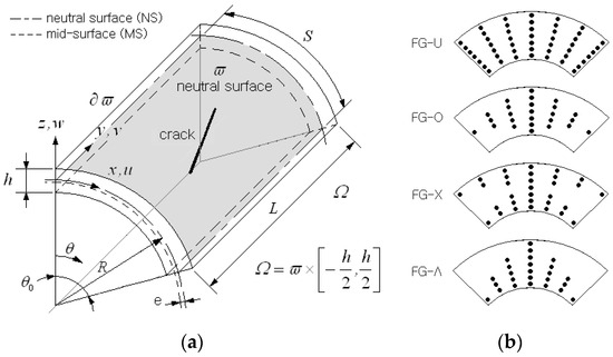
Figure 1.
A cylindrical panel reinforced with graphene platelets: (a) geometry and dimensions, and (b) GPL distribution patterns.
GPLs are modeled as a rectangular solid with length , width , and thickness , and their distribution is assumed to be uniform within the underlying matrix in the local sense. So, the graphene-reinforced composites are usually considered isotropic and their effective Young’s modulus is evaluated using the Halphin-Tsai approach [20]:
with
in which and are the elastic moduli of GPLs and matrix material, and the relative geometry ratios and are defined by
In a similar manner, the effective values of mass density and Poisson’s ratio of GPLRC are determined by
using the simplest linear rule of mixture.
The porosity within GPLRC is generally characterized by size, shape, orientation, and dispersion structure of pores. In this study, the former three factors are assumed to be uniform in space, but only the relative volume of pore and the dispersion structure are considered for the parametric investigation of pores. Figure 2 shows three different porosity distributions considered in this study, center-biased (PD_1), outer-biased (PD_2), and uniform (PD_3), which are expressed as
where denotes the porosity coefficient, which is related to the relative volumes of pores within GPLRC.

Figure 2.
Three porosity distributions (PD_1: center-biased, PD_2: outer-biased, and PD_3: uniform).
The porosity affects the effective material properties of GPLRC so that the above elastic modulus , shear modulus , and mass density should be corrected. Denoting the effective material properties before and after modification by and , the modification is made through
except for the mass density. For the effective mass density, the porosity coefficient should be corrected using the relationship given by
between the mass density and elastic property [43]. Then, the corrected porosity coefficient for the mass density is determined by
for porosity distribution PD_1, for example.
Figure 3 represents a central crack within a cylindrical panel, which is characterized by the inclination angle and the length . The crack center coincides with the center of the cylindrical panel, and these two parameters are taken as variables for the parametric experiment. The polar coordinates are added to two crack tips in order to express the singular functions the are needed to capture the singularity at the crack tips. The existence of a crack can be determined by either creating a crack line or employing the phase field concept [35] without creating a crack line. The former is usually implemented by separating the nodes sitting on the crack line in FEM or NEM grids [2]. But, the node separation in the former approach not only is painstaking but also produces a non-uniform distorted grid, which may deteriorate the numerical accuracy or even lead to numerical failure. This difficulty becomes more severe in the crack propagation simulation for which tedious crack tracking is essential [35].
On the other hand, the latter approach employs an additional state variable called phase field (). The value of indicates the damage state at point within the structure such that indicates fully damaged while denotes completely undamaged. This method does not need the painstaking crack mesh generation, which can significantly reduce the troublesome mesh adaptation job in crack propagation simulation to track the crack. In addition, there is no need to assume material homogeneity and isotropy regions away from the crack. Thus, there exist no limitations in the material type for the phase field formulation. But, it needs an extra approximation of the phase field to represent the existence of a crack within the material domain. The crack line is modeled by connecting the points with , and the transition region [35] between the fully damage crack line and the completely undamaged region has the value of . The size of the transient region is denoted by the length scale [44,45], which is controlled by the grid density near the crack line when the phase field is approximated using the same grid constructed for the displacement field approximation.
According to this concept, the total strain energy and the total kinetic energy of cracked structure are expressed as
where and denote the total strain and total kinetic energies when the structure is completely undamaged.
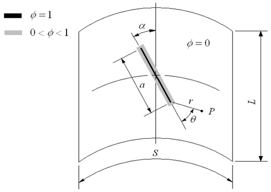
Figure 3.
A central crack and phase field within a cylindrical panel.
Letting be the displacement vector, the displacement field of FG-GPLRC cylindrical panel is expressed as
according to the FSDT. The large defection of a cylindrical panel is represented by the von Kármán nonlinearity, which leads to the strain-displacement relations given by
with , , and , where , and denote the and partial derivative matrices defined by
with and . Here, and are the deflection derivatives of a panel, which are assumed to be known a priori, as described later. Then, the strain–stress constitutive relations become
with and .
3. NE Approximation of Nonlinear Natural Vibration Using Phase-Field Crack Model
Referring to Figure 4, the panel neutral surface is uniformly divided into a finite number of three-node Delaunay triangles. As mentioned above, the crack line is modeled using the phase field and the crack-induced singular field is represented by adding the crack-tip singular functions without refining the local NEM grid in the vicinity of crack tip. Thus, in an extended NEM, the displacement is approximated as
using the L/I functions [46,47] and the crack-tip singular functions and [38].
The singular functions are defined using two distinct crack-tip polar coordinates , as depicted in Figure 3. Here, are the non-singular nodal displacement vectors at node within the NEM grid generated with nodes and Delaunay triangles. And, indicates the singular vector corresponding to the k-th singular function.
The derivation and manipulation of L/I functions on the curved cylindrical surfaces are troublesome, so the physical NEM grid on the panel neutral surface is transformed into 2-D rectangular NEM grid for the computation. Then, according to the geometry transformation and the chain rule summarized in Appendix A, the enriched NE approximation of the bending-membrane strain in Equation (18) and the transverse shear (T/S) strain in Equation (19) ends up with
with . Here, is computed on the 2-D rectangular NEM grid while is computed directly on the panel neutral surface (Similarly for and ).
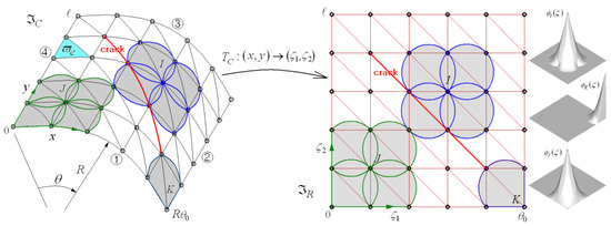
Figure 4.
A geometry transformation between the curved and planar NEM grids and L/I functions defined on a 2-D rectangular plane.
Note that the first term on the right-hand side in Equation (29), which is approximated with -L/I functions , may suffer from numerical locking when the deformation is bending-dominated [39,40]. This problem can be effectively suppressed by indirectly interpolating this non-singular term of T/S strain according to the MITC3+ shell approach [41], as addressed in Appendix B. The analytical calculation of Equations (A5) and (A6) in Appendix B using Equations (19) and (22), together with the chain rule between two coordinates and in Figure 4, results in
Here, is the triangle-wise matrices in function of , and , and are the non-singular triangle-wise nodal vectors.
Next, the nonlinear vibration of the FG-GPLRC cylindrical panel is governed by the dynamic form of the energy principle given by
In accordance with the phase field concept, the virtual strain energy and the virtual kinetic energy of cracked cylindrical panel are defined by
where denotes the radial distance of the neutral surface from the panel mid-surface and is a symmetric matrix given by
with and the identity matrix .
Figure 5 represents a NEM grid composed of Delaunay triangles and grid points, which will be described later in detail. In the present study, the phase field introduced in Figure 4 is approximated using L/I functions defined on the NEM grid. So, the crack line in red may not have lied on the vertical, inclined, or horizontal lines within the NEM grid, as depicted in Figure 5. In such a situation, an additional numerical technique is needed to effectively approximate the phase field. In this study, the crack coordinates including the crack line transforms the virtual phase field coordinates such that the crack line lies on the inclined line within the NEM grid.
with .
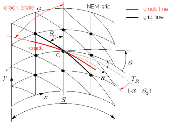
Figure 5.
Rotation of inclined central crack for the phase field approximation in NEM.
Next, substituting Equations (32) and (33) into Equation (31) through the constitutive relations (23) and (24), under the assumption harmonic motion , one obtains the nonlinear modal equation given by
where and denote the nonlinear natural frequencies and natural modes, and two linear and one nonlinear stiffness matrix and the mass matrix are calculated as
where , and with and . Meanwhile, is the modified shear modulus matrix defined by
with the largest side length of the Delaunay triangle. And, is a shear stabilization parameter, which was determined through a preliminary experiment, as addressed in the next section.
The nonlinear modal Equation (37) was solved using the three-step direct iterative method [48]. At step 1, the linear natural frequencies and natural modes were computed by excluding from Equation (37). At step 2, the computed target natural mode Was scaled up using the desired amplitude–thickness ratio , and then, the values of and in Equations (18) and (19) were calculated and the nonlinear stiffness matrix Was constructed. At step 3, the nonlinear natural frequencies and natural modes were computed. Steps 2 and 3 were repeated until the relative difference between the nonlinear natural frequencies computed at two consecutive iterations was less than 0.1%.
4. Numerical Results
The nonlinear free vibration formulae given in Section 3 for cracked porous cylindrical panels using the phase field theory and the crack rotation concept were coded in the framework of 2-D XNEM [19]. All the stiffness and mass matrices given in Equations (38)–(41) were numerically integrated using 7 Gauss integration points. First, the sensitivity of the present method to the density of 2-D NEM grid was investigated using a clamped intact (i.e., without an internal crack) aluminum cylindrical panel with the geometry dimensions of . In this study, two kinds of boundary conditions, simply supported (S) and clamped (C), were used, and which were implemented as
at or . The component in Equation (44) was excluded when the clamped condition was specified for the side with or . The isotropic material properties were and , and the first natural frequency was calibrated as with the flexural rigidity . The non-dimensional first frequencies were computed and are presented in Table 1, where indicates the relative percentage difference with respect to the fundamental frequency computed with a grid density of . It was found that the relative difference uniformly decreases in proportion to the grid density such that it becomes less than 3.0% when the grid density goes up to . So, according to this convergence result, the grid density was set to for the whole numerical experiment in this paper.

Table 1.
Dependence of non-dimensional first frequency of an isotropic intact cylindrical panel on the grid density ( CCCC).
Next, the accuracy of the present method was verified by comparing it with the phase field formulation of Torabi and Ansari [36]. A metal–ceramic functionally graded cylindrical panel with an internal crack, shown in Figure 3, is taken. The geometric dimensions and the boundary condition are the same as those from the above convergence test problem, and also, the previous aluminum is taken for the metal while alumina with and is chosen for the ceramic. The power-law function of is adopted to identify the thickness-wise volume fractions of the ceramic and also the metal using the relation . The relative crack length is set at 0.3, while the crack angle and the ceramic power-law index are taken as variables. By comparing with the reference solutions, the shear stabilization factor in Equation (42) was set at to reflect the influence of crack angle on the stiffness matrix in Equation (38). The phase field in the mass matrix in Equation (41) was set to 0 in order to prevent the over-reduction of mass due to an internal crack in the coarse NEM grid. The comparison in Table 2 reveals that the present results show good agreement with the reference solutions, with the maximum relative difference equal to 4.838%. Except for the case of , all the present results lead to the relative differences being less than 1.0%. Meanwhile, the fundamental frequency uniformly decreases proportional to the ceramic power-law index because the relative region occupied by a stiffer ceramic reduces in proportion to the value of . It is found that the first frequency uniformly increases with increasing crack inclination angle because the reduction in the circumferential stiffness of a panel shows that the circumferentially dominated free vibration becomes smaller as the crack inclination angle increases.
Table 2.
Comparison of first frequencies of ceramic–metal FG cracked cylindrical panels ( , CCCC).
Figure 6a,b comparatively represent the effect of crack inclination angle on the second natural modes for and 0.6, respectively, when the ceramic power-law index is 0. The reason for showing the second mode is because the fundamental mode does not produce any apparent change with respect to the crack angle. It is seen that the mode shape becomes separated from the left and right as goes to zero, while it becomes similar to the non-separated single plate vibration mode as increases.

Figure 6.
Variation in the second-mode shapes of a clamped FG-GPLRC cylindrical panel to the crack inclination angle ( and ) for (a) at and (b) at .
The present method is also verified through two nonlinear free vibration analyses. One is an isotropic intact cylindrical panel under the simply-supported boundary condition with the geometry and material data given by , and . The nonlinear-to-linear frequencies were computed for six different values of amplitude–thickness ratio , and the frequency–amplitude plot is compared in Figure 7a. The reference solution by Shin [49] was solved by applying the fourth-order Runge–Kutta method to the FSDT. Meanwhile, the other reference solution by Shen and Xiang [50] was analytically solved by applying a two-step perturbation method to the HSDT. The von Kármán-type geometric nonlinearity was adopted to both solutions, as for the present study. One can clearly see that the three methods are in excellent agreement such that the maximum relative difference in between the present method and that of Shin [49] is 1.149% at .

Figure 7.
Comparison of frequency–amplitude curves of isotropic cylindrical panels: (a) non-porous; (b) porous (PD 1) [49,50].
The other nonlinear example is an intact porous isotropic cylindrical panel with the geometric and material data given by , , and . The porosity distribution is PD_1 shown in Figure 2 with the porosity coefficient , and the four sides of panel are clamped. The computed frequency–amplitude plot is compared with those of Keleshteri and Jelovica [51] in Figure 7b, where two reference solutions were numerically obtained by applying the generalized DQM to FSDT and HSDT. The comparison reveals that the plot of the present method is positioned between HSDT and FSDT, but it is closer to FSDT because the present method is based on FSDT.
Next, the sensitivity of the present phase-field crack model to the grid density was examined using the isotropic cylindrical panel taken from Table 1 in which an inclined central crack is included. The relative length and the inclination angle of a crack were chosen as 0.7 and °. The non-dimensional first frequency and its linear-nonlinear ratio at were computed for five grid densities and recorded in Table 3. It is clearly observed that the relative difference of uniformly decreases proportional to the grid density. Also, the relative fluctuation in becomes smaller in proportion to the grid density.
Table 3.
Sensitivity of and of a cracked isotropic cylindrical panel to the grid density ( °, CCCC).
The present method was also applied to non-porous FG-GPLRC cylindrical panels with a central crack to examine the influence of crack angle and length, and GPL distribution pattern on the fundamental frequency. The geometric dimensions and the aluminum material properties are the same as those of the first example given in Table 1, where the first frequencies are calibrated as . Meanwhile, the geometric dimensions and the material properties of GPLs are as follows: , and , respectively. It is observed from Table 4 that the non-dimensional fundamental frequency decreases proportionally to the crack length because the panel stiffness decreases as the crack length increases. Meanwhile, regarding the GPL distribution pattern, FG-X leads to the highest level while FG-O shows the lowest level. This relative order among the GPL distribution patterns is attributed to the fact that the panel stiffness becomes higher as GPLs become biased towards the top and bottom of the panel; see Figure 1b.
Table 4.
Non-dimensional first frequencies of non-porous FG-GPLRC cylindrical panels with a central crack ( , CCCC).
Next, the nonlinear natural vibration of the clamped FG-GPLRC cylindrical panel with a central crack was profoundly examined by changing the major parameters. Figure 8a represents the effect of crack inclination angle on the variation in nonlinear-to-linear frequency ratio to the amplitude–thickness ratio . The mass fraction and distribution pattern of GPLs are 0.4% and FG-U, and the relative crack length is set at 0.3. It is seen that the frequency ratio becomes uniformly smaller in proportion to the crack inclination angle, but the decrease trend becomes smaller proportional to the crack angle. Thus, this trend reveals that the nonlinearity in free vibration decreases with increasing crack inclination angle. Figure 8b represents the effect of crack relative length on the nonlinear natural vibration of the FG-U GPLRC cylindrical panel when the crack inclination angle is zero. It is seen that the frequency ratio becomes slightly smaller with increasing crack relative length because the panel stiffness drops proportional to the crack relative length.
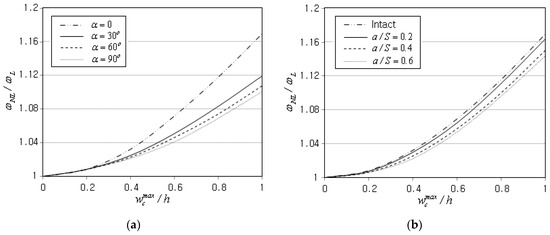
Figure 8.
Variation in nonlinear-to-linear frequency ratio (FG-U, ) (a) to the crack angle and (b) to the crack relative length (°).
Figure 9a represents the variation in frequency ratio to the GPL mass fraction for the FG-O GPLRC cylindrical panel with a central crack. The inclination angle and relative length of a crack are set at and 0.3. Each nonlinear free vibration analysis for five values of was completed within five minutes on an Intel Pentium PC with a dual core CPU (1.86 GHz). It is observed that the frequency ratio uniformly increases in proportion to the GPL mass fraction because the mass fraction increase in GPLs with a higher elastic modulus leads to an increase in panel stiffness. Figure 9b represents the influence of the GPL distribution pattern on the frequency ratio , for which the GPL mass was set to 0.4%, while three different GPL distribution patterns were additionally considered. It is found that the magnitude order of frequency ratio is FG-X, FG-O, FG-U, and FG-Λ. This trend is slightly different from the magnitude order of linear fundamental frequency given in Table 3, where FG-O shows the lowest level. In the frequency ratio , FG-O shows the second highest level, which is caused by the fact that the magnitude of is not determined by the magnitudes of and but the relative value of these two. This trend was also observed from Figure 8a, where larger inclination crack angles showed lower frequency ratios even though the linear fundamental frequency was higher at larger inclination crack angles.
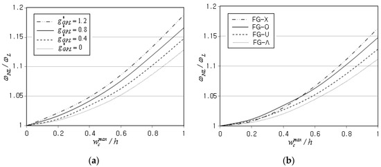
Figure 9.
Variation in nonlinear-to-linear frequency ratio (, °) (a) to the GPL mass fraction (FG-O) and (b) to the GPL distribution pattern ().
Next, the nonlinear free vibration of the cracked cylindrical panel between GPLRC and CNTRC was compared by keeping the material properties of the matrix unchanged. The (10,10) single-walled CNTs [52] were taken, and their orthotropic material properties are presented in Table 5. The effective material properties of the CNTRC structures are evaluated as
according to the modified linear rule of mixtures (MLRMs), where the CNT efficiency parameters are dependent of the CNT total volume fraction [53]. Note that LRM accounts only for matrix-fiber deformation but does not consider nonlinearities such as fiber–matrix adhesion that might consume a large chuck of applied energy.
Table 5.
Material properties of (10,10) single-walled CNTs ().
Figure 10a represents the variation in to the relative central amplitude of a cracked FG-X cylindrical panel with and °, where the angle ° denotes that CNTs are aligned in the direction of cylinder axis. The frequency ratio shows a noticeable change to the CNT volume fraction , even though the extent of increase is not so large when compared with that shown in Figure 9a. Figure 10b represents the variation for different GPL volume fractions , where the ratio and its dependence on are shown to be smaller than those shown in Figure 10a. Note, from the relation in Equation (3), that equals 10.75% of the GPL mass fraction. Therefore, it is found that the dependence of frequency ratio on and becomes insensitive in proportion to the amount of GPLs and CNTs, and this trend is more apparent at CNTRC for the same volume fraction. This is because the nonlinearity intensity becomes saturated as the structural stiffness reaches the critical value owing to the increase in CNTs and GPLs, as will be seen later.

Figure 10.
Comparison of nonlinear-to-linear frequency ratios between GPLRC and CNTRC (FG-X, , °): (a) CNTRC; (b) GPLRC.
Before the examination of the effect of higher and on the variation in , the fundamental frequencies of GPLRC and CNTRC are compared for the FG-X cylindrical panel with and °. From Table 6, it is found that the first frequencies of GPLRC are much higher than those of CNTRC, implying that GPLRC possesses much higher structural stiffness than CNTRC for the same volume fraction. This is because the material properties of CNTRC are axis-dependent such that the two lateral elastic moduli are much lower than the axial one. It is clearly found that the non-dimensional first frequency of CNTRC becomes higher when the CNTs are aligned in the circumferential direction (i.e., ).
Table 6.
The non-dimensional linear first frequencies (FG-X, , °).
Figure 11a represents the variation in with respect to the GPL mass fraction for different GPL distribution patterns when is 1.0. It is seen that the frequency ratio becomes saturated such that FG-O and FG-Λ approach the upper bounded value while FG-U and FG-X approach the lower bounded value. Thus, it has been justified that the nonlinearity intensity in the free vibration becomes insensitive to and when the amount of GPLs and CNTs reaches a critical value. Figure 11b represents the variation in to the CNT volume fraction when CNTs are aligned in the circumferential direction. The relative order in the magnitude of is the same as that of °, shown in Figure 10a, but the magnitude of and its sensitivity to are shown to be relatively larger than those of CNTRC with °. It is noticed that the of is smaller than the of regardless of the CNT alignment angle. It is of course attributed to the fact that both the and of are larger those of but their relative ratio can be smaller than that of .
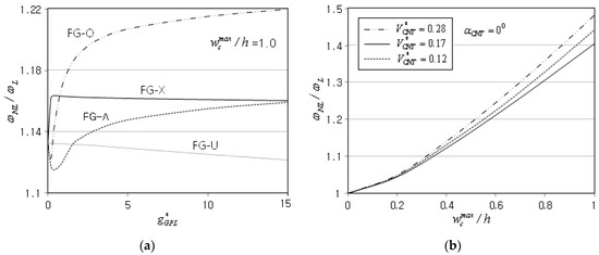
Figure 11.
Nonlinear-to-linear frequency ratio : (a) dependence on for and (b) for CNTRC with °.
Next, the influence of porosity on the nonlinear free vibration of a cracked FG-GPLRC cylindrical panel was investigated. The mass fraction and distribution pattern are 0.4% and FG-U, and the inclination angle and relative length of the crack are °. Three different porosity distributions and the five porosity parameters were considered.
Figure 12a comparatively represents the frequency ratios of an FG-U GPLRC cylindrical panel with the center-biased porosity distribution (PD_1). It is observed that the frequency ratio becomes uniformly smaller with the increase in until , but thereafter, it uniformly increases in proportion to . However, the extent of decrease becomes smaller as the porosity parameter increases. Both and decrease proportionally to because the increase in porosity decreases the structural stiffness [54]. But, the frequency ratio may increase with increasing because the denominator decreases in proportion to . Figure 12b compares the plots of for three different porosity distributions, where the center-biased distribution (PD_1) shows the highest level while the outer-biased distribution (PD_2) leads to the lowest level. This is because the structural stiffness increases as the porosity becomes biased towards the mid-surface of panel for the same amount of porosity. However, the relative difference in among the three porosity distributions becomes different when the GPL distribution pattern is changed, as will be seen next.
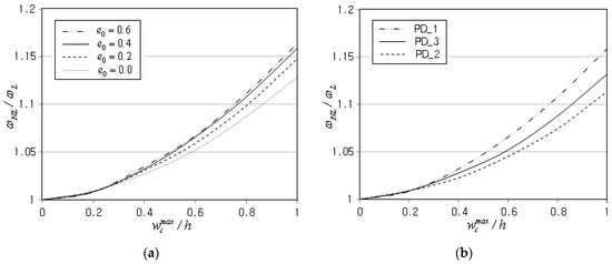
Figure 12.
Variation in nonlinear-to-linear frequency ratio (FG-U, , , °) (a) to the porosity parameter (PD-1) and (b) to the porosity distribution pattern ().
Figure 13a–d comparatively represent the differences in between three porosity distributions for FG-U, G-O, FG-X, and FG-∧. First of all, it is clearly observed that the relative order and difference in the three plots of are remarkably influenced by the GPL distribution pattern. In FG-O, shown in Figure 13b, the center-biased PD_1 shows the lowest level because the middle region with a high density of GPLs is mostly occupied with pores. On the other hand, the outer-biased PD_2 shows the highest level because most pores are concentrated in the top and bottom regions with a low density of GPLs. In FG-X, shown in Figure 13c, the difference between three porosity distributions is negligible. It is because the relative increase in with respect to is almost similar for the three porosity distributions as the amplitude–thickness ratio increases. Meanwhile, in FG-∧, shown in Figure 13d, the three porosity distributions show noticeable difference because the GPLs are concentrated only in the bottom region, differing from FG-X. Thus, it is found that the combination of GPL and porosity distributions leads to more diverse variations in the nonlinear-to-linear frequency ratio.


Figure 13.
Comparison of nonlinear-to-linear frequency ratios (, , °) (a) for FG-U, (b) for FG-O, (c) for FG-X, and (d) for FG-∧.
5. Conclusions
The nonlinear free vibration of a porous FG-GPLRC cylindrical panel with a central crack has been investigated by combining a phase field formulation and a virtual geometry rotation in the framework of 2-D XNEM. The curved neutral surface was transformed into a rectangular plane for the easy definition and manipulation of L/I functions, and the troublesome numerical locking was effectively suppressed by employing the MITC3+ shell concept and the stabilization factor. The developed nonlinear numerical method was verified through a comparison with the reference solutions, and the nonlinear free vibration characteristics of cracked porous FG-GPLRC cylindrical panels were profoundly examined. The numerical results led to the following major findings:
- The present method shows stable convergence and good agreement with the reference solutions, with a maximum relative difference equal to 4.838%.
- The nonlinear-to-linear frequency ratio decreases with increasing crack inclination angle, but the decreasing slope becomes saturated. Meanwhile, it uniformly decreases as the relative crack length becomes larger.
- The frequency ratio increases in proportion to the GPL mass fraction , but it becomes saturated as increases over a critical value. And, the saturation trend is different for different GPL distribution patterns.
- The frequency ratio increases proportionally to the porosity coefficient even though it shows a saturation trend. Also, its variation to is remarkably affected by the porosity distribution and becomes more diverse when the GPL distribution is combined.
- Compared with FG-GPLRC, FG-CNTRC produces a remarkably lower linear fundamental frequency but a slightly higher frequency ratio , for the same volume fraction. In addition, its nonlinear free vibration is affected by the CNT alignment direction, differing from FG-CNTRC.
Funding
This work was supported by the 2024 Hongik University Research Fund.
Data Availability Statement
The original contributions presented in the study are included in the article, further inquiries can be directed to the corresponding author.
Conflicts of Interest
The author declares no conflict of interest.
Appendix A. Interpolation of T/S Strains
The geometry transformation from the computational NEM grid to the physical NEM grid is defined by
Then, the L/I functions are mapped to , and the two relations and lead to the inverse Jacobi matrix given by
As well, the partial derivatives and in Equations (18)–(20) defined on the panel neutral surface are changed to
defined on the 2-D rectangular NEM grid according to the chain rule.
Introducing Equation (A3) into Equations (20)–(22) leads to and in which and are replaced with and :
Appendix B. Interpolation of T/S Strains
Each triangle in the physical NEM grid shown in Figure 4 is mapped to the three-node master element in Figure A1. And, the non-singular displacement part is re-expressed using the computed triangle-wise nodal vectors and the Lagrange-type bilinear shape functions . Next, according to the MITC3+ shell approach, the triangle-wise T/S strains are indirectly interpolated as
with , where A, B, C, D, E, and F indicate the six tying points, as shown in Figure A1.
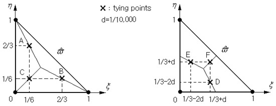
Figure A1.
Locations of the six tying points within the master triangular element .
References
- Shi, G.; Araby, S.; Gibson, C.T.; Meng, Q.; Zhu, S.; Ma, J. Graphene platelets and their polymer composites: Fabrication, structure, properties, and applications. Adv. Funct. Mater. 2018, 28, 1706705. [Google Scholar] [CrossRef]
- Soni, S.K.; Thomas, B.; Kar, V.R. A comprehensive review on CNTs and CNT-reinforced composites: Symtheses, characteristics and applications. Mater. Today Commun. 2020, 25, 101546. [Google Scholar] [CrossRef]
- Cho, J.R.; Ahn, Y.J. Investigation of mechanical behaviors of functionally graded CNT-reinforced composite plates. Polymers 2022, 14, 2664. [Google Scholar] [CrossRef] [PubMed]
- King, J.A.; Klimek, D.R.; Miskioglu, I.; Odegard, G.M. Mechanical properties of graphene nanoplatelet/epoxy composites. J. Compos. Mater. 2014, 49, 659–669. [Google Scholar] [CrossRef]
- Zegeye, E.; Ghamsari, A.K. Mechanical properties of grapheme platelets reinforced syntactic foams. Compos. Part B 2014, 60, 268–273. [Google Scholar] [CrossRef]
- Liew, K.M.; Jianwei, Y.; Zhang, L.W. Mechanical Behaviors of Carbon Nanotubes: Theoretical and Numerical Approaches; Elsevier: Amsterdam, The Netherlands, 2016. [Google Scholar]
- Cho, J.R.; Oden, J.T. Functionally graded material: A parametric study on thermal-stress characteristics using the Crack-Nicolson-Galerkin scheme. Comput. Methods Appl. Mech. Eng. 2000, 188, 17–38. [Google Scholar] [CrossRef]
- Suresh, S.; Giannakopoulos, A.E.; Olson, M. Elastoplastic analysis of thermal cycling: Layered materials with sharp interfaces. J. Mech. Phys. Solids 1994, 42, 978–1018. [Google Scholar] [CrossRef]
- Zhao, S.; Zhao, Z.; Yang, Z.; Ke, L.L.; Yang, J.; Kitipornchai, S. Functionally graded graphene reinforced composite structures: A review. Eng. Struct. 2020, 210, 110339. [Google Scholar] [CrossRef]
- Liew, K.M.; Pan, Z.; Zhang, L.W. The recent progress of functionally graded CNT reinforced composites and structures. Sci. China Phys. Mech. Astron. 2019, 63, 234601. [Google Scholar] [CrossRef]
- Zhu, J.C.; Lai, Z.H.; Jeon, J.; Lee, S. Fabrication of ZrO2-NiCr functionally graded material by powder metallurgy. Mater. Chem. Phys. 2001, 68, 130135. [Google Scholar] [CrossRef]
- Kieback, B.; Neubrand, A.; Riedel, H. Processing techniques for functionally graded materials. Mater. Sci. Eng. A 2003, 362, 81–105. [Google Scholar] [CrossRef]
- Setoodeh, A.R.; Shojaee, M.; Malekzadeh, P. Vibrational behavior of doubly curved smart sandwich shells with FG-CNTRC dace sheets and FG porous core. Compos. Part B Eng. 2019, 165, 798–822. [Google Scholar] [CrossRef]
- Yang, Z.; Wu, D.; Yang, J.; Lai, S.K.; Lv, J.; Fiu, J. Dynamic buckling of rotationally restrained FG porous arches reinforced with graphene nanoplatelets under a uniform step load. Thin-Walled Struct. 2021, 166, 108103. [Google Scholar] [CrossRef]
- Cho, J.R. Free vibration analysis of functionally graded porous cylindrical panels reinforced with graohene platelets. Nanomaterials 2023, 13, 1441. [Google Scholar] [CrossRef] [PubMed]
- Wu, H.; Yang, J.; Kitipornchai, S. Mechanical analysis of functionally graded porous structures: A review. Int. J. Struct. Stab. Dyn. 2020, 20, 2041015. [Google Scholar] [CrossRef]
- Young, R.J.; Kinloch, I.A.; Gong, I.; Novoselov, K.S. The mechanics of graphene nano composites: A review. Compos. Sci. Technolology 2012, 72, 1459–1476. [Google Scholar] [CrossRef]
- Rafiee, M.A.; Rafiee, J.; Wang, Z.; Song, H.; Yu, Z.Z.; Koratkar, N. Enhanced mechanical properties of nanocomposites at low graphene content. ACS Nano 2009, 3, 3884–3890. [Google Scholar] [CrossRef] [PubMed]
- Cho, J.R. Investigation of buckling behavior of cracked FG cylindrical panels reinforced by graphene platelets. Symmetry 2023, 15, 2162. [Google Scholar] [CrossRef]
- Halphin, J.C.; Kardos, J.L. The Haplin-Tsai equations: A review. Polym. Eng. Sci. 1976, 16, 344–352. [Google Scholar]
- Feng, C.; Kitipornchai, S.; Yang, J. Nonlinear free vibration of functionally graded polymer composite beams reinforced with graphene nanoplatelets (GPLs). Eng. Struct. 2017, 140, 110–119. [Google Scholar] [CrossRef]
- Zhang, L.W.; Zhang, Y.; Liew, K.M. Modeling of nonlinear vibration of graphene sheets using a meshfree method based on nonlocal elasticity theory. Appl. Math. Model. 2017, 49, 691–704. [Google Scholar] [CrossRef]
- Gao, K.; Gao, W.; Chen, D.; Yang, J. Nonlinear free vibration of functionally graded graphene platelets reinforced porous nanocomposite plates resting on elastic foundations. Compos. Struct. 2018, 204, 831–846. [Google Scholar] [CrossRef]
- Shen, H.S.; Xiang, Y.; Fan, Y.; Hui, D. Nonlinear vibration of functionally graded graphene-reinforced composite laminated cylindrical panels resting on elastic foundations in thermal environments. Compos. Part B Eng. 2018, 136, 177–186. [Google Scholar] [CrossRef]
- Kiani, Y. Isogeometric large amplitude free vibration of graphene reinforced laminated plates in thermal environment using NURBS formulation. Comput. Methods Appl. Mech. Eng. 2018, 332, 86–101. [Google Scholar] [CrossRef]
- Teng, M.W.; Wang, Y.Q. Nonlinear free vibration of rectangular plates reinforced with 3D graphene form: Approximate analytical solution. Results Phys. 2020, 17, 103147. [Google Scholar] [CrossRef]
- Song, M.; Gong, Y.; Yang, J.; Zhu, W.; Kitipornchai, S. Nonlinear free vibration of cracked functionally graded graphene platelet-reinforced nanocomposite beams in hermal environments. J. Sound Vib. 2020, 468, 115115. [Google Scholar] [CrossRef]
- Tao, C.; Dai, T. Isogeometric analysis for size-dependent nonlinear free vibration of graphene platelet reinforced laminated annular sector microplates. Eur. J. Mech.-A/Solids 2021, 86, 104171. [Google Scholar] [CrossRef]
- Javani, M.; Kiani, Y.; Eslami, M.R. Geometrically nonlinear free vibration of FG-GPLRC circular plate on nonlinear elastic foundation. Compos. Struct. 2021, 261, 113515. [Google Scholar] [CrossRef]
- Wang, Y.; Chen, J. Nonlinear free vibration of rotating functionally graded graphene platelets reinforced blades with variable cross-sections. Eng. Anal. Bound. Elem. 2022, 144, 262–278. [Google Scholar] [CrossRef]
- Wang, K.; Chen, L.; Wu, J.; Toh, M.L.; He, C.; Yee, A.F. Epoxy nanocomposites with highly exfolidated clay: Mechcanical propertiesand fracture mechanisms. Macromolecules 2005, 38, 788–800. [Google Scholar] [CrossRef]
- Moes, N.; Dolbow, J.; Belytschko, T. A finite element method for crack growth without remeshing. Int. J. Numer. Methods Eng. 1999, 46, 131–150. [Google Scholar] [CrossRef]
- Cho, J.R. Near-tip grid refinement for the effective and reliable natural element crack analysis. Struct. Eng. Mech. 2019, 70, 279–287. [Google Scholar] [CrossRef]
- Wang, C.; Wang, Y.; Cui, B.; Duan, L.; Ma, N.X.; Feng, J.Q. Numerical simulation of distortion-induced fatigue crack growth using extended finite element method. Struct. Infrastruct. Eng. 2020, 16, 106–122. [Google Scholar] [CrossRef]
- Ambati, M.; Gerasimov, T.; De Lorenzis, L. A review on phase-field models of brittle fracture and a new fast hybrid formulation. Comput. Mech. 2015, 55, 383–405. [Google Scholar] [CrossRef]
- Torabi, J.; Ansari, R. Numerical investigation on the buckling and vibration of cracked FG cylindrical panels based on the phase-field formulation. Eng. Fract. Mech. 2020, 228, 106895. [Google Scholar] [CrossRef]
- Mohammadi, S. Extended Finite Element Method: For Fracture Analysis of Structures; John Wiley & Sons: Hoboken, NJ, USA, 2008. [Google Scholar]
- Bayesteh, H.; Mohammadi, S. XFEM fracture analysis of shells: The effect of crack tip enrichments. Comput. Mater. Sci. 2011, 50, 793–813. [Google Scholar] [CrossRef]
- Cho, J.R.; Oden, J.T. Locking and boundary layer in hierarchical models for thin elastic structures. Comput. Methods Applies Mech. Eng. 1997, 149, 33–48. [Google Scholar] [CrossRef]
- Pitkaranta, J. The problem of membrane locking in finite element analysis of cylindrical shells. Numner Ische Mathmatik 1992, 61, 523–542. [Google Scholar] [CrossRef]
- Lee, Y.; Lee, P.S.; Bathe, K.J. The MITC3+shell finite element and its performance. Comput. Struct. 2014, 138, 12–23. [Google Scholar] [CrossRef]
- Cho, J.R. Neutral surface-based static and free vibration analysis of functionally graded porous plates. Steel Compos. Struct. 2023, 49, 431–440. [Google Scholar]
- Gibson, L.J.; Ashby, M.F. The mechanics of three-dimensional cellular materials. Proc. R. Soc. Lond. A Math. Phys. Eng. Sci. R. Soc. 1982, 382, 43–59. [Google Scholar]
- de Borst, R.; Verhoosel, C.V. Gradient damage vs phase-field approaches for fracture: Similarities and differences. Comput. Methods Appl. Mech. Eng. 2016, 312, 78–94. [Google Scholar] [CrossRef]
- Hirshikesh; Natarajan, S.; Annabattula, R.K.; Martinez-Paneda, E. Phase field modeling of crack propagation in functionally graded materials. Compos. Part B Eng. 2019, 169, 239–248. [Google Scholar] [CrossRef]
- Cho, J.R.; Lee, H.W. A Petrov-Galerkin natural element method securing the numerical integration accuracy. J. Mech. Sci. Technol. 2006, 20, 94–109. [Google Scholar] [CrossRef]
- Sukumar, N.; Moran, B.; Belytschko, T. The natural element method in solid mechanics. Int. J. Numer Methods Eng. 1998, 43, 839–887. [Google Scholar] [CrossRef]
- Cho, J.R. Nonlinear free vibration of functionally graded CNT-reinforced composite structures. Compos. Struct. 2022, 281, 115101. [Google Scholar] [CrossRef]
- Shin, D.K. Large amplitude free vibration behavior of doubly curved shallow open shells with simply-supported edges. Comput. Struct. 1997, 62, 35–49. [Google Scholar] [CrossRef]
- Shen, S.H.; Xiang, Y. Nonlinear vibration of nanotube-reinforced composite cylindrical panels resting on elastic foundations in thermal environments. Compos. Struct. 2014, 111, 291–300. [Google Scholar] [CrossRef]
- Kelesdhteri, M.; Jelovica, J. Nonlinear vibration behavior of fuctionally graded porous cylindrical panels. Compos. Struct. 2020, 239, 112028. [Google Scholar] [CrossRef]
- Liang, Z.; Gou, J.J.; Zhang, C.; Wang, B.; Kramer, L. Investigation of molecular interactions between (10,10) single-walled nanotube and Epon 862 resin/DETDA curing agent molecules. Mater. Sci. Eng. A 2004, 365, 228–234. [Google Scholar] [CrossRef]
- Zhu, P.; Lei, Z.X.; Liew, K.M. Static and free vibration analyses of carbon nanotube-reinforced composite plates using finite element method with first order shear deformation plate theory. Compos. Struct. 2012, 94, 1450–1460. [Google Scholar] [CrossRef]
- Cho, J.R. Large deflection geometrically nonlinear bending of porous nanocomposite cylindrical panels on elastic foundation. Symmetry 2024, 16, 224. [Google Scholar] [CrossRef]
Disclaimer/Publisher’s Note: The statements, opinions and data contained in all publications are solely those of the individual author(s) and contributor(s) and not of MDPI and/or the editor(s). MDPI and/or the editor(s) disclaim responsibility for any injury to people or property resulting from any ideas, methods, instructions or products referred to in the content. |
© 2024 by the author. Licensee MDPI, Basel, Switzerland. This article is an open access article distributed under the terms and conditions of the Creative Commons Attribution (CC BY) license (https://creativecommons.org/licenses/by/4.0/).