Abstract
Compliant bistable mechanisms with planar configurations demonstrate two in-plane stable states through the nonlinear deformations of in-plane flexible segments, which are widely used in the field of shock sensors and threshold sensors. In these mechanisms, consistent dynamic and static bistable behaviors are difficult to maintain under the influence of an out-of-plane load. This is limited in some applications where precise displacement is required. To this end, we developed a bistable mechanism with circular beams instead of conventional straight beams, such that enhanced robustness against external loads in the out-of-plane region is obtained. An analytical kinetostatic model is established to predict the bistable behavior of the proposed mechanism, which is further verified using finite element simulations and experimental results. Compared with the prototype of the straight-beam-based bistable mechanism, the developed circular-beam bistable mechanism demonstrates improved pitch stiffness along the out-of-plane rotation and robustness against off-axis load conditions. The proposed bistable mechanism design can be extended to applications of sensors subjected to out-of-plane loads.
1. Introduction
1.1. Background
Compliant mechanisms realize their function through the elastic deformation of their structure [1]. Although compliant mechanisms have a limited range of elastic deformation, they are used in various important applications due to their simplicity, passive holding, low actuation energy, small footprint, large stroke with small restoring forces, and negative stiffness zone [2].
The compliant bistable mechanism is a mechanical structure that maintains two different stable states without requiring an external energy input. There is a deflection range between the two different stable states, which is also the motion displacement of the compliant bistable mechanism. This mechanism is promising for applications in systems that require two operating states, such as switches [3], grippers [4,5], energy harvesters [6,7], soft actuators [8], and metamaterials [9]. Various types of compliant bistable mechanisms are available, such as the compliant four-link bistable mechanism [10,11], compliant tensural–compresural bistable mechanism [12], Young bistable mechanism [13], and bistable mechanism using curved-beam plates [14]. However, they are generally designed to transform between the two steady states in a plane. Therefore, out-of-plane deflection is rarely considered in the design. When off-axis or eccentric loads are present, the out-of-plane motion of the shuttle results in the bistable behavior of the mechanism [15]. For example, when utilized for shock sensors and threshold gyroscopes [16,17], the bistable mechanisms must maintain consistent bistable behavior while in motion to maintain sensing accuracy.
1.2. Motivation
The shape of the bistable beams can be obtained by initial bucking or by pre-shaping during fabrication (Figure 1), resulting in bistable mechanisms with different shapes and specific characteristics, thereby expanding the possibilities to study bistable mechanisms. The flexible beams are mainly subjected to in-plane bending deformation deflections (often accompanied by axial deflections) [18]. Thus, out-of-plane deflections are rarely considered during design. In practice, however, compliant bistable mechanisms need to maintain consistent kinematic–static behavior when switching between two stable equilibrium positions [19]. When the compliant bistable mechanism is subjected to an out-of-plane load, as illustrated in Figure 2, its kinematic–static behavior will be significantly affected [15], resulting in motion inconsistency of the bistable mechanism. These changes will affect the behavior prediction of the entire mechanism. For the traditional straight-beam bistable mechanism (SBBM), when subjected to out-of-plane load, the shuttle will produce out-of-plane deflection, which will affect the motion consistency of the bistable mechanism, thus reducing the accuracy of the sensor. Therefore, improving the ability of a bistable mechanism to resist out-of-plane deformation has become a research focus.
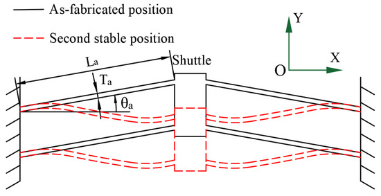
Figure 1.
Fully compliant bistable mechanism.
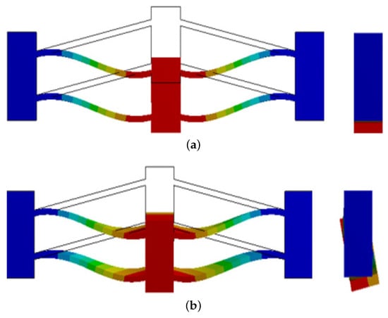
Figure 2.
(a) Compliant bistable mechanism deflection unaffected by off-axis or eccentric load; (b) Compliant bistable mechanism deflection affected by off-axis or eccentric load.
Inspired by the bistable buckled straight-beam mechanism, we select a circular beam instead of a straight beam to obtain a high-performance bistable mechanism. The shape of the bistable circular beams can be pre-shaped during fabrication. Thus, circular beam can provide advantages during beam buckling compared with the conventional straight beam. Given the increased length between the same endpoints, the circular beam shows a more even distribution of stress, greater flexibility during deformation, and higher bistable performance [20].
1.3. Contributions
In this work, we introduce a fully compliant bistable mechanism based on circular beams to restrain torsional deflections while retaining bending deflections. Using this design ensures higher resistance to the out-of-plane deformation of a shuttle, even when the bistable model is subjected to centrifugal loading, thus guaranteeing a consistent kinetostatic behavior of the bistable mechanism. Compared with the SBBM, the circular-beam bistable mechanism (CBBM) can reduce the inhomogeneity of the stress and deformation and improve the torsional stiffness owing to its increased length and curvature, thereby allowing it to better withstand out-of-plane deformation considering that altering the mechanism kinematics may lead to inconsistent bistable behavior. In some applications where anti-centrifugal force is required, the proposed CBBM can significantly reduce the effect of centrifugal force, thus maintaining the consistency of the bistable mechanism.
The rest of this paper is organized as follows. Section 2 presents the principles and design of the proposed CBBM. Section 3 details a derived dynamic model applicable for the CBBM. Section 4 demonstrates the accuracy of the proposed dynamic model through finite element analysis and shows that the CBBM has a higher resistance to out-of-plane deformations than a conventional mechanism. Section 5 reports various characteristics of the proposed mechanism through experiments, includinghe effect of changing the geometric dimensions on the pitch stiffness. Finally, we draw conclusions in Section 6.
2. CBBM Design
Owing to the complex coupling effects among different bistable mechanical properties, it is difficult to modify a specific bistable characteristic without affecting others by just modifying the structure parameters, given a fixed bistable configuration and boundary constraints [21]. Therefore, to improve the pitch stiffness of a bistable mechanism, changes in the other characteristics of the bistable mechanism should be prevented. This improvement can be achieved by reducing the deflection of the shuttle when it is subjected to an off-axis force [22]. Increasing the thickness of the flexible beam increases its twist resistance but affects its nonlinear deformation [23]. In addition, the overall structure becomes larger, which undermines the applicability of flexible bistable mechanisms when a low driving energy and small footprint are required [24].
As the thickness of the flexible beam gradually increases, a negative stiffness interval appears, but the force direction does not change. Consequently, no bistable behavior occurs and the mechanism cannot reach the second stable position [25]. In addition, increasing the in-plane area of the bistable flexible beam by simply increasing its thickness adversely affects the performance of the bistable mechanism. Alternatively, the out-of-plane bending resistance of the flexible bistable mechanism can be improved by changing the shape of the flexible beam.
We use circular beams instead of straight beams with the same endpoints to increase the in-plane area of the flexible segment and thereby enhance the pitch stiffness. The proposed CBBM is symmetrical about the center and each side consists of three parts, namely, compliant beams at both ends and a rigid beam in the middle, which have the same circle center, where the compliant beams, as well as the steady-state beam, are parts of the circular beam (Figure 3). This design can enhance the stability of a single flexible limb and improve the resistance of the bistable mechanism to out-of-plane deformation. The size of the CBBM is determined by the diameter D of the circular beam and central angle of each circular beam. In addition, the chord length of the arc of the beam determines the size of the bistable branch and is the thickness of the beam.
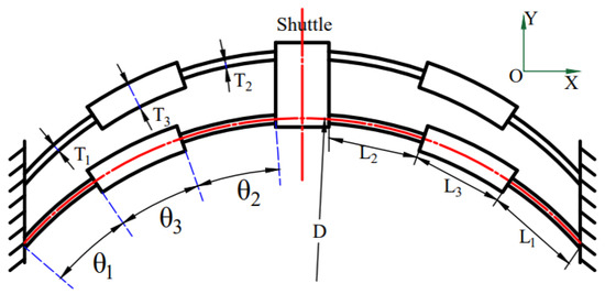
Figure 3.
Fully compliant CBBM.
3. Kinetostatic Model
Considering that the fully compliant bistable mechanism is symmetrically distributed, we only need to analyze one side of the model. One fixed-guided limb of the circular beam bistable mechanism is composed of two flexible circular beams and one rigid circular beam. The major geometric parameters are also shown in Figure 3. The beam constraint model (BCM) can be used to predict the force–displacement relationship of the flexible beams, thereby modeling the nonlinear behavior of flexible beams simply and accurately [26]. Accordingly, we use the chain BCM (CBCM) to model the circular bistable flexible beam. The CBCM discretizes the flexible beam into multiple flexible elements and models each element separately using the BCM. The CBCM can be discretized to eliminate some restrictions of the BCM on the curvature and tangential forces when modeling curved beams [27].
3.1. CBCM for Circular Beams
When applying the CBCM to circular beams, the BCM of the circular beams should be first analyzed, as shown in Figure 4. The radius of the curved beam is R and the end of the curved beam is subjected to horizontal force , vertical force , and counterclockwise moment , resulting in tangential and radial deflections and , respectively, and end slope . The geometric parameters of the curved beam include length L along the axis, in-plane thickness , out-of-plane thickness W, and Young modulus E of the material. In addition, represents the area moment of inertia of the beam cross-section. The dimensionless curvature is defined as
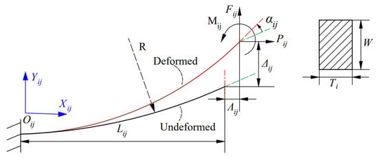
Figure 4.
Circular beam subjected to combined force and moment loads at its free end.
The sign of k indicates the rotation direction of the unit tangent vector according to the parameter along the curve. If the unit tangent rotates counterclockwise, ; if it rotates clockwise, . For the flexible circular beam (), the curvature is constant and the CBCM can be used for equal discretization, as shown in Figure 5.
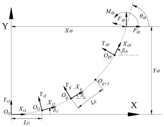
Figure 5.
Discretization of circular beam at its undeformed position.
After discretization, we use the BCM to describe each element independently. In thelocal coordinate system for element j of flexible beam i, , and are the radial, tangential, and moment forces at the ends of the element, respectively, and , and are the corresponding tangential and radial deflections and end slope, respectively, as shown in Figure 6. All the parameters are normalized as follows:
where all the load and deflection parameters (, , , , , and ) are normalized with respect to the beam parameters. The variables , , and are the nondimensionalized radial deflection, tangential deflection, and thickness of the element i.
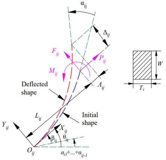
Figure 6.
Element at its deflection position.
Referring to [27], we have the following relationships according to the BCM for a circular beam:
The end of the beam is balanced with the load of the first element:
The static equilibrium between elements is provided by
and the torque balance can be expressed as
The geometric constraints are expressed as
and
where is the slope of the element of the circular beam and is the rotation angle of the coordinate system of the element relative to the global coordinate system.
The force–deformation relationship of a single flexible segment can be obtained from Equations (1)–(9).
3.2. CBCM of Three-Stage CBBM
As shown in Figure 7, the local coordinate system is defined at the fixed end, , of the first flexible beam, and the local coordinate system is defined at the fixed end of the second flexible beam. and represent the lengths of the two flexible beams along directions and in the local coordinate systems and , respectively. As the deformation of the rigid beam is much smaller than that of the flexible beam, length of the rigid beam can be expressed as the length of the line connecting points A and B. and represent the angles between local coordinate systems and and natural coordinate system , respectively, and represents the angle between the line connecting points A and B and the X axis in the natural coordinate system. Owing to the geometric nonlinear deformation of the internal flexible beam of the bistable mechanism during motion, modeling is complicated. We adopt the CBCM to describe the flexible bistable mechanism. The CBCM discretizes the initial circular beam into N elements, which are separately modeled using the BCM. Through discretization, the CBCM eliminates the limitation of the BCM for describing curved beams.
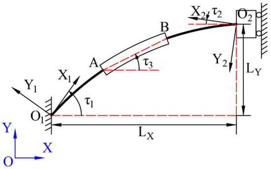
Figure 7.
Geometric parameters of circular-beam bistable limb.
Figure 8 shows the free body diagram of the bistable limbs of the proposed CBBM with load balance to the intermediate rigid segment.
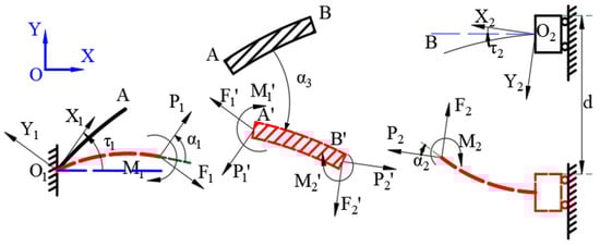
Figure 8.
Free body diagram of circular-beam bistable limb in proposed mechanism.
When the displacement of the intermediate shuttle is d, the deflection geometry of flexible circular beam i is provided by [28]:
In addition,
The geometric relationship when the shuttle displacement is d is expressed as
The load balance for the second flexible beam column can be obtained as follows:
where is the input force required to displace the mechanism and is the number of fixed limbs bistabiles. The CBBM force–deformation relationship provided by the CBCM can be obtained from Equations (9)–(17). The relationship between and d was solved by using the ‘fsolve’ function in MathWorks MATLAB.
4. Finite Element Simulations
To verify the correctness of modeling, we used the finite element software ANSYS Workbench to simulate the proposed CBBM. To ensure comparability among the three models, the default size of the mesh was used. To demonstrate that the pitch stiffness of the CBBM increases, we considered two SBBMs. Based on the proposed CBBM, two compliant SBBMs were established for comparisons. The SBBMs adopted a three-stage design with the structure shown in Figure 9. The bistable fixed limb arms of the SBBM and CBBM had the same end points. SBBM1 and SBBM2 replace a bistable circular beam limb of the CBBM (including two flexible segments and one rigid segment) with a straight beam of the same thickness. The two flexible segments and one rigid segment of SBBM1 have the same horizontal angle. The bistable beam of SBBM1 represents the chord length of the circular bistable beam of CBBM, as shown in Figure 9a. The horizontal angle of the flexible section of SBBM2 is different from that of the rigid section and the three-section bistable beam of SBBM2 corresponds to the chord length of the three-section bistable beam of the CBBM, as shown in Figure 9b.
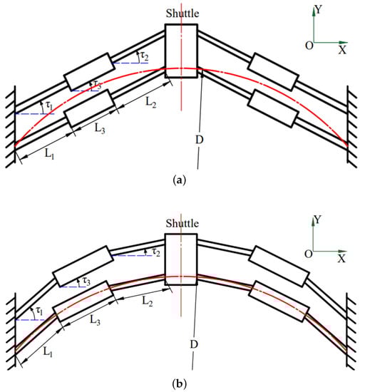
Figure 9.
(a) Geometric parameters of SBBM1; (b) Geometric parameters of SBBM2.
The three designs were analyzed and compared using finite element simulations to demonstrate the enhanced pitch stiffness of the CBBM and modeling accuracy. Table 1 lists the geometric parameters of the three evaluated designs.

Table 1.
Geometric parameters of evaluated bistable mechanisms.
4.1. Simulation Results
In the finite element analysis, the mesh was automatically divided, the mesh size was set at 2 mm, and the material of the mechanism was PA12 nylon with a Young’s modulus of Pa. The static structural module of Workbench was used for the analysis. After the mesh division was set and the flexible large deformation switch was opened, the two ends of the bistable mechanism were fixed constraints and the middle shuttle of the bistable mechanism was shifted by 0–10.5 mm in the form of a displacement increment. The finite element deformation nephograms of CBBM, SBBM1, and SBBM2 were then obtained, as shown in Figure 10a, Figure 10b, and Figure 10c, respectively. The reaction force of the shuttle in the process of displacement was calculated using the ’Force Reaction’ function. The specific force–displacement curve is shown in Figure 10d. The tilt angle of the bistable beam of SBBM1 is large and its critical force when deflecting is higher than that of CBBM and SBBM2. However, the second steady-state position of the three bistable mechanisms is similar (d with the maximum error is 4.4%). When we compare the pitch stiffness of the three bistable mechanisms, the other bistable properties of the bistable mechanisms are similar, including their motion tendency to the second stable position and the displacements all being close. When applied to some sensors, the three bistable mechanisms have certain interchangeability, which provides us with the possibility to compare the pitch stiffness of the three bistable mechanisms.
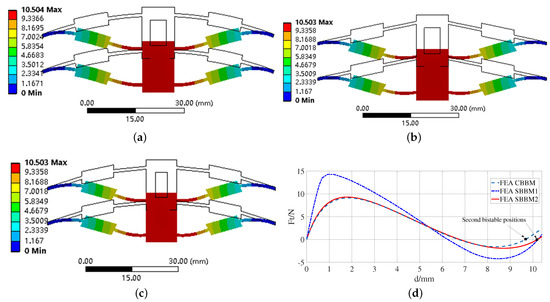
Figure 10.
(a) Finite element model of CBBM; (b) Finite element model of SBBM1; (c) Finite element model of SBBM2; (d) force−displacement curves of CBBM, SBBM1, and SBBM2 using finite element analysis.
4.2. Finite Element Simulation for Pitch Stiffness
In another finite element simulation, since the deformation process of a bistable mechanism is an instantaneous behavior under the same boundary conditions, we applied the 50 N·mm of torque at different displacement positions of the shuttle using the CBBM model to obtain the corresponding pitch stiffness, which allows us to observe the variation trend of the pitch stiffness of the bistable mechanism in the process of motion; a finite element model can be used to better express the results. The results are shown in Figure 11.
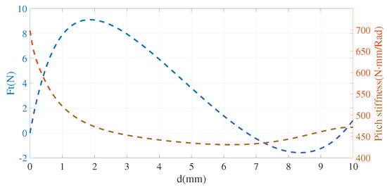
Figure 11.
Pitch stiffness−displacement curve of CBBM.
The pitch stiffness of the CBBM gradually decreases with increasing bistable displacement. Its pitch stiffness slightly improves when the bistable mechanism is close to the second stable position. Compared with the initial position, a 31% reduction in pitch stiffness occurs at the second stable position. When the mechanism moves, the bistable limbs buckle and deform and the beam state becomes unstable. Consequently, the beam exhibits low pitch stiffness. In the second steady state, the buckling deformation of the bistable beam reaches an equilibrium position and the pitching stiffness is improved. To prove that the CBBM is superior to SBBMs 1 and 2 regarding their resistance to out-of-plane deformation, we performed finite element simulations to calculate the pitch stiffness of the three bistable mechanisms at different displacements and obtained the results shown in Figure 12.
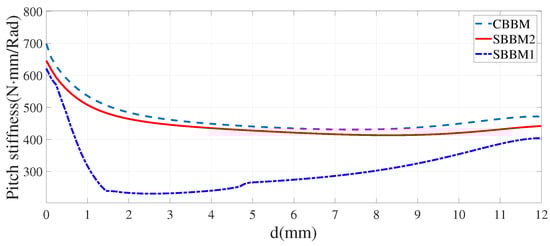
Figure 12.
Pitch stiffness of CBBM and SBBMs 1 and 2 at different shuttle displacements.
The pitch stiffness of the CBBM is 698.3 (N · mm)/Rad and that of SBBMs 1 and 2 is 607 and 634.2 (N · mm)/Rad, respectively. The pitch stiffness of the CBBM increases by 15.0% and 10.1% compared with that of SBBMs 1 and 2, respectively. At the second stable position, the pitch stiffness of the CBBM is 481.1 (N · mm)/Rad, while that of SBBM 1 is 363 (N · mm)/Rad, and that of SBBM 2 is 426.3 (N · mm)/Rad. Thus, the pitch stiffness of the CBBM increases by 32.5% and 12.8% compared with that of SBBMs 1 and 2, respectively.
5. Experiments
5.1. Force–Displacement Relationship
Three prototypes (CBBM and SBBMs 1 and 2) were fabricated using 3D printing based on selective laser sinteringwith HP PA12 nylon with a Young’s modulus of Pa, obtaining the samples shown in Figure 13. The experimental setup established to measure the second stable position of the bistable mechanisms and validate the proposed CBCM is shown in Figure 14. A dynamometer was installed on a uniaxial displacement platform and the displacement data of the platform were read through a digital dial indicator (Mitutoyo 543-390B). We obtained the force–displacement relationship of the flexible bistable mechanism shown in Figure 15.
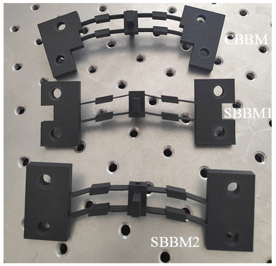
Figure 13.
Photographs of prototype CBBM and SBBMs 1 and 2.
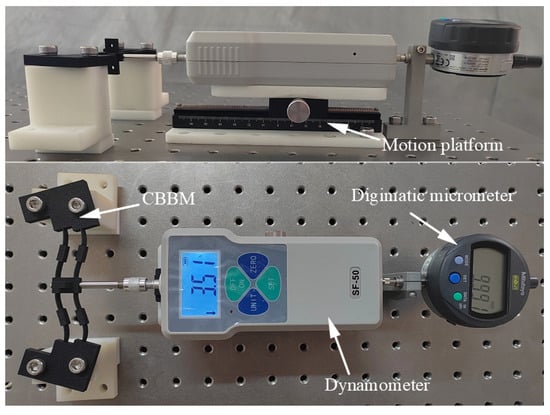
Figure 14.
Experimental setup for measuring force−displacement curves.
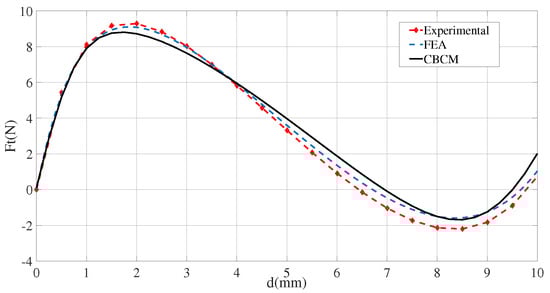
Figure 15.
Bistable curves of CBBM.
Figure 15 compares the CBBM force−displacement curves predicted by the CBCM and finite element model with the measured curves. The second stable positions of the circular beam expressed by the force−displacement curves obtained from the experiment, model (with the maximum error less than 5%), and simulation suitably agree, indicating the correctness of the derived model. It can be seen that both the kinetostatic model and the finite element model successfully observed the bistable behaviors of CBBM and produced reasonable predictions for the second steady-state positions.
5.2. Anti−Torsion Test
To further verify the effectiveness of the compliant CBBM to enhance the pitch stiffness, forces of equal magnitude and opposite directions were applied to the shuttles of CBBM and SBBMs 1 and 2 and a rotational moment was applied to the intermediate shuttle (Figure 16). A laser displacement sensor (KEYENCE LK−H020) was used to measure the rotation of the shuttle body. For each bistable mechanism, the displacement was measured at different stable positions and under the action of no moment. The average values under different moments were then measured to obtain the pitch stiffness.
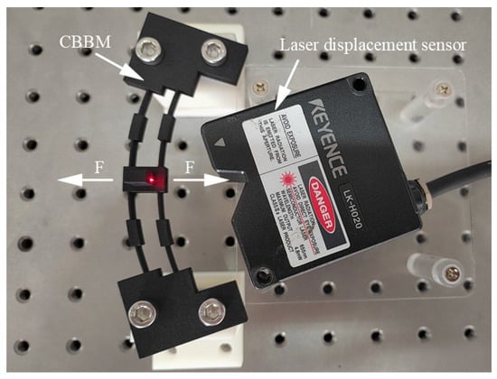
Figure 16.
Pitch stiffness in experimental setup.
As shown in Figure 17, during the experiment, the deflection radians of different bistable mechanisms at different steady-state positions were obtained by applying different amounts of torque. The value of the cotangent of the lines was the pitch stiffness of the bistable mechanisms at this position. By comparing different lines, we can see that the pitch stiffness of the CBBM is greater than that of the SBBMs at different steady-state positions.
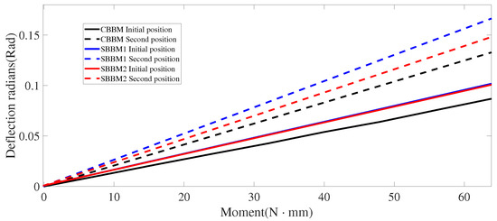
Figure 17.
Experimental curve of moment and deflection radians of bistable mechanisms.
Table 2 lists the simulation and experimental results. The experimental results show that the pitch stiffness of the CBBM at different stable positions is higher than that of the SBBMs. Compared with SBBM1, the pitch stiffness of the CBBM increases by 19.8% at the initial position and 28.2% at the second position. Compared with SBBM2, the pitch stiffness of the CBBM increases by 15.2% at the initial position and 11.5% at the second position. The error of the finite element and experimental results of CBBM is 6.6% at the initial position and 1.8% at the second position. The error of the finite element and experimental results of SBBM1 is 2.3% at the initial position and the error in the second position is 4.8%. The error of the finite element and experimental results of SBBM2 is 1.8% in the initial position and 2.9% in the second position, mainly because of dimension errors during fabrication. Thus, the out-of-plane deformation resistance of the CBBM is higher than that of the SBBM.
Table 2.
Comparison between simulation and experimental results of pitch stiffness in different structures.
5.3. Discussion
To analyze the sensitivity of the CBBM pitch stiffness to various parameters, we changed diameter D of the circular beam and central angle of the flexible segment by fixing one parameter while varying the other. The sensitivity of the CBBM to the varied parameter was analyzed using finite element simulations.
As shown in Figure 18, the pitch stiffness increases with the decreasing diameter. When we keep the total central angle of the bistable limb fixed (i.e., length of the bistable limb does not change), a change in the length of the flexible beam for equal lengths of the two flexible beams decreases the CBBM pitch stiffness with a lengthening flexible segment. For a fixed central angle of the flexible beam, when the diameter of the circular beam gradually changes from 204 to 194 mm, the pitch stiffness increased by 13.5%. For a fixed diameter of the circular beam, when the central angle of the flexible beam gradually changes from 4 to 9, the pitch stiffness decreases by 52%.
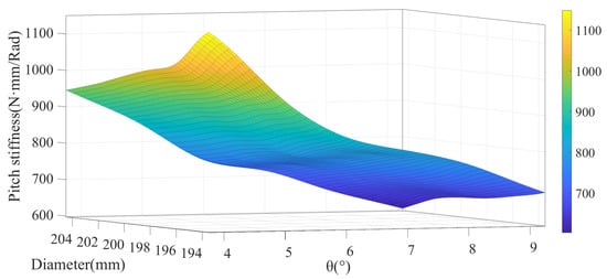
Figure 18.
Influence of geometric parameters of bistable mechanism on pitch stiffness.
When the central angle of the circular beam of the bistable beam remains unchanged, the central angle of the rigid beam increases if the central angle of the flexible circular beam decreases. In other words, the length of the flexible circular beam decreases, while the length of the rigid circular beam increases. The in-plane area of the rigid circular beam is larger than that of the flexible circular beam. Therefore, reducing the central angle of the flexible circular beam increases the in-plane area of the bistable mechanism of the circular beam. This increases the ability of the CBBM to resist out-of-plane loads and increases the pitch stiffness of the CBBM. Similarly, reducing the radius of the CBBM reduces the length of the flexible beam. The shift of the CBBM mainly depends on the nonlinear deformation of the flexible beam. As the length of the flexible beam decreases, the load required for deformation increases, which increases the deformation resistance of the circular beam.
According to the experimental results and finite element simulations, the CBBM exhibits a significant improvement in increasing the pitch stiffness. In some application scenarios where the bistable mechanism is required to be used as a sensor, the actual force received by the sensor cannot be guaranteed to be perpendicular to the plane where the bistable mechanism is located and there must be some off-axis load. When the impact of an off-axis load occurs, the CBBM allows for better motion consistency without compromising the senso accuracy.
6. Conclusions
To improve the out-of-plane bending resistance of a compliant bistable mechanism and elicit consistent bistable behavior, we developed a fully compliant CBBM and derived a theoretical model based on the CBCM. By establishing the experimental comparison of the pitch stiffness of SBBMs 1 and 2 and the CBBM, we can obtain the mechanical properties of the proposed CBBM and the effectiveness of resisting unnecessary loads and deformations. Compared with SBBM1, the pitch stiffness of the CBBM was increased by 19.8% and 28.2% in the initial and second positions, respectively. Compared with SBBM2, the pitch stiffness of the CBBM was increased by 15.2% and 11.5% in the initial and second positions, respectively. The error between the experimental and simulation results is 6.6%. Along this research line, we will investigate the applications of the developed CBBM in energy harvesting and mechanical metamaterials as future work.
In addition, from the above analysis, we can draw the following conclusions:
1. It can be seen that both the kinetostatic and finite element models successfully observe the bistable behaviors of the CBBM and produce reasonable predictions for the second steady-state positions (with a maximum error less than 5%).
2. The experimental results show that, compared with the two SBBMs, the pitch stiffness of the CBBM increases, and the kinetostatic behaviors of the CBBM are more robust against off-axis or eccentric loads. The pitch stiffness of the CBBM increases with a decrease in the diameter and decreases with an increase of the central angle in the flexible circular beam.
Author Contributions
Conceptualization, L.Y. and P.L.; methodology, L.Y.; software, L.Y.; validation, L.Y., S.L., and P.L.; formal analysis, L.Y.; investigation, P.L.; resources, P.L.; data curation, L.Y.; writing—original draft preparation, L.Y.; writing—review and editing, L.Y.; supervision, P.L.; project administration, S.L.; funding acquisition, S.L. and P.L. All authors have read and agreed to the published version of the manuscript.
Funding
This research was funded by the National Natural Science Foundation of China under Grant 51905287 and the Natural Science Foundation of Shandong Province under Grant ZR2022QE235.
Institutional Review Board Statement
Not applicable.
Informed Consent Statement
Informed consent was obtained from all subjects involved in the study.
Data Availability Statement
The data presented in this study are available on request from the corresponding author. Due to specific data of the experiment have been published in the article.
Acknowledgments
We would like to thank the financial support from the National Natural Science Foundation of China under Grant 51905287 and the Natural Science Foundation of Shandong Province under Grant ZR2022QE235.
Conflicts of Interest
The authors declare no conflict of interest.
Abbreviations
The following abbreviations are used in this manuscript:
| SBBM | Straight-beam bistable mechanism |
| CBBM | Circular-beam bistable mechanism |
| BCM | Beam constraint model |
| CBCM | Chain-beam constraint model |
References
- Kirmse, S.; Campanile, L.F.; Hasse, A. Synthesis of compliant mechanisms with selective compliance–An advanced procedure. Mech. Mach. Theory 2021, 157, 104184. [Google Scholar] [CrossRef]
- Medina, L.; Gilat, R.; Krylov, S. Bistable behavior of electrostatically actuated initially curved micro plate. Sens. Actuators Phys. 2016, 248, 193–198. [Google Scholar] [CrossRef]
- Liu, M.; Wu, X.; Niu, Y.; Yang, H.; Zhu, Y.; Wang, W. Research Progress of MEMS Inertial Switches. Micromachines 2022, 13, 359. [Google Scholar] [CrossRef]
- Chang, P.L.; Chi, I.T.; Tran, N.D.K.; Wang, D.A. Design and modeling of a compliant gripper with parallel movement of jaws. Mech. Mach. Theory 2020, 152, 103942. [Google Scholar] [CrossRef]
- Mouazé, N.; Birglen, L. Bistable compliant underactuated gripper for the gentle grasp of soft objects. Mech. Mach. Theory 2022, 170, 104676. [Google Scholar] [CrossRef]
- Chen, K.; Ding, X.; Tian, L.; Shen, H.; Song, R.; Bian, Y.; Yang, Q. An M- shaped buckled beam for enhancing nonlinear energy harvesting. Mech. Syst. Signal Process. 2023, 188, 110066. [Google Scholar] [CrossRef]
- Fan, Y.; Ghayesh, M.H.; Lu, T.F.; Amabili, M. Design, development, and theoretical and experimental tests of a nonlinear energy harvester via piezoelectric arrays and motion limiters. Int. J. Non-Linear Mech. 2022, 142, 103974. [Google Scholar] [CrossRef]
- Li, B.; Jiang, L.; Ma, W.; Zhang, Y.; Sun, W.; Chen, G. A Switchable Dual-Mode Actuator Enabled by Bistable Structure. Adv. Intell. Syst. 2022, 4, 2100188. [Google Scholar] [CrossRef]
- Kadic, M.; Milton, G.W.; van Hecke, M.; Wegener, M. 3D metamaterials. Nat. Rev. Phys. 2019, 1, 198–210. [Google Scholar] [CrossRef]
- Cai, C.; Zhou, J.; Wang, K.; Pan, H.; Tan, D.; Xu, D.; Wen, G. Flexural wave attenuation by metamaterial beam with compliant quasi-zero-stiffness resonators. Mech. Syst. Signal Process. 2022, 174, 109119. [Google Scholar] [CrossRef]
- Ma, F.; Chen, G. Influence of non-ideal fixed-end constraints on kinetostatic behaviors of compliant bistable mechanisms. Mech. Mach. Theory 2019, 133, 267–277. [Google Scholar] [CrossRef]
- Han, Q.; Jin, K.; Chen, G.; Shao, X. A novel fully compliant tensural-compresural bistable mechanism. Sens. Actuators A Phys. 2017, 268, 72–82. [Google Scholar] [CrossRef]
- Chen, G.; Du, Y. Double-Young tristable mechanisms. J. Mech. Robot. 2013, 5, 011007. [Google Scholar] [CrossRef]
- Chi, I.T.; Ngo, T.H.; Chang, P.L.; Tran, N.D.K.; Wang, D.A. Design of a bistable mechanism with B-spline profiled beam for versatile switching forces. Sens. Actuators A Phys. 2019, 294, 173–184. [Google Scholar] [CrossRef]
- Cherry, B.B.; Howell, L.L.; Jensen, B.D. Evaluating three-dimensional effects on the behavior of compliant bistable micromechanisms. J. Micromech. Microeng. 2008, 18, 095001. [Google Scholar] [CrossRef]
- Hansen, B.; Carron, C.; Jensen, B.; Hawkins, A.; Schultz, S. Plastic latching accelerometer based on bistable compliant mechanisms. Smart Mater. Struct. 2007, 16, 1967. [Google Scholar] [CrossRef]
- Van Tran, H.; Ngo, T.H.; Chang, P.L.; Chi, I.T.; Tran, N.D.K.; Wang, D.A. A threshold gyroscope based on a bistable mechanism. Mechatronics 2019, 63, 102280. [Google Scholar] [CrossRef]
- Chen, G.; Wu, H.; Li, B.; Wang, M.Y. Fully compliant bistable mechanisms with enhanced pitch stiffness. Mech. Syst. Signal Process. 2021, 161, 107926. [Google Scholar] [CrossRef]
- Camescasse, B.; Fernandes, A.; Pouget, J. Bistable buckled beam: Elastica modeling and analysis of static actuation. Int. J. Solids Struct. 2013, 50, 2881–2893. [Google Scholar] [CrossRef]
- Holst, G.L.; Teichert, G.H.; Jensen, B.D. Modeling and experiments of buckling modes and deflection of fixed-guided beams in compliant mechanisms. J. Mech. Des. 2011, 133, 051002. [Google Scholar] [CrossRef]
- Huang, Y.; Zhao, J.; Liu, S. Design optimization of segment-reinforced bistable mechanisms exhibiting adjustable snapping behavior. Sens. Actuators A Phys. 2016, 252, 7–15. [Google Scholar] [CrossRef]
- Zhang, H.; Zhang, X.; Zhu, B.; Wang, R.; Li, H. Design and analysis of corrugated flexure-based lamina emergent spatial joints for symmetrical compliant kaleidocycles. Mech. Mach. Theory 2022, 167, 104525. [Google Scholar] [CrossRef]
- Lee, Y.; Jeong, S.; Yoo, H.H. Modeling for transient and modal analysis of a flexible beam attached to a rigid shaft undergoing free rotational motion considering two-way inertia coupling. J. Sound Vib. 2023, 543, 117362. [Google Scholar] [CrossRef]
- Hao, G.; Mullins, J. On the comprehensive static characteristic analysis of a translational bistable mechanism. Proc. Inst. Mech. Eng. Part C: J. Mech. Eng. Sci. 2016, 230, 3803–3817. [Google Scholar] [CrossRef]
- Cao, Y.; Derakhshani, M.; Fang, Y.; Huang, G.; Cao, C. Bistable structures for advanced functional systems. Adv. Funct. Mater. 2021, 31, 2106231. [Google Scholar] [CrossRef]
- Sen, S.; Awtar, S. A closed-form nonlinear model for the constraint characteristics of symmetric spatial beams. J. Mech. Des. 2013, 135, 031003. [Google Scholar] [CrossRef]
- Chen, G.; Ma, F.; Hao, G.; Zhu, W. Modeling large deflections of initially curved beams in compliant mechanisms using chained beam constraint model. J. Mech. Robot. 2019, 11, 011002. [Google Scholar] [CrossRef]
- Ma, F.; Chen, G. Modeling large planar deflections of flexible beams in compliant mechanisms using chained beam-constraint-model. J. Mech. Robot. 2016, 8, 021018. [Google Scholar] [CrossRef]
Disclaimer/Publisher’s Note: The statements, opinions and data contained in all publications are solely those of the individual author(s) and contributor(s) and not of MDPI and/or the editor(s). MDPI and/or the editor(s) disclaim responsibility for any injury to people or property resulting from any ideas, methods, instructions or products referred to in the content. |
© 2023 by the authors. Licensee MDPI, Basel, Switzerland. This article is an open access article distributed under the terms and conditions of the Creative Commons Attribution (CC BY) license (https://creativecommons.org/licenses/by/4.0/).