Abstract
Hydraulic asphalt concrete is virtually impervious. Hydraulic fracturing due to the generation of pore water pressure can be generally excluded for asphalt facings and asphalt cores in embankment dams. However, when some cracks and/or large voids exist in the asphalt core in dams, hydraulic fracturing could take place during reservoir impounding. Cracks and/or large voids may be caused by either earthquake shaking, large differential settlements during construction and operation, or poor construction quality. Therefore, asphalt specimens with either cracks of different depths or large air porosity were prepared, and a model test apparatus was developed to investigate the possibility of hydraulic fracturing. Model tests were conducted on cylindrical asphalt concrete specimens of 100 mm in diameter and 180 mm in height. The top boundary of the specimens was either prevented (restrained) from moving in the vertical direction or free to move (unrestrained). The model test results for asphalt concrete with cracks under unrestraint conditions were numerically back-analysed. The model test results indicated that the cracks in the asphalt concrete under the restraint conditions could experience an “open–close” progress with increasing water pressure. That suggested that if the asphalt concrete were long, low water pressure would trigger a fracturing through the cracks. Under the unrestraint conditions, low water pressure could cause the asphalt specimens with either cracks or large air porosity to fail. The extensional strains at failure were reduced, and the reductions depended on the magnitude of the crack depth or air porosity. Suggestions are given for designing the asphalt core dams to reduce the possibility of the occurrence of cracks and/or dilations in the core, especially for dams in unfavourable geological and topographical conditions. A specialty contractor is preferable to do the asphalt core job to rule out the possibility of a weak bond between the layers and an air porosity larger than 3.0% in the core.
1. Introduction
An earth core in an embankment dam has a void content of about 15%. There is a water flow through the core during reservoir impounding [1,2]. Pore water pressure inside the core may cause hydraulic fracturing owing to unfavourable stress conditions. It is speculated that hydraulic fracturing may occur in an earth core when the sum of the normal stress and tensile strength of the earth material is less than the pore water pressure in the core [3].
In contrast to the earth core in embankment dams, an asphalt core in an embankment dam is constructed in a quite different way [4,5]. Hot asphalt mixture is produced by heating aggregates at about 180 °C and bitumen at about 160 °C (for a bitumen type of B70) and mixed at about 160 °C. There is no water in the asphalt core after placing and compacting it at between 140 and 160 °C during construction. The compacted asphalt core is virtually impervious because the aggregates are “supersaturated” with bitumen and because the air porosity is less than 3.0%. The bitumen viscidity is very high in the asphalt concrete under normal conditions. The bitumen reaction inside the asphalt concrete to water pressure could be determined only at a temperature of 40 °C and under a pressure level of 7.5 MPa (750 m water head) [1]. It can be inferred that there would be no reaction of the bitumen to water pressure in the realistic temperature range of 5–25 °C and a reservoir water pressure of up to 3.0 MPa for the asphalt core in very high embankment dams. Therefore, the only preconditions for hydraulic fracturing to take place for an asphalt core in dams are that some cracks exist and/or a large air porosity exists in the core. The cracks and/or large air porosity may be caused by either earthquake shaking, large differential settlements during construction and operation, or poor construction quality.
None of the asphalt core embankment dams built so far have been subjected to severe earthquake shaking that can cause cracks in the asphalt core. However, shaking table tests, dynamic centrifuge model tests, and seismic analyses on asphalt core embankment dams did show that the permanent differential deformations between the core and the adjacent transition zones were large during severe earthquake shaking [6,7,8,9]. Cracks may occur in the asphalt core because of the reciprocation bending motions of the top asphalt core wall during severe earthquake shaking. Valstad et al. [10] conducted a risk analysis on asphalt core embankment dams when the core was sheared off and concluded that the asphalt core behaviour was likely to prevent a catastrophic failure even in the event of an extreme earthquake. Accordingly, the crack self-healing properties of the asphalt core in dams were investigated in several references [4,11,12].
Cracks and/or dilations in the asphalt core in dams may occur because of large differential settlements during construction and operation. Measured results showed that the differential settlements between the upstream side and the downstream face of the core were about 36 cm and 13 cm, respectively, for the 85 m high Feistritzbach Dam and for the 155 m high Finstertal Dam (core height of 96 m) [13]. The two dams, Finstertal Dam, completed in 1980, and Feistritzbach Dam, completed in 1990, have performed well for over 40 and 30 years, respectively. However, if an asphalt core dam with a dam height of over 200 m is situated on a deep compressive overburden, the differential settlements between the upstream and downstream faces of the core will be much large, and in the case, cracks and/or dilations may occur in the asphalt core. An asphalt core model test showed that the air porosity in the upstream and downstream face layers of the 15 cm wide asphalt core wall model was increased up to 4.0% (dilation) after simulating the cycles of reservoir impounding and drawdown [14]. Under unrestraint conditions, a water pressure of 0.2 MPa in a central hole (20 mm in diameter and 160 mm in depth) in an asphalt specimen (100 mm in dimeter and 200 mm in height) could cause a radial tensile strain up to about 1.0% and fracture the specimen at about 15 °C [15]. Model tests showed that a pore water pressure of 0.13 MPa inside the asphalt specimen of 3.5% air porosity would cause the vertical tensile strains up to 4.2% over time and would fracture the specimen under vertical unrestraint conditions at about 15 °C [16].
Weak bond between layers and an air porosity larger than 3.0% in the asphalt core may occur during construction from poor construction quality. An asphalt core is placed and compacted in layers at a temperature of about 150 °C. If the previous layer is cooled down, the top surface has to be heated to ensure a good bond with the upper layer. The top surface should not be overheated, to avoid bitumen ageing. The bond between two layers, especially in the upstream and downstream faces of the core, could be weaker than the native layers. The asphalt layers after placing and compaction keep a temperature range of 60–100 °C for a few days. There have not been any very reliable tools for timely quality checks on sites to date. Practically, the daily field quality control has strongly relied on experienced engineers’ observations and judgements on site. Under such an artificial control condition, it is unavoidable that some weak bonds between layers and an air porosity larger than 3.0% may exist in the asphalt core. Occasionally, a few drilled asphalt core samples show that the air porosity is about 3.0%.
An asphalt core is a slender impervious wall with a width of 0.5–1.2 m located in the central centre of embankment dams. The core wall in dams has to keep flexibility and watertightness in operation. Cracks and/or dilations in the asphalt core may be caused by either severe earthquake shaking, large differential settlements during construction and operation, or poor construction quality. Furthermore, they are difficult to discover, and hydraulic fracturing may result from them. Therefore, the following studies were undertaken: (1) preparing asphalt specimens with cracks of either different depths or different air porosities and then developing a model test apparatus; (2) investigating the possibility of hydraulic fracturing for the asphalt specimens with either cracks or a large air porosity; (3) investigating the behaviour of asphalt specimens with cracks under the unrestraint conditions by conducting numerical back analyses; and (4) discussing and comparing the hydraulic fracturing between the asphalt core and the earth core in dams.
2. Materials and Specimen Preparation
2.1. Materials
The aggregates were crushed limestone, and the filler was limestone powder. The bitumen content (B70) was 6.5% of the mineral weight. The asphalt concrete mix is shown in Table 1.

Table 1.
Asphalt concrete mix (% of mineral weight).
2.2. Specimen Preparation
The asphalt specimens with either cracks or a large air porosity are 100 mm in diameter and 180 mm in height. To achieve a target air porosity for a given asphalt specimen, the relationship between air porosity and the application of different blows with a standard Marshall hammer were investigated [17]. The hot asphalt mixture was prepared and filled in a steel mould of 100 mm in diameter and 250 mm high in three layers of about 7 cm each. The hot asphalt in the mould was compacted on the top of each of the three layers by applying blows of a standard Marshall hammer. After many trial tests, the relationship between the air porosity and the number of blows was achieved.
The specimens were divided into three types. The first type included impervious specimens with an air porosity of less than 2.0%, used as comparison reference. The impervious specimens were prepared by consecutively filling three asphalt mixture layers in the steel mould and applying 40 blows of the Marshall hammer on each of the three layers. The second type included the asphalt specimens with cracks of different depths. The compaction procedure for the second type of asphalt specimens was exactly the same as for the first type. The specimens were kept at about −10 °C for at least 24 h before cracks were made in the specimens. There are many crack-fracturing methods at present. Air pressure–fracturing and CO2-fracturing technologies in the oil exploitation industry can increase oil/gas production, minimise formation damage, and conserve water resources [18,19]. However, these advanced technologies are difficult to use on laboratory asphalt specimens to determine an accurate crack-size design. There are two conventional crack-forming methods for cement concrete or asphalt concrete specimens in the laboratory. One method is to preplace a wood slice or an aluminium sheet of a designed size in a specimen. Another method is to cut a crack in a specimen. In this study, cracks with a width of 5 mm and with designed depths were cut with a saw in the middle of the specimen. The cracks were divided into two kinds. One kind included ring cracks with different depths. Another kind included semicircle cracks. The third type, which featured a 60 mm middle layer in the 180 mm high asphalt specimen, was designed with a large air porosity. The middle layer was applied by 20 and 15 blows to reach a target air porosity of 5.0% and 8.0%, respectively.
3. Model Test Results
3.1. Model Test Results under Restraint Conditions
When an asphalt core embankment dam is located in a narrow valley or a deep narrow trench is excavated along the central line of the asphalt core from the left bank to the right bank, the bottom of the core may be relatively restrained by the narrow valley and/or narrow trench owing to the arching effect of rockfill materials. The test was designed to investigate the possibility of hydraulic fracturing in the asphalt specimens with cracks or a large air porosity by increasing water pressure. The model setup is shown in Figure 1.
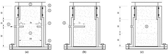
Figure 1.
Model tests for the asphalt specimen with (a) ring crack, (b) semicircle crack, and (c) air porosity of 8.0% under vertical displacement restraint conditions: ① asphalt specimen; ② ring crack; ③ pressure water; ④ glue binding; ⑤ steel sleeve; ⑥ rubber ring; ⑦ force sensor; ⑧ semicircle crack; ⑨ middle layer with large air porosity.
Observations show that the temperatures in the asphalt cores inside embankment dams in the world are mostly in the range of 5–20 °C. Accordingly, the temperatures of 5 °C and 20 °C were selected for the tests. The bottom of the specimens was glued to the bottom of the steel mould (number 4 in Figure 1). The top 60 mm of the specimens was held by the steel sleeve, and the gap between the steel sleeve and the top of the steel mould was sealed with two rubble rings (number 6 in Figure 1). The side friction of the two rubble rings was calibrated, and the sliding friction force was to be about 80 N. Water pressure was increased step by step at 200 kPa per 0.5 h. The induced vertical force P at the specimen top was measured by the force sensor. The induced average vertical stress at the top of the specimen was the value of the measured vertical force P divided by the cross section area of the specimen with a diameter of 100 mm. Figure 2 shows the curves of applying water pressure and induced average vertical stress on the specimens with different ring crack depths versus time at 5 °C and 20 °C, respectively.
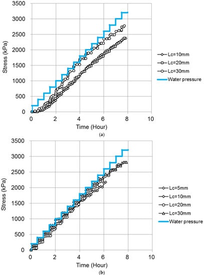
Figure 2.
Curves of applying water pressure (200 kPa per 0.5 h) and induced average vertical stress at the top of the specimens with different ring crack depths vs. time at (a) 5 °C and (b) 20 °C, respectively.
Figure 2 shows that the relationship of the water pressure versus time was lineal with a regular “saw thorn” shape. The increase of 200 kPa of water pressure for each step loading was applied in a few seconds and then kept constant for half an hour. The specimen was subjected to 200 kPa of water pressure, which was quickly applied and was kept for half an hour in each step loading. Asphalt concrete is a viscoelastic plastic material, and its behaviour is significantly time dependent and temperature dependent [20,21,22,23]. The induced average vertical stress was smaller than the water pressure . The stress was quickly increased and subsequently slowly increased with time thanks to the creep effect and stress redistributing in the asphalt concrete. That caused the “saw thorn” shape of the curve of the , which was not as regular as that of the . Before the was increased up to 600 kPa, the at 5 °C was insignificant and much smaller than that at 20 °C. Both the horizontal water pressure on the asphalt concrete and the vertical water pressure in the cracks in the asphalt concrete caused less stress at 5 °C than that at 20 °C as the asphalt concrete was harder at 5 °C than that at 20 °C.
In order to further investigate the effect of the water pressure on the behaviour of the asphalt specimen with different ring crack depths, the average vertical stress of the middle part of the specimen in the crack plane was calculated, by using Equation (1) (refer to Figure 1a):
where
- = average vertical stress of the asphalt specimen in the crack plane, kPa;
- P = induced vertical force at the top of specimen, kN;
- = applied water pressure, kPa;
- = area of the ring crack, or , mm2;
- = ring crack depth, = 5, 10, 20, and 30 m, respectively, in this study;
- = diameter of the specimen in the crack plane, mm;
- = area of the asphalt specimen in the crack plane, , mm2.
The calculated average vertical stresses at 5 °C and 20 °C under water pressure are shown in Figure 3.
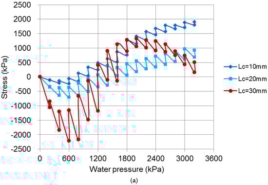
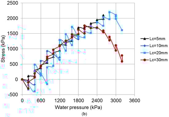
Figure 3.
Calculated average vertical stresses of the asphalt specimens in the crack plane versus water pressure for the specimens with different ring crack depths under vertical displacement restraint conditions at (a) 5 °C and (b) 20 °C, respectively. Positive stress means compressive stress.
The behaviour of the specimens with cracks can be divided into three stages with increasing water pressure. In the first stage, before the water pressure was up to 1200 kPa, was the tensile stress (Figure 3a). That was because the vertical stress (splitting) in Sm, caused by the vertical water pressure in Sc, was larger than the vertical compressive (extensional) stress in Sm, caused by the horizontal water pressure on the specimen. The “saw thorn” shape of the curves was more significant in the tension than that in the compression for the specimen with a crack depth of 30 mm because the viscoelastic plastic behaviour is more sensible in tension [24]. When the water pressure was quickly increased to 600 kPa or 800 kPa, the maximum tensile stresses were about 350, 700, and 2200 kPa for the specimens with crack depths of 10, 20, 30 mm, respectively. The tensile stresses would cause the cracks to open. If the asphalt specimens were very long and thus there was high compression (shortening) in the material above and beneath the crack, significant water pressure would fracture the asphalt specimens. In the second stage, when the water pressure was increased from 1200 kPa to 2200 kPa, turned into compressive stresses from tensile stresses and were increased with the increase in water pressure. The opened cracks would be close. In the third stage, when the water pressure increased from 2200 kPa to 3200 kPa, the compressive stress was increased but the increasing rate was reduced for the specimens with crack depths of 10 and 20 mm. However, the compressive stress was significantly reduced for the specimen with a crack depth of 30 mm, which relieved the compression of the closed crack. In general, the behaviour of the cracks in the specimens would experience an “open–close” progress.
Figure 3b shows similar curves for the stress versus water pressure to those in Figure 3a. However, the first stage was not obvious, in that the asphalt concrete is softer at 20 °C than at 5 °C. When the water pressure was quickly increased to 200 kPa or 400 kPa, the maximum vertical tensile stresses were about 350 kPa for the specimens with crack depths of 20 and 30 mm. The tensile stresses would cause the cracks to open. In the second stage, when the water pressure was increased from 400 kPa to 2400 kPa, turned into compressive stresses from tensile stresses and were increased with the increase in water pressure. In the third stage, when the water pressure increased from 2600 kPa to 3200 kPa, the compressive stresses were significantly reduced for the specimens with crack depths of 20 and 30 mm, which relieved the compression of the closed crack.
Most of asphalt cores in dams are subjected to only upstream reservoir water pressure, and water may permeate the possible cracks in the upstream face of the core. To model that condition, a semicircle crack in the specimen was produced, which is shown in Figure 1b. The test procedure was exactly the same as that in Figure 1a. The test results of two specimens (1, 2) are shown in Figure 4.
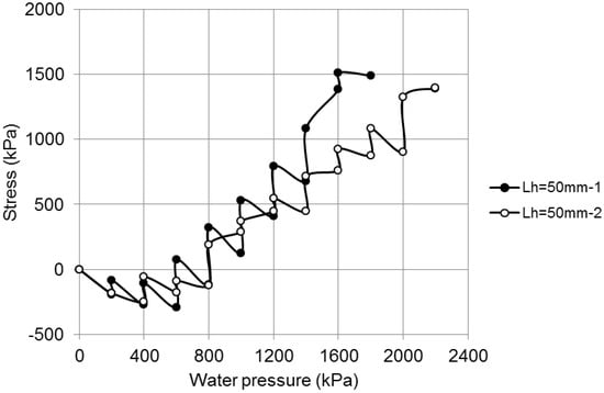
Figure 4.
Induced average vertical stress of the semicircle crack specimen in the crack plane versus water pressure under the vertical displacement restraint conditions at 20 °C.
Before the water pressure was up to about 800 kPa, the vertical stresses of the asphalt concrete in the crack plane were tensile stresses. The specimen with a semicircle crack at 20 °C was fractured when the water pressure was about 1800 kPa. The specimen was subjected to bending because of the unsymmetrical water pressure on the specimen (Figure 1b), and the local tensile strains in the zone close to the front end of the crack could exceed the allowable tensile strain of the asphalt concrete.
In order to investigate the effect of water pressure on the behaviour of the asphalt specimen with a large air porosity, model tests (Figure 1c) were carried out on the specimen with an air porosity of 8.0% in the middle part of the specimen at 5 °C and 20 °C, respectively. The test procedure was exactly the same as that in Figure 1a,b. The test results of two specimens (1, 2), one at 5 °C and the other at 20 °C, are shown in Figure 5.
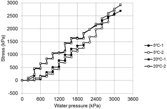
Figure 5.
Induced average stress versus water pressure for the asphalt specimen with air porosity of 8.0% in the middle part under the vertical displacement restraint conditions at 5 °C and 20 °C, respectively.
The specimen with an air porosity of 8.0% in the middle part of the specimen was not fractured at 5 °C or 20 °C when the water pressure was up to 3200 kPa. Figure 5 shows that the induced vertical stress of the specimen at 20 °C was larger than that of the specimen at 5 °C thanks to the softer behaviour at 20 °C. The specimens were not fractured as the top of the specimens were restrained to prevent the specimen from vertical displacing, and even some of the voids in the specimens were permeated with the water pressure of 3200 kPa. The high pore water pressure in the asphalt concrete was under balance conditions and could not fracture the asphalt concrete.
3.2. Model Test Results under the Unrestraint Conditions
The model test here was similar to the model test in Section 3.1, except that the top of the specimens was set to be free. The upward displacement at the centre of the specimen top was measured while applying water pressure. The test was run in a step loading creep manner, and the water pressure was increased every 2 days.
The model test was actually a short-term extension creep test. The specimens with and without cracks were tested. The extensional strain was calculated on the basis of the measured top displacement of the specimen, and the height of specimen for the calculation was taken to be 120 mm. The test results are shown in Figure 6.
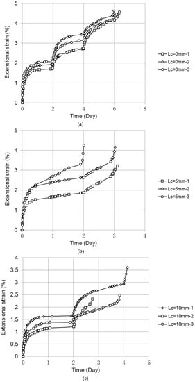
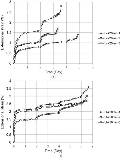
Figure 6.
Extensional strain vs. time for the specimen with different crack depths at 20 °C by applying various step creep loadings, step loading every 2 days. (a) Water pressure: 100–150–200 kPa; (b) Water pressure: 100–120–140 kPa; (c) Water pressure: 100–120–140 kPa; (d) Water pressure: 60–80–100 kPa; (e) Water pressure: 60–80–100 kPa.
Figure 6 shows that the asphalt specimens with different crack depths could be fractured in extension by applying a water pressure of 80–200 kPa over a few days at 20 °C. The water pressure in the crack could cause the local tensile strain in the crack plane of the asphalt specimen to exceed the allowable strain of the asphalt concrete and fracture the asphalt specimen. The extensional strain at failure is defined as the inflection point from the steady creep strain increase to the sharp increase. The extensional strains at failure for the specimens with different crack depths are compared and shown in Figure 7.
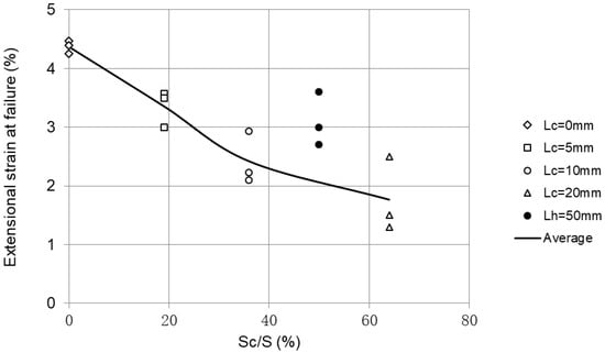
Figure 7.
Extensional strain at fracture vs. percentage of area of crack in the specimen by applying water pressure at 20 °C.
Figure 7 shows that the area of the crack in the specimen significantly reduced the extensional strain at failure. When the percentage of the crack area was 19%, 36%, and 64%, respectively, the extensional strains at failure were reduced by about 20%, 50%, and 60%, respectively, compared with that of the specimens without cracks. The extensional strain at failure (dark spots in Figure 7) was reduced by about 30%, though the semicircle cracked area was 50%. That was smaller than the estimated extensional strain at failure of about 55% for the specimen with ring cracks. The specimen with a semicircle crack underwent bending because the bending strain at failure was larger than the tensile strain at failure for the asphalt concrete [12].
The model test results for the specimens with different air porosities are shown in Figure 8.
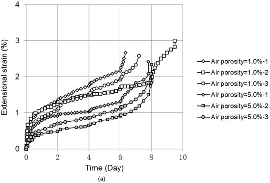
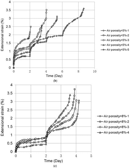
Figure 8.
Extensional strain vs. time for the specimens with different air porosities in the middle part of the specimens at 5 °C and at 20 °C by applying various step creep loading, step loading every 2 days. (a) 5 °C, water pressure: 160–180–200–220–240 kPa; (b) 20 °C, water pressure: 60–80–100–120–140–160 kPa; (c) 20 °C, water pressure: 60–80–100–120–140–160 kPa.
Figure 8 shows that the asphalt specimens with different air porosities could be fractured in extension by applying various water pressures over a few days at 5 °C and 20 °C. The extensional strains at failure for the specimens with different air porosities in the middle part of the specimens are compared and shown in Figure 9.
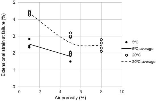
Figure 9.
Extensional strain at failure vs. air porosity in middle layer of the specimen by applying water pressure at 5 °C and 20 °C.
Figure 9 shows that the large air porosity in the middle layer of the specimen significantly reduced the extensional strain at failure. When the air porosity was 5.0%, the extensional strain at failure was reduced by about 30% at 5 °C when compared with that of the specimens with an air porosity of 1.0%. When the air porosity was 5.0% and 8.0%, the extensional strain at failure was reduced by about 40% at 20 °C.
4. Numerical Back Analysis of Model Test Results
Figure 1b showed the model test structure for asphalt concrete with a crack under the vertical displacement restraint conditions. The finite element analysis in the study was performed on the asphalt specimens with cracks under the vertical displacement unrestraint conditions. The model is axisymmetric, and the boundary conditions were simulated (see Figure 10).
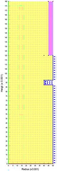
Figure 10.
Finite element mesh of the axisymmetric test model with ring crack under the vertical displacement unrestraint conditions. Yellow represents asphalt concrete, while pink represents the steel sleeve. (Unit: m).
The test model was assumed to be linear elastic when applying the software SIGMA/W in GeoStudio 2021.3. The asphalt specimens with ring cracks in the model tests were subjected to extension. Small step creep water pressure of less than 200 kPa over a few days would cause the asphalt specimens to fail (Figure 6). The Poisson’s ratio was assumed to be 0.1; that is the lowest Poisson’s ratio in the software. The average equivalent Young’s modulus at 20 °C was equal to 0.63 MPa according to the numerical back analyses of the measured average extensional strain of 4.4% for the specimens without cracks (Lc = 0 mm) by applying a water pressure of 200 kPa (see Figure 6a and Figure 7).
The test results in Figure 6a–d was back-calculated by the finite element analysis. The calculated results are shown in Figure 11.
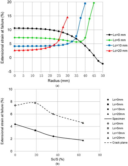
Figure 11.
Extensional strains at failure of the asphalt specimens with different ring crack depths under the vertical displacement unrestraint conditions by applying step creep water pressure at 20 °C. (a) Extensional strains in the crack plane at failure; (b) Comparison of average extensional strains at failure of the specimens and in the crack plane.
Figure 11a shows that the calculated extensional strains for the specimens without cracks at failure were about 10% in the centre, and the compressive strain was about 2.0% near the circumference. The extensional strains in the centre were reduced to about 7.0%, 4.0%, and 3.0% but up to 15–20% in the crack front area for the specimens with crack depths of 5 mm, 10 mm, and 20 mm, respectively. It is obvious that fractures in the specimens with cracks started from the cracks.
Figure 11b shows that the calculated average extensional strains at failure in the crack plane were about double that of the average extensional strains over the specimen height of 120 mm. The bottom fixing (bonding) and horizontally fixing of the top 60 mm layer (steel sleeve) of the specimen restrained the specimen to even deform over the height and thus reduced the average extensional strains at failure (see Figure 1).
The Young’s modulus at 5 °C was 1.1 MPa according to the numerical back analyses of the measured average extensional strain of 2.5% for the specimens without cracks (Lc = 0 mm, air porosity of 1.0%) by applying a water pressure of 200 kPa (see Figure 8a). The calculated extensional strains at failure of the specimen without cracks were about 6% in the centre, and the average value was 4.2%.
5. Discussions of Hydraulic Fracturing for Asphalt Cores and Earth Cores in Embankment Dams
An asphalt core is a slender impervious wall with a width of 0.5–1.2 m in an embankment dam. It has to follow the deformations imposed by the embankment and foundation during construction, reservoir impounding, and (occasionally) earthquake shaking, without significantly losing watertightness. For impervious asphalt concrete without large strains, even when water pressure up to 7.5 MPa or 11.5 MPa was acting on the asphalt concrete, no hydraulic fracturing would take place [1,2]. It was stated in ICOLD Bulletin 84 [1], “As, in comparison with earth cores, the main prerequisites are non-existent in the case of asphaltic concrete, a similar effect to hydraulic fracture can be excluded in this instance. The result of these investigations and considerations also concurs with the behaviour of asphaltic concrete facings where there has been no indication of a hydraulic fracture as yet, although there are considerably lower effective stresses in the asphaltic concrete layer of a few centimetres in comparison to the external water pressure”. However, when some cracks and/or large voids exist in the asphalt core caused by either severe earthquake shaking, large differential settlements during construction and operation, or poor construction quality, hydraulic fracturing might take place.
If an asphalt core with deep cracks is significantly arched by stiff transition zones and rockfills in a narrow valley or a deep narrow trench, the displacements of the core are significantly restrained. The model test results under the vertical displacement restraint conditions suggested that low water pressure may trigger a fracturing through the deep cracks in the core. This may explain why no significant excess pore water pressure was needed to trigger fracturing in the earth core even though the tensile strains that cracked the compacted earth materials were 10 or 100 times less than those for asphalt concrete [25,26,27].
In such a case, the asphalt core should be designed to be more flexible to reduce tensile stresses in front of the cracks. This is also meaningful for earth cores in dams. The reservoir impounding level has to be slowly raised to obtain a balance of pore water pressure in the earth core. Otherwise, hydraulic fracturing or “punch through” will occur in the earth core.
If large differential settlements between the upstream side and the downstream face of the asphalt core is predicted, the asphalt core has to be widened and made flexible to reduce the possibility of having cracks or dilations occur in the face layer of the core.
The model test and numerical back analysis results for the asphalt specimens under the vertical displacement unrestraint conditions document that low water pressure through cracks can cause the asphalt concrete to fail. The water pressure caused large tensile strains in the crack front area and made it fail. The fracturing of the asphalt specimen was due to large tensile strains. This is in agreement with the findings in the literature [28].
The calculated extensional strains at failure in the centre part of the specimens were about 6% at 5 °C and about 10% at 20 °C, respectively. The direct tensile strains at failure were about 1.5–4.0% in the temperature range of 5–20 °C [12,23,24,29]. The extensional strains at failure were about two to four times that of the direct tensile strains at failure for the asphalt concrete materials.
Air porosities of 5% and 8% for the asphalt concrete significantly reduced the extensional strains at failure compared with that of the asphalt concrete with an air porosity of 1.0% (Figure 11). Pore water pressure in many of the voids distorted the asphalt concrete and caused cracks in the asphalt concrete, which contributed to the reduction in extensional strains at failure. In practice, an asphalt core with an air porosity of about 8.0% is extremely impossible to occur as such a big air porosity for the asphalt layer is very easily detected in the field during construction. An air porosity of about 5.0% is also easily detected during construction by an experienced working team in the field. An air porosity of 3.0–4.0% for the asphalt layer is difficult to detect in the field. If that happens and is detected, the layers must be removed according to the specifications [4,5,30]. In common practices, a specialty contractor is preferable for performing the asphalt core job on embankment dams.
The bitumen content of mineral weight for the asphalt concrete was 6.5% in the study. In modern asphalt core dams, the bitumen content is about 7.0%, and the core is at least 60 cm wide. That significantly reduces the possibility of cracks and having an air porosity of larger than 3.0%. Field observations and long-term creep test results in the laboratory showed that the initial air porosity of asphalt concrete was reduced by about 50% [27]. Should cracks occur in the asphalt core, the viscoelastic plastic and ductile properties of asphalt concrete will provide a self-healing ability over time, under the loading of overlying embankment, and at favourable temperatures inside the dams [4,11].
6. Summary and Conclusions
Cylindrical test models were developed to investigate the possibility of hydraulic fracturing when the asphalt core in dams had cracks or a large air porosity. The model tests were conducted under restraint and unrestraint conditions at 5 °C and 20 °C. Water pressure was applied to the asphalt models in a step loading manner: 0.5 h per step or 2 days per step. The model test results for the asphalt specimens with ring cracks under the unrestraint conditions were back-analysed by applying finite element method. According to the model test results and the numerical back analysis results, the following conclusions are provided:
- When asphalt concrete with cracks was under vertical restraint conditions, the cracks could experience an “open–close” progress with increasing water pressure. This suggested that if the asphalt concrete were long, low water pressure would trigger a fracturing through the cracks.
- When asphalt concrete with cracks was under vertical unrestraint conditions, low water pressure could cause the asphalt concrete to fail. The magnitude of the extensional strains at failure was significantly reduced by the cracked areas (crack depths).
- When the asphalt specimens with a large porosity were under vertical unrestraint conditions, low water pressure could cause the asphalt specimens to fail. The magnitude of the extensional strains at failure was significantly reduced by the large air porosity.
- When asphalt concrete with cracks was under vertical restraint conditions, high tensile stresses in the cracks were caused at 5 °C, while insignificant tensile stresses were caused at 20 °C by applying water pressure in the initial phase. When the asphalt specimens were under vertical unrestraint conditions, the extensional strains at failure at 5 °C were 20–50% smaller than those at 20 °C.
On the basis of the discussions and the above conclusions, the following suggestions are provided for the design of an asphalt core in an embankment dam:
- When an asphalt core embankment dam is located in a narrow valley or a deep narrow trench, the bottom of the asphalt core should be widened and the slopes of the trench should be gentle to avoid having the core be significantly arched by the rockfills.
- If large differential settlements between the upstream and downstream faces of the core are predicted, possibly due to deep compressive foundations, and/or the dam if is located in a very seismic region, the asphalt core should be widened and be more flexible to avoid or reduce cracks or dilations in the faces of the core.
- An asphalt core is a slender impervious wall in a dam, and its construction quality must be ensured. A specialty contractor is preferable for performing the asphalt core job, to rule out a possible weak bond between the layers and to ensure that there is an air porosity larger than 3.0% in the core.
Author Contributions
Conceptualization, W.W.; methodology, W.W.; software, Y.Z. (Yue Zhu); validation, Y.Z. (Yue Zhu) and S.F.; formal analysis, W.W.; investigation, Y.Z. (Yue Zhu) and S.F.; resources, Y.Z. (Yingbo Zhang); data curation, Y.Z. (Yue Zhu); writing—original draft preparation, W.W.; writing-review and editing, W.W.; visualization, Y.Z. (Yue Zhu); supervision, Y.Z. (Yingbo Zhang); project administration, Y.Z. (Yingbo Zhang); funding acquisition, Y.Z. (Yingbo Zhang). All authors have read and agreed to the published version of the manuscript.
Funding
The research work for the paper was supported by the National Natural Science Foundation of China (no. 52039008).
Institutional Review Board Statement
Not applicable.
Informed Consent Statement
Not applicable.
Data Availability Statement
Not applicable.
Acknowledgments
The authors appreciate the assistance of Mengyue Shi during the experimental work.
Conflicts of Interest
The authors declare no conflict of interest.
References
- ICOLD. Bituminous Cores for Fill Dams; Bulletin 84; International Commission on Large Dams: Paris, France, 1992. [Google Scholar]
- Schönian, E. The Shell Bitumen Hydraulic Engineering Handbook; Shell International Petroleum Company Ltd.: London, UK, 1999. [Google Scholar]
- Ghanbari, A.; Rad, S. Development of an empirical criterion for predicting the hydraulic fracturing in the core of earth dams. Acta Geotech. 2015, 10, 243–254. [Google Scholar] [CrossRef]
- ICOLD. Asphalt Cores for Embankment Dams; Bulletin 179; International Commission on Large Dams: Paris, France, 2022. [Google Scholar]
- People’s Republic of China National Energy Administration. Standard DL/T 5363-2016; Specifications for Construction of Hydraulic Rolled Bituminous Concrete. China Water and Power Press: Beijing, China, 2016. (In Chinese)
- Feizi-Khankandi, S.; Ghalandarzadeh, A.; Mirghasemi, A.; Höeg, K. Seismic analysis of the Garmrood embankment dam with asphaltic concrete core. Soils Found. 2009, 49, 153–166. [Google Scholar] [CrossRef]
- Baziar, M.; Salemi, S.; Merrifield, C. Dynamic centrifuge model tests on asphalt-concrete core dams. Géotechnique 2009, 59, 763–771. [Google Scholar] [CrossRef]
- Jiao, Y.; Ren, G.; Peng, W.; Gu, X.; Wang, N. Aseismic measures for asphalt concrete core dams by dynamic centrifuge modelling tests. Chin. J. Geotech. Eng. 2020, 42 (Suppl. S1), 167–171. [Google Scholar]
- Ghanooni, M.; Roosta, R. Seismic analysis and design of asphaltic concrete core embankment dams. Int. J. Hydropower Dams 2002, 9, 75–78. [Google Scholar]
- Valstad, T.; Selnes, P.; Nadim, F.; Aspen, B. Seismic response of a rockfill dam with an asphaltic concrete core. Water Power Dam Constr. 1991, 4, 22–27. [Google Scholar]
- Saxegaard, H. Crack self-healing properties of asphalt concrete: Laboratory simulation. Hydropower Dams 2003, 3, 106–109. [Google Scholar]
- Zhang, Y.; Höeg, K.; Wang, W.; Zhu, Y. Watertightness, cracking-resistance and self-healing of asphalt concrete used as a water barrier in dams. Can. Geotech. J. 2013, 50, 275–287. [Google Scholar] [CrossRef]
- Innerhofer, G.; Tschernutter, P.; Kainrath, A. Behaviour of Asphalt Concrete Core Embankment Dams (ACED) and Shear Zone Development, Twenty-Sixth International Congress on Large Dams; ICOLD Press: Vienna, Austria, 2018; pp. 1349–1361. [Google Scholar]
- Pircher, W.; Schwab, H. Design, Construction and Behaviour of the Asphaltic Concrete Core Wall of the Finstertal Dam, R.49–Q.61, Transactions, 16th International Congress on Large Dams; ICOLD Press: Paris, France, 1988; pp. 901–924. [Google Scholar]
- Rao, X.; Gong, B.; Ding, H.; Zhou, W.L. Experimental study on hydraulic concrete splitting of asphalt concrete, Practice and Development of Geotechnical Testing Technology. In Proceedings of the 24th National Geotechnical Testing Symposium, Zhengzhou, China, 13 October 2005; pp. 141–145. [Google Scholar]
- Wang, Z.; Hao, J.; Yang, J.; Cao, Y.; Li, X.; Liu, S. Experimental study on hydraulic fracturing of high asphalt concrete core rock-fill dam. Appl. Sci. 2019, 9, 2285. [Google Scholar] [CrossRef]
- People’s Republic of China National Energy Administration. Standard DL/T 5362-2018; Test Code for Hydraulic Bitumen Concrete, State Power Industry. China Electric Power Press: Beijing, China, 2018. (In Chinese)
- Li, Q.; Wang, Y.; Wang, F.; Li, Q.; Forson, K.; Bai, H.; Yuan, L. Effect of a modified silicone as a thickener on rheology of liquid CO2 and its fracturing capacity. Polymers 2019, 11, 540. [Google Scholar] [CrossRef] [PubMed]
- Li, Q.; Wang, F.; Forson, K.; Zhang, J.; Zhang, C.; Chen, J.; Xu, N.; Wang, Y. Affecting analysis of the rheological characteristic and reservoir damage of CO2 fracturing fluid in low permeability shale reservoir. Environ. Sci. Pollut. Res. 2022, 29, 37815–37826. [Google Scholar] [CrossRef]
- Wang, W.; Hu, K.; Feng, S.; Li, G.; Höeg, K. Shear behavior of hydraulic asphalt concrete at different temperatures and strain rates. Constr. Build. Mater. 2020, 230, 117022. [Google Scholar] [CrossRef]
- Feng, S.; Wang, W.; Hu, K.; Höeg, K. Stress-strain-strength behavior of asphalt core in embankment dams during construction. Constr. Build. Mater. 2020, 259, 119706. [Google Scholar] [CrossRef]
- Ning, Z.; Liu, Y.; Wang, W. Compressive behavior of hydraulic asphalt concrete under different temperatures and strain rates. J. Mater. Civil Eng. 2021, 33, 04021013. [Google Scholar] [CrossRef]
- Zhang, Y.; Zhu, Y.; Wang, W.; Ning, Z.; Feng, S.; Höeg, K. Compressive and tensile stress-strain-strength behavior of asphalt concrete at different temperatures and strain rates. Constr. Build. Mater. 2021, 311, 125362. [Google Scholar] [CrossRef]
- Ning, Z.; Liu, Y.; Wang, W.; Dong, J.; Meng, X. Experimental study on effect of temperature on direct tensile behavior of hydraulic asphalt concrete at different strain rates. J. Mater. Civ. Eng. 2022, 34, 04022143. [Google Scholar] [CrossRef]
- Sherard, J. Hydraulic fracturing in embankment dams. J. Geotech. Eng. ASCE 1986, 10, 905–927. [Google Scholar] [CrossRef]
- Zhang, B.; Li, N.; Li, Q.; Sun, X. Mechanism analysis and model test of hydraulic fracturing in embankment dams. Chin. J. Geotech. Eng. 2005, 11, 1277–1281. [Google Scholar]
- Leonards, G.; Narain, J. Flexibility of clay and cracking of earth dams. J. Soil Mech. Found. Div. (ASCE) 1963, 89, 47–98. [Google Scholar] [CrossRef]
- Zhang, Y.; Wang, W.; Zhu, Y. Investigation on conditions of hydraulic fracturing for asphalt concrete used as impervious core in dams. Constr. Build. Mater. 2013, 50, 275–287. [Google Scholar] [CrossRef]
- Wang, W. Research on the Suitability of Asphalt Concrete as Water Barrier in Dams and Dikes. Ph.D. Thesis, University of Oslo, Oslo, Norway, 2008. [Google Scholar]
- People’s Republic of China National Energy Administration. Standard NB/T 11015-2022; Code for Design of Asphalt Concrete Facings and Cores for Embankment Dams. China Water and Power Press: Beijing, China, 2022. (In Chinese)


Disclaimer/Publisher’s Note: The statements, opinions and data contained in all publications are solely those of the individual author(s) and contributor(s) and not of MDPI and/or the editor(s). MDPI and/or the editor(s) disclaim responsibility for any injury to people or property resulting from any ideas, methods, instructions or products referred to in the content. |
© 2023 by the authors. Licensee MDPI, Basel, Switzerland. This article is an open access article distributed under the terms and conditions of the Creative Commons Attribution (CC BY) license (https://creativecommons.org/licenses/by/4.0/).