Abstract
Technological advancements have revolutionized the space industry, facilitating deep space exploration using CubeSats. One objective is to locate potential life-support elements, such as water, on extraterrestrial planets. Water possesses a distinct spectral signature at 183 GHz, useful in remote sensing and environmental monitoring applications. Detecting this signature provides crucial information about water and ice presence and distribution on celestial bodies, aiding future exploration and colonization efforts. Mostly in space remote sensing uses corrugated horn antennae due to high gain and radiation patterns but fabrication of corrugated antenna is very challenging or even impossible in some cases. To ease this challenge, in our research we propose ideas to transform a corrugated horn antenna into a smooth-walled design by using MATLAB Cubic smoothing Splines algorithms. We compare simulation results between smooth-walled and corrugated antennas, and we can see some improvements in insertion losses, Voltage Standing Wave ratio (VSWR), and gain. We also manufactured this 183 GHz antenna using a commercially available 3D printer by utilizing Acrylonitrile Butadiene Styrene (ABS) material. The antenna surface was then coated with a thin layer of copper using conductive paint. In the end, we practically evaluate smooth-walled antenna functionality and compare it with the theriacal results. Validating the antenna’s functionality proposes a cost-effective and accessible production method to be used in a CubeSat engineering model or university students’ project.
1. Introduction
The enhancement of high-resolution scientific spectroscopic THz remote sensing is extensively spreading throughout the universe due to the ESA (European Space Agency) cornerstone Herschel Space Observatory [1]. Recently, THz and submillimeter technology have been widely used in remote sensing imaging. They offer unique advantages in detecting various materials and identifying their properties [2,3], elements detection, and outer space exploration. A high-gain antenna in the THz frequency range is important to enhance the link budget and THz signal observing capabilities [4]. THz circuits have the potential for space-based communication systems with high data transmission rates and metal packaging can help to dissipate heat and reduce parasitic capacitances/inductances [5], and mini-sized THz horn antenna has a simple structure and provides better directivity and radiation efficiency. Horn antennas have been extensively utilized in various applications due to their myriad of beneficial properties. These antennas are known for their broadband performance, making them suitable for a broad range of frequencies, which is particularly advantageous for systems that need to receive or transmit signals over a variety of frequency bands [6]. Further enhancing their efficiency, horn antennas exhibit high directivity and gain. This characteristic allows them to focus radio waves effectively in a specific direction, thereby improving transmission and reception efficiency, especially over long distances [7]. The advantageous low Voltage Standing Wave Ratio (VSWR) of horn antennas ensures efficient power transfer and minimizes signal loss due to reflections at the antenna–feed line interface [8]. Their robustness and reliability further add to their appeal, making them less sensitive to weather conditions than some other types of antennas. This advantage, coupled with their simple construction, contributes to their durability and reliability [9]. Another significant advantage of horn antennas lies in their ease of fabrication and design. Their relatively simple structure makes them not only easy to design and manufacture but also allows for customization to meet specific requirements [10]. Moreover, horn antennas are less prone to interference from other sources due to their high directivity. This makes them especially suitable for environments with high levels of electromagnetic noise [11]. Horn antennas demonstrate excellent compatibility, are able to be readily used with other microwave components such as waveguides and coaxial lines [12]. These advantages make it a promising candidate for THz communication systems [13]. For many years, corrugated horn antennas have been examined as antenna feeds, and due to technological development, it has become possible to fabricate [14,15]. Outer space missions require high-quality factor subsystems. Utilizing deployable antenna mechanisms escalates the risk of a satellite malfunctioning, subsequently, satellite engineers focus on non-deployable antennas such as horns, patches, etc. In the THz range, the wavelength is miniature; therefore, manufacturing a patch antenna via current technology is impossible; therefore, horn antennas are logical choices [16]. Meteorology microsatellites to monitor atmosphere climate changes usually use a horn antenna feeder Corrugated horn antennas offer several benefits for CubeSat remote sensing applications. They have a high directivity and gain, which makes them suitable for long-range communication and remote sensing. Corrugations in the horn structure improve the antenna’s impedance matching and reduce standing waves, which leads to better performance at higher frequencies. The use of corrugated horns can reduce unwanted side lobes and cross-polarization, which can improve the antenna’s performance in space-based remote sensing applications [17]. The corrugated horn antenna fulfills all of the required remote sensing specifications [18,19,20]. Over the past 50 years, corrugated horn antennas have been well collected as feeds for reflector antennas [21]. The diverse capabilities of corrugated horn antennas make them a valuable tool in remote sensing applications, particularly in space [22]. Their ability to operate over a wide frequency range and their superior performance characteristics make them highly desirable for the development of remote sensing instruments [23,24].
At these frequencies, the size of the antenna becomes very small and fabrication tolerances become very tight. As a result, even minor variations in the fabrication process can cause significant malfunctioning in the antenna [25]. Hence, simpler horn antennas are preferred in CubeSat remote sensing applications due to their enhanced gain, directivity, and ease of manufacturability. Such antennas have been used in planetary water detection missions, including the 183 GHz smooth-walled corrugated horn antenna designed for a CubeSat THz spectrometer payload [26,27]. Horn antennas play a key role in reflectometry systems. There are several horn antenna options available for quasi-optic systems, but among them, the corrugated horn antenna fulfills the requirements for reflectometry systems [28]. Establishing high-frequency antennas presents unique challenges [29]. To overcome these, we initiate our process by creating a model of the corrugated horn antenna in MATLAB, followed by a simulation of the antenna using CST software, from which we obtain initial simulation results. These results then undergo a smoothing process, as we input the corrugated horn antenna’s (x, y) data into MATLAB’s smooth spline curve fitting tool, thereby transforming the corrugated data into a smooth-walled format. This approach provides the data necessary to transition from a corrugated to a smooth-walled horn antenna design. Simulation results of the smooth-walled horn antenna demonstrate that applying the smooth spline algorithm enhances antenna gain and directivity, improves side lobe bands, and expands bandwidth.
In the end, we successfully manufactured a smooth-walled horn antenna using a 3D printer and ABS plastic material. We thoroughly evaluated the functionality of the fabricated antenna, including and VSWR results. This cost-effective method offers viable options for employing the antenna on CubeSat engineering models or primary models, effectively demonstrating the functionality of the mission and payload. Moreover, this approach proves invaluable for university student projects, enabling them to assess their designs at an affordable price and explore concepts related to magnetic fields.
Our plan is to integrate this antenna into a 3-Unit CubeSat platform, which will also include a THz subharmonic mixer-spectrometer. The mission will orbit the moon to determine the presence of ice water. The integrated system is designed to capture the moon’s surface spectrum in the 160 GHz–200 GHz frequency range, thus enabling the detection of water spectral signatures and the identification of ice water locations on the moon’s surface [29].
This paper introduces our methodology and theoretical concept, beginning with an explanation of the corrugated horn antenna formula. Subsequently, we demonstrate the transformation of this corrugated design into a smooth-walled antenna using MATLAB’s spline curve fitting algorithm. The simulation of both antennas is presented, comparing the results and revealing that, within an equivalent waveguide, aperture, and horn length, we achieve nearly identical magnetic behavior. Next, we proceed with the fabrication of the antenna, highlighting the utility of our proposed design in CubeSat remote sensing applications. By showcasing the successful implementation of our antenna in this field, we emphasize its practicality and effectiveness. This research lays the groundwork for using the smooth-walled antenna in CubeSat missions, particularly in the context of remote sensing, thereby contributing to advancements in space exploration and satellite technology experimental works.
2. Design Methodology
Stephen Hawking once said that humanity will one day be faced with a choice between extinction and outer space colonization. The concepts arising from this insightful speech suggest that space colonization is a vital investment for the long-term survival of humanity [30]. As the sun’s energy is finite, with estimates suggesting it will die out in the next 5 billion years, it is logical to begin taking preventive measures now to ensure humanity’s future [31]. To create life on an extraterrestrial planet, water is a vital element there. Electrolysis of water is a critical resource for supporting life on an uninhabited planet, as it can be used to split oxygen for breathing, hydrogen for refueling spaceship propulsion systems, and for agriculture [29]. According to current technology, human exploration beyond our solar system remains beyond our capabilities. So far, the farthest planet we have successfully reached is Mars, thanks to NASA’s landers, and the Moon, visited by NASA’s astronauts. Consequently, our options for potential human habitation in outer space are limited to Mars and the Moon.
Considering the feasibility of near-future living in outer space, we have chosen to focus on the Moon. We believe that, given the current technological advancements, establishing a human presence on the Moon is more achievable than on Mars. Therefore, directing our efforts toward lunar exploration and colonization seems to be a more practical and realistic goal.
In this paper, we propose a system for detecting water on the Moon, an essential technology to facilitate scientific exploration and potentially provide resources for future space missions. The proposed system incorporates a subharmonic mixer spectrometer payload mounted on a CubeSat, aimed at precisely detecting water particles on the lunar surface. This system builds upon our previous work detailed in [29], where we introduced the initial concept.
In this current study, we focus on optimizing the payload antenna to enhance the system’s performance. By improving the antenna’s design, we aim to achieve more accurate and efficient water detection capabilities. This research represents a significant advancement in our pursuit of harnessing space resources and contributes to the broader goal of enabling human exploration and habitation beyond Earth [32].
There are several techniques for optimizing the performance of a horn antenna. One approach is to design the horn with the correct geometrical dimensions and material properties, such as the size and shape of the aperture, the length of the horn, and the material used for the horn and the aperture. Another approach is to use matching circuits, such as impedance matching networks, to ensure that the antenna is matched to the transmission line, which can improve its efficiency and reduce reflection losses. Additionally, adjustments or modifications may be necessary to mitigate the effects of nearby structures or interference sources. The choice of frequency, polarization, and beamwidth can also impact the performance of the horn antenna, and these parameters may need to be optimized as well. In this paper, we transform the specification of the corrugated horn antenna by the usage of curve fitting algorithms. Firstly, we must plot the 183 GHz corrugated horn antenna regarding to formulas on MATLAB, then simulate the antenna in CST software. After the simulation of the corrugated antenna at CST software, we apply MATLAB spline smooth curve algorithms on corrugated horn antenna geometry and transform the corrugated horn antenna into an identical size smooth-walled horn antenna. At the end of this section, we extract the entry antenna design parameter data.
Following section, we undertake the process of smoothing and optimizing the antenna design, by taking this into account we keep antenna specifications for CubeSat remote sensing.
In the initial step of our study, we must calculate the parameters of the corrugated antenna see Figure 1. Considering the center frequency of 183 GHz, which corresponds to a wavelength of 1.6655 mm.
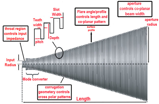
Figure 1.
Corrugated horn antenna geometrical characteristics [26].
Follows we calculate Corrugated horn antenna parameters with variable depth:
Input radius equals
Outer radius with −15 dB edge-taper gain and 20° half-cone angle [8] equals:
Slot pitch P can be chosen in the range of
Slot pitch-to-width ratio δ in the range
Length of horn antenna
Number of slots
Number of variable depth-slots
Width of the slot teeth
Figure 1 illustrates the general geometry of a corrugated horn antenna. By applying Formulas (1)–(8), we can simply calculate the required variables. When constructing the teeth of the antenna from the input radius to the aperture, the hyperbolic corrugated surface profile and slot-depth will vary based on the pitch number. Therefore, these variables must be computed as an array of numbers.
Following in Table 1, we can see the primary geometry of corrugated horn antenna. To be capable of computing number of teeth and their geometry, we apply Table 1 Information to Formulas (9)–(14).

Table 1.
Corrugated horn antenna geometric data.
To compute array antenna and , we proceed via following formulas:
To compute we must take into account then slot depth of the jth slot is
For then the slot depth of jth slot is
In Figure 2, we show the subsequence of corrugated antenna from waveguide to aperture. Next to those calculations, we proceed to plot antenna 2D sketch. From Formulas (12)–(14), we realize the coordinates of corrugated antenna teeth depend on jth of each slot. This property assists us to figure antenna shape more accurately. From to N, the scale of slots approximately stays unchanged, only gradually rises up. See Figure 2 for more clearances.
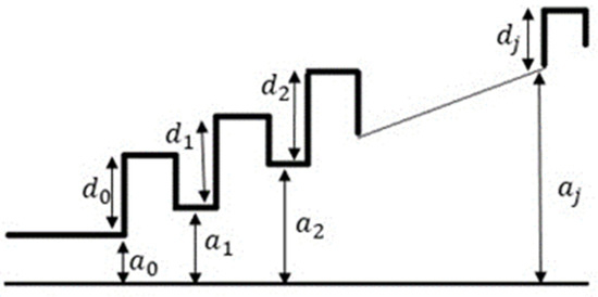
Figure 2.
Corrugated horn antenna 2D geometry.
In this section, we present the computed data that forms the foundation for designing the corrugated horn antenna. In the next section, we conduct simulations of the corrugated horn antenna and apply the smooth-walled algorithm to transform it into a smooth-walled design. Through optimization, we further refine the smooth-walled antenna to achieve enhanced performance characteristics. Finally, we provide the necessary data required for the fabrication of the smooth-walled antenna, facilitating its practical realization. This process ensures that the resulting smooth-walled antenna meets the desired specifications and delivers improved performance compared to the original corrugated design.
3. Simulation and Results
After computing the parametric data for we proceed to measure (x, y) data, which allows us to plot the corrugated horn antenna on MATLAB. Subsequently, we export the 2D data from MATLAB to CST for antenna simulation. To accomplish this, we utilize the following code lines in MATLAB:
By executing these code lines, we generate the necessary data for antenna simulation in CST, enabling us to analyze and optimize the antenna’s performance, see Figure 3:
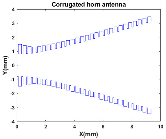
Figure 3.
Corrugated horn antenna on MATLAB plot.
We successfully exported the 2D data from MATLAB to CST software, enabling us to construct the 3D model of the corrugated horn antenna (refer to Figure 4a). The antenna’s dimensions are observed to be 9.3 mm in length and 6.28 mm in aperture, making it compact and suitable for small satellites. These specifications make the antenna a viable candidate for various missions, taking advantage of its miniature size.
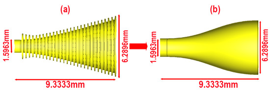
Figure 4.
3D model of (a) the corrugated horn antenna and transform to (b) smooth-walled antenna.
Once the corrugated horn antenna is illustrated, we utilize smooth spline curve fitting tools with a smooth factor of 0.4 to transform the corrugated antenna into a smooth-walled horn antenna. Fabricating corrugated horn antennas at THz frequencies can indeed be a challenging and, at times, an unfeasible task. However, our proposed solution of transforming the antenna geometry into a smooth-walled design allows us to utilize straightforward 3D printing technology for its production. This transformation not only simplifies the manufacturing process but also makes it cost effective and time saving.
By adopting the smooth-walled design, we overcome the complexities associated with traditional corrugated antennas, making it a viable option for various applications in the THz range. The utilization of 3D printing technology further enhances accessibility and affordability, making the smooth-walled antenna an attractive choice for research and experimental purposes. Our approach opens new possibilities for the development of advanced antennas in the THz domain, paving the way for more efficient and cost-effective solutions in the field of space exploration and beyond. The CAD model of the smooth-walled horn antenna on CST can be seen in Figure 4b.
In Figure 4, we present the transformation of the corrugated antenna into a smooth-walled design while maintaining identical dimensions. Through this optimization process, we have successfully achieved a seamless transition from the original corrugated configuration to the smooth-walled counterpart, all while preserving the critical antenna parameters. This transformation not only simplifies the fabrication process but also enhances the antenna’s performance, making it a promising candidate for various applications, especially in the THz frequency range.
The following figures display the comparison results of the corrugated and smooth-walled antenna simulations in CST software. Through this simulation, we gain the antenna’s performance characteristics, including , VSWR, gain, directivity, and radiation patterns.
Figure 5 showcases the simulations of both the 183 GHz corrugated horn antenna and the smooth-walled horn antenna. At the designated frequency of 183 GHz, the parameter for the corrugated horn antenna remains below −15 dB, which confirms its usability at the specified frequency. However, the parameter of the smooth-walled antenna, also at the same frequency and size, stays under −25 dB, indicating superior impedance match capability and lower insertion losses.
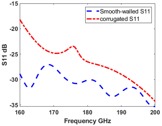
Figure 5.
Simulation of 183 GHz Corrugated Horn Antenna and Smooth-Walled Horn Antenna.
This comparison reveals the improvements achieved through the transformation to a smooth-walled design. The smooth-walled antenna’s enhanced impedance matching, and reduced insertion losses make it a more efficient and reliable choice for operating at the targeted frequency range.
Figure 6 depicts the VSWR measurements of both the corrugated horn antenna and the smooth-walled horn antenna in the same frequency range. For the corrugated horn antenna, the VSWR values range between 2.2 to 0.4, indicating some degree of impedance mismatch and signal reflections. However, the smooth-walled antenna maintains VSWR values close to 1:1 throughout the same frequency range, suggesting excellent impedance matching and minimal signal reflections. The smooth-walled antenna’s stable VSWR values make it a highly efficient and reliable option for transmitting and receiving signals in the specified frequency range, which is crucial for space exploration and remote sensing applications.
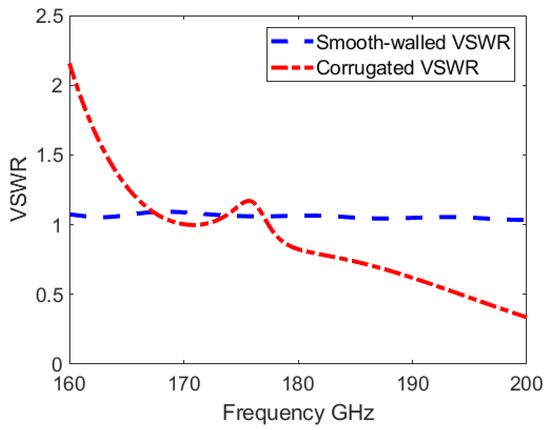
Figure 6.
VSWR (Voltage Standing Wave Ratio) comparison of corrugated horn antenna and smooth-walled horn antenna.
In Figure 7, we observe the simulated gain results of both the corrugated horn antenna and the smooth-walled horn antenna. The corrugated horn antenna exhibits a gain of 1 dB, which may pose challenges in satellite remote sensing applications due to its relatively low performance. However, by applying the smooth-walled MATLAB algorithm to the corrugated antenna, we achieve a remarkable increase in gain, reaching 18 dB. This significant enhancement in gain makes the smooth-walled antenna an ideal choice for satellite remote sensing applications, as it can overcome the challenges posed by the original corrugated design.
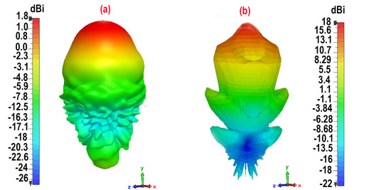
Figure 7.
Gain comparison of (a) corrugated horn antenna and (b) smooth-walled horn antenna.
Figure 7 clearly demonstrates the improved gain performance of the smooth-walled antenna compared to the corrugated horn antenna. This result validates the effectiveness of our proposed method in transforming the corrugated design into a smooth-walled configuration. Importantly, this optimization process does not compromise the antenna’s functionality; instead, it enhances its magnetic specifications, resulting in better performance. In Figure 8, we present the gain phi and gain theta results for both antennas, and it is evident that there are no unconventional or unexpected outcomes. The results are consistent and fall within acceptable ranges, demonstrating the appropriateness and effectiveness of our antenna design and optimization process. Based on appropriate simulation results, we are now ready to proceed with the fabrication of the antenna. The successful fabrication and subsequent evaluation of the antenna’s functionality will be a crucial step in validating the performance improvements achieved through the smooth-walled design.
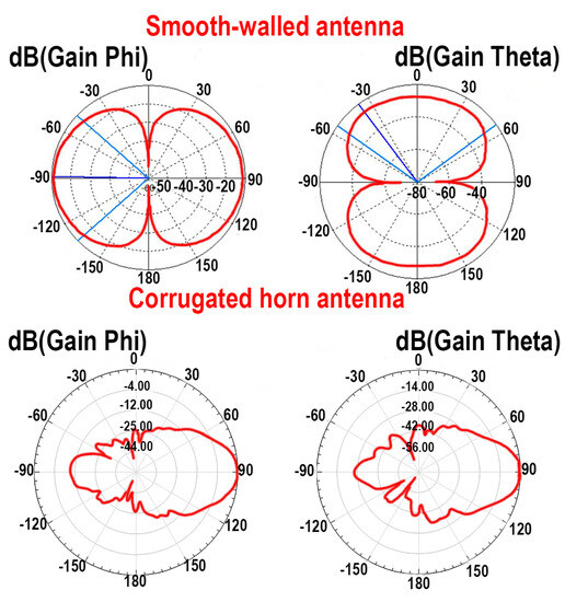
Figure 8.
2D pattern Phi and Theta gain.
4. Smooth-Walled Horn Antenna Fabrication and Practical Results
The experimental procedure commenced with the simulation of a corrugated horn antenna. Given the complex geometries associated with the corrugations, such antennas often pose fabrication challenges, particularly at THz frequencies where antenna dimensions are relatively small. To address these fabrication challenges, we employed a smooth-walled algorithm designed to simplify the structure of the corrugated antenna. The algorithm transformed the corrugated horn antenna into a smooth-walled antenna, maintaining the efficiency of wave propagation while enabling a simpler manufacturing process.
Fabrication Process
The fabrication of the horn antenna was conducted using 3D printing technology, with ABS as the material of choice. The ABS allowed for a precise yet cost-effective production of the smooth-walled antenna. Subsequent to the 3D printing process, a copper conductive thin layer was brushed on the antenna surface. This step involved brushing the antenna with the paint to provide a conductive layer, thereby enabling it to function as an antenna. In Figure 9, we show a fabricated antenna with a copper conductive surface.
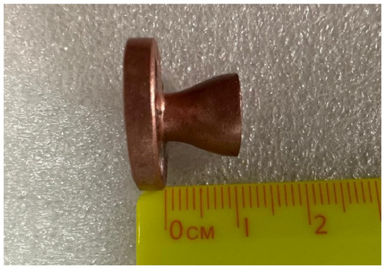
Figure 9.
Fabricated smooth-walled horn antenna.
Utilizing the facilities at the Beijing Institute of Technology, we tested the functionality of our smooth-walled antenna design. In our experimental setup, we utilize a 220 GHz multiplier and a 220 GHz mixer to down-convert signals into the frequency range of DC to 3 GHz. This enables us to evaluate the functionality of the antennas in sending and receiving data. In this configuration, one antenna functions as the transmitter, while the other acts as the receiver. As depicted in Figure 10, the transmitter antenna is connected to a receiver, which, in this case, is a 220 GHz multiplier. The multiplier multiplies the 61 GHz input signal with a 12 dB power to generate a 183 GHz signal, which is then transmitted by our smooth-walled antenna. On the receiver side, another smooth-walled antenna is connected to a 22 GHz mixer, with a 6 dB Local Oscillator signal as the entry. This setup down-converts the received signal to a 1 GHz baseband. At this stage of our experiment, our primary objective is to verify the capability of the copper-coated antenna in signal transmission. Figure 10 illustrates the presence of signals on the oscilloscope, confirming the successful transition capability of our antennas. This step serves to demonstrate that the antennas are indeed capable of transmitting and receiving signals. In the subsequent paragraph, we will present practical measurements of the antennas’ VSWR and parameters, further validating the performance of our smooth-walled antennas.
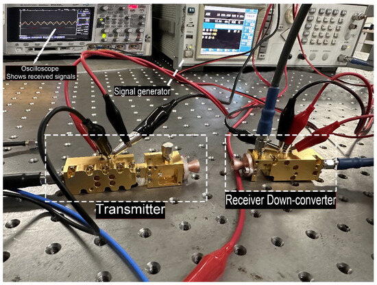
Figure 10.
Experimental setup demonstrating the transmission and reception of signals between two smooth-walled antennas.
Our primary goal is to streamline the fabrication of high-frequency corrugated horn antennas and to verify that the functionality remains consistent between the smooth-walled and corrugated horn designs. To achieve this, we utilized the advanced Keysight E5080A ENA analyzer, capable of measuring and VSWR parameters of our smooth-walled antenna with precision.
During the practical measurements, we connected the smooth-walled antenna to the Keysight E5080A ENA using suitable coaxial cables and connectors for the 183 GHz frequency range. We performed accurate calibration using a well-defined calibration kit to remove any systematic errors from the measurement setup.
Subsequently, we initiated the measurement, wherein the ENA sent a signal to the smooth-walled antenna and precisely measured the reflected signal. The obtained data represented the reflection coefficient of the antenna at various frequencies. The practical results for were presented in Figure 11, depicting the antenna’s performance in terms of impedance matching.
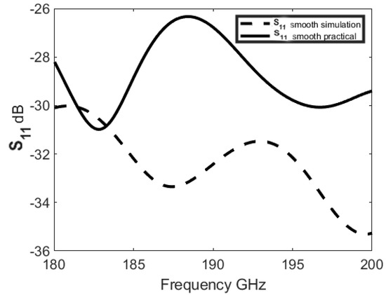
Figure 11.
Measurement results for smooth-walled antenna.
Furthermore, we conducted VSWR measurements on the same setup to assess the magnitude of impedance mismatch between the smooth-walled antenna and the transmission line. The Keysight E5080A ENA precisely calculated VSWR based on the measured data. The practical VSWR results were illustrated in Figure 12, showcasing the antenna’s impedance-matching capabilities across the operating frequency range.
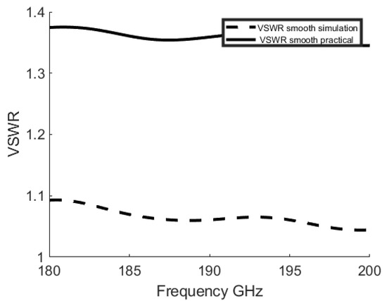
Figure 12.
VSWR measurement results for smooth-walled antenna.
By leveraging the Keysight E5080A ENA analyzer for and VSWR measurements, we validated the smooth-walled antenna’s functionality in effectively transmitting and receiving signals at 183 GHz. These practical results corroborate the performance consistency and suitability of the method for laboratory and experimental high-frequency applications. In Table 2, we present a summarized comparison of key parameters among corrugated, smooth-walled, and fabricated antennas. This comparative analysis provides strong evidence for the viability and effectiveness of our proposed method.
Table 2.
Comparison of corrugated, smooth-walled, and fabricated antenna parameters.
5. Project Benefits and Future Work
In this paper, we have successfully proposed and demonstrated a cost-effective method to transform corrugated horn antennas into smooth-walled designs. The utilization of MATLAB Cubic Smoothing Splines algorithms allowed us to achieve impressive antenna performance, including enhanced gain, reduced parameters, and improved VSWR, within the frequency range of 160 GHz to 200 GHz. We employed a commercial 3D printer with ABS material to fabricate the smooth-walled 183 GHz horn antenna, and its functionality was verified through practical experiments.
By using copper conductive paint to coat the antenna surface, we efficiently transformed the corrugated antenna into a smooth-walled design, resulting in significant cost savings. The entire antenna fabrication cost was less than AUD 25, making it highly accessible for student projects and ground-based model testing. We also demonstrated its suitability for use in CubeSat engineering models due to its small size and excellent performance. However, we acknowledge that the copper coating may not withstand the harsh environment of outer space, limiting its application for satellite missions. Figure 13 illustrates CubeSat’s operation, where the smooth-walled antenna and subharmonic receiver system will play a crucial role in measuring water on the moon. This research opens up promising avenues for the development of compact and efficient antennas for future planetary water detection missions, advancing space exploration and scientific research.
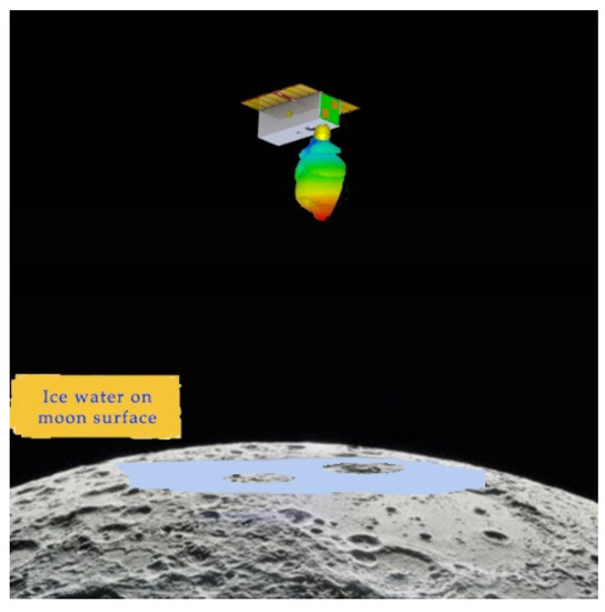
Figure 13.
Smooth-walled horn antenna in remote sensing of moon’s water detection.
This figure illustrates the smooth-walled horn antenna integrated into a CubeSat platform, serving as a crucial component in the remote sensing of water on the moon’s surface. The smooth-walled antenna, optimized through our proposed method, exhibits enhanced performance in transmitting and receiving signals within the frequency range of 160 GHz to 200 GHz. The antenna is utilized in conjunction with a THz subharmonic receiver payload to accurately measure the presence of water on the moon. The CubeSat platform orbits the moon and captures the spectrum of the lunar surface using the smooth-walled horn antenna, allowing us to detect water spectral signatures and identify locations with potential water ice. This innovative approach holds great promise for future space missions, enabling efficient and accurate water detection on extraterrestrial bodies and further advancing our understanding of the cosmos. Figure 13 exemplifies the smooth-walled horn antenna’s critical role in contributing to the success of space exploration and pioneering scientific investigations beyond our planet.
6. Conclusions
The development of compact and high-performance antennas is vital for space exploration, especially when scouting for potential secondary habitats for humans on extraterrestrial planets by usage of small satellites. Our research centers on the optimization of a corrugated horn antenna, using advanced spline curve fitting algorithms to morph it into a smooth-walled design. The simulated smooth-walled antenna showcases improvements, including an 18 dB gain, parameters ranging from −27 dB to −36 dB, and a VSWR range of 1.01 to 1.02, with narrow directivity in the frequency band of 160 GHz to 200 GHz. On the other hand, the corrugated horn antenna demonstrates limited performance, with a mere 1.4 dB gain, parameters between −5 dB to −35 dB, and a VSWR range of 2.23 to 0.35, along with a wider directivity within the same frequency range. Our enhanced smooth-walled horn antenna offers a broader bandwidth, high directivity, and fewer side lobes, enabling efficient and precise detection of materials on extraterrestrial planets. Furthermore, we successfully manufactured and evaluated the functionality of the smooth-walled horn antenna. Utilizing appropriate facilities, we measured critical antenna parameters, including and VSWR, and observed values ranging between −26 dB to −30 dB and VSWR close to 1:1. These results validate the performance enhancements achieved through our proposed smooth-walled algorithm. Our research demonstrates the feasibility of cost-effective and efficient antenna designs for space laboratory applications. The smooth-walled horn antenna’s excellent performance in transmitting and receiving signals within the desired frequency range of 160 GHz to 200 GHz reaffirms its potential for use in CubeSat missions and other space-based applications. The capability to transform corrugated horn antennas into smooth-walled designs, as showcased in this work, offers an accessible and economical approach to fabricate high-frequency antennas. This method holds tremendous value for university student projects and rapid prototyping, enabling researchers to test and iterate antenna designs without incurring substantial costs. Moreover, the smooth-walled horn antenna’s ability to maintain impressive performance parameters, even after fabrication, highlights its potential for integration into space laboratory setups. As a result, our study lays a strong foundation for future advancements in antenna technology, enhancing space exploration endeavors and paving the way for innovative applications in extraterrestrial research.
Author Contributions
Conceptualization, V.R.; methodology, V.R. and W.H.; software, V.R. and W.H.; validation, W.H., W.S. and S.M.A.; formal analysis, V.R. and W.S.; investigation, V.R. and W.S.; resources, W.H.; data curation, V.R. and W.S.; writing—original draft preparation, V.R.; writing—review and editing, W.H., W.S. and S.M.A.; visualization, V.R.; supervision, W.H. and S.M.A.; project administration, W.H. and S.M.A.; funding acquisition, W.H. All authors have read and agreed to the published version of the manuscript.
Funding
This research received no external funding.
Conflicts of Interest
The authors declare no conflict of interest.
References
- Chahat, N.; Jung-Kubiak, C.; Nguyen, T. 1.9-THz Multiflare Angle Horn Optimization for Space Instruments. IEEE Trans. Terahertz Sci. Technol. 2015, 5, 914–921. [Google Scholar] [CrossRef]
- Federici, J.F.; Schulkin, B.; Huang, F.; Gary, D.; Barat, R.; Oliveira, F.; Zimdars, D. Hz imaging and sensing for security applications—Explosives, weapons and drugs. Semicond. Sci. Technol. 2005, 20, S266–S280. [Google Scholar] [CrossRef]
- Hester, J.G.; Chamberlain, J.M. The use of submillimeter and THz imaging for security applications. In Proceedings of the 2012 IEEE International Conference on Wireless Information Technology and Systems (ICWITS) and Applied Computational Electromagnetics (ACES), Maui, HI, USA, 11–16 November 2012. [Google Scholar]
- Aqlan, B.; Himdi, M.; Le-Coq, L.; Vettikalladi, H. Sub-THz Circularly Polarized Horn antenna using Wire Electrical Discharge Machining for 6G Wireless Communications. IEEE Access 2020, 8, 117245–117252. [Google Scholar] [CrossRef]
- Dhillon, S.S. The 2017 Terahertz Science and Technology Roadmap. J. Phys. D Appl. Phys. 2017, 50, 043001. [Google Scholar] [CrossRef]
- Abbosh, A.M. Horn Antenna Advantages for Ultra-Wideband Applications. IEEE Antennas Propag. Mag. 2008, 50, 113–118. [Google Scholar]
- Chen, Y.; Shen, Z.; Zhang, X. Gain Enhancement of Horn Antenna with Metasurface Lens. IEEE Trans. Antennas Propag. 2018, 66, 4160–4164. [Google Scholar]
- Al-Zayed, A.S.; Sheta, A.F. Design of Horn Antenna for Reducing VSWR and Improving Directivity. In Proceedings of the 2018 International Conference on Computer and Applications (ICCA), Doha, Qatar, 25–26 September 2018; pp. 295–299. [Google Scholar]
- James, G.L.; Henderson, A. Antenna Handbook: Volume III Applications; Van Nostrand Reinhold: New York, NY, USA, 2002. [Google Scholar]
- Pal, S.K.; Chakraborty, U.; Chattopadhyay, S. Corrugated Conical Horn Antenna with Improved Radiation Characteristics. IEEE Antennas Wirel. Propag. Lett. 2016, 15, 1492–1495. [Google Scholar]
- Mailloux, R.J. Phased Array Antenna Handbook; Artech House: Boston, MA, USA, 2005. [Google Scholar]
- Sisodia, M.L.; Sharma, G.S. Microwave Devices and Circuit Design; PHI Learning: Delhi, India, 2014. [Google Scholar]
- Alvaro, G.; Keiko, K.; Takafumi, K.; Shini’chiro, A.; Yoshinori, U. Terahertz Corrugated Horns (1.25–1.57 THz): Design, Gaussian Modeling, and Measurements. IEEE Trans. Terahertz Sci. Technol. 2017, 7, 1. [Google Scholar] [CrossRef]
- Mahdi, O.; Mohammad, S.A. Corrugated SIW K band horn antenna. AEU–Int. J. Electron. Commun. 2014, 68, 12. [Google Scholar] [CrossRef]
- Kovitz, J.M.; Manohar, V.; Rahmat-Samii, Y. A Spline-Profiled Conical Horn Antenna Assembly Optimized for Deployable Ka-Band Offset Reflector Antennas in CubeSats. In Proceedings of the 2016 IEEE International Symposium on Antennas and Propagation (APSURSI), Fajardo, PR, USA, 26 June–1 July 2016. [Google Scholar] [CrossRef]
- Hammar, A.; Karandikar, Y.; Forsberg, P.; Emrich, A.; Stake, J. A 340 GHz High Gaussicity Smooth Spline Horn Antenna for the STEAMR Instrument. In Proceedings of the 2014 IEEE Antennas and Propagation Society International Symposium (APSURSI), Memphis, TN, USA, 6–11 July 2014. [Google Scholar] [CrossRef]
- Shi, W.; Hu, C.; Wang, L.-Z. Design and Performance Analysis of a Conical Corrugated Horn Antenna for CubeSat Millimeter-Wave Radiometer. Sensors 2019, 19, 2620. [Google Scholar] [CrossRef]
- Granet, C.; James, G.L. Design of Corrugated horns: A primer. IEEE Antennas Propag. Mag. 2009, 47, 76–84. [Google Scholar] [CrossRef]
- Albani, M.; Sabbadini, M. Design and Testing of Corrugated Horn Antennas for Space Applications. IEEE Trans. Antennas Propag. 2019, 67, 2659–2669. [Google Scholar]
- Salim, M.M.; Azim, R.T.; Islam, M.S.; Islam, M.T.; Misran, N. Design of a Wideband Corrugated Horn Antenna with Improved Radiation Characteristics for Remote Sensing Applications. Electronics 2020, 9, 2007. [Google Scholar] [CrossRef]
- Ghasemi, M.; Oraizi, H. A new design for wideband corrugated horn antenna using hybrid optimization algorithm. Int. J. RF Microw. Comput.-Aided Eng. 2021, 31, e22719. [Google Scholar] [CrossRef]
- MacPhie, R.H. Horn antennas for space applications. In Antenna Engineering Handbook; Volakis, J.L., Ed.; McGraw-Hill: New York, NY, USA, 2007. [Google Scholar]
- Jensen, M.A.; Johnson, J.W.; Rahmat-Samii, Y. Electromagnetic scattering by objects above or below a plane surface. IEEE Trans. Antennas Propag. 2000, 26. [Google Scholar]
- Batchelor, J.C.; Brown, A.; Clarke, A.; Griffiths, D. A broadband dual-polarized corrugated horn for the 15–37 GHz band. IEEE Trans. Antennas Propag. 2001, 49, 20–26. [Google Scholar]
- Wu, K. Antenna Design and Fabrication for 5G Communication Systems. Electronics 2020, 9, 992. [Google Scholar] [CrossRef]
- Shi, W.; Hu, C.; Wang, L.-Z. Smooth-walled corrugated horn antenna for CubeSat THz spectrometer payload in planetary water detection missions. Prog. Electromagn. Res. Lett. 2020, 85, 101–108. [Google Scholar] [CrossRef]
- Granet, C.; James, G.L.; Bolton, R.; Moorey, G. A Smooth-Walled Spline-Profile Horn as an Alternative to the Corrugated Horn for Wide Band Millimeter-Wave Applications. IEEE Trans. Antennas Propag. 2004, 52, 848–854. [Google Scholar] [CrossRef]
- Campa, R.; Szocik, K.; Brddock, M. Why space colonization will be fully automated. Acta Astronaut. 2019, 143, 162–171. [Google Scholar] [CrossRef]
- Khan, N.S.; Hu, W.; Xie, Z.; Wu, J. Design of a dual-band circularly polarized corrugated horn antenna for 5G and millimeter wave applications. IEEE Trans. Antennas Propag. 2020, 68, 2005–2010. [Google Scholar]
- Robinson, J.; Sinton, S.; Rahmat-Samii, Y. Particle swarm, genetic algorithm, and their hybrids: Optimization of a profiled corrugated horn antenna. In Proceedings of the 2002 IEEE Antennas and Propagation Society International Symposium, San Antonio, TX, USA, 16–21 June 2002. [Google Scholar] [CrossRef]
- Rastinasab, V.; Hu, W.; Tahmasebi, M.K. Water Recognition on the Moon by Using THz Heterodyne-Spectrometer for Identifying the Appropriate Locations to Extract Water for Providing Oxygen for Breathing and Fuel for Spaceships’ Propulsion on the Moon with CubeSat. Aerospace 2021, 8, 186. [Google Scholar] [CrossRef]
- Bruno, R.; Christophe, S. Carbon-rich icy moons and dwarf planets. Earth Planet. Sci. Lett. 2023, 612, 15. [Google Scholar] [CrossRef]
Disclaimer/Publisher’s Note: The statements, opinions and data contained in all publications are solely those of the individual author(s) and contributor(s) and not of MDPI and/or the editor(s). MDPI and/or the editor(s) disclaim responsibility for any injury to people or property resulting from any ideas, methods, instructions or products referred to in the content. |
© 2023 by the authors. Licensee MDPI, Basel, Switzerland. This article is an open access article distributed under the terms and conditions of the Creative Commons Attribution (CC BY) license (https://creativecommons.org/licenses/by/4.0/).