Article

Problem-Solving in Product Innovation Based on the Cynefin Framework-Aided TRIZ

1
School of Mechanical Engineering, Hebei University of Technology, Tianjin 300401, China
2
National Engineering Research Center for Technological Innovation Method and Tool, Hebei University of Technology, Tianjin 300401, China
3
Department of Mechanical Engineering, University of Manitoba, Winnipeg, MB R3T 5V6, Canada
*
Author to whom correspondence should be addressed.
Appl. Sci. 2022, 12(9), 4157; https://doi.org/10.3390/app12094157
Submission received: 28 March 2022 / Revised: 14 April 2022 / Accepted: 18 April 2022 / Published: 20 April 2022
(This article belongs to the Section Mechanical Engineering)

Abstract

:
Different problems in the process of product innovation are often caused by external environmental changes of the product. There is a lack of research on classifying the problems associated with product environment changes to aid in applying tools of the Theory of the Solution of Inventive Problems (TRIZ) for problem-solving. This paper proposes a Cynefin framework to classify the problems into disorder, chaotic, complexity, complicated and simple areas according to the external environment changes. Each area of problems is then solved by corresponding design tools in TRIZ. Chaotic and complex problems are converted into complicated or simple areas by the technology evolution and effect search. Complicated or simple areas are combined considering conflicts expressed by an Element-Name-Value (ENV) model. Key conflicts are determined by simplified rules of a node conflict network. A problem-solving methodology in product innovation is proposed based on Cynefin framework-aided TRIZ. The proposed method is applied in the design of an enterprise SJL900/32 mobile bridge erecting machine.

1. Introduction

A process of product innovation faces different problems to meet the final design requirement [1,2]. Choosing appropriate tools for problem-solving is a challenge in the product innovation process [3,4]. As the concept design decides more than 70% of the total cost of the final product development [5], it is important to study different types of problems and corresponding measures in the conceptual design stage.
Design problems in the process of product innovation are often caused by external environment changes such as market pulling and technology driving. Market pulling stems from needs for customer satisfaction, customer experience, and behavior [6]. Technology driving is the initiative in product innovation based on new technologies [7]. When the external environment changes, a product needs to respond to the change [8]. In the conceptual design process, the traditional design process focuses on finding solutions, which ignores the efficiency of finding solutions and new problems caused by conflicts between solutions and existing systems [9,10,11,12]. The Theory of the Solution of Inventive Problems (TRIZ) is an effective method for product innovation and is widely used in various fields [13,14]. However, because of a large number of problem-solving tools and many possible ways of solving problems in TRIZ [15,16,17], when these tools are used to solve problems, it is difficult to choose the right tool to solve different problems. There is no easy way to approach a logical and clear structured process of problem-solving.
The Cynefin framework, which originated in the field of knowledge management, provides a solution model for different problems [18,19,20]. Under the Cynefin framework, problems are divided into five areas: simple, complicated, complex, chaotic, and disorder according to the causality of the problems [21,22,23]. Assigning solutions according to the problem area helps to make the right decision. A problem can be transformed into several areas under different constraints to reduce its complexity dimension, which provides a standard process for problem-solving. This is the same idea as the TRIZ problem-solving process. However, according to the existing literature studies, the Cynefin framework has not been used in product innovation adequately. It is necessary to reconstruct the problem area according to the characteristics of the product innovation process to facilitate the classification of the problem and to integrate it with TRIZ for the solution of the area problem.
In summary, this paper integrates the Cynefin framework and TRIZ to guide users using design tools in the product design process. The Cynefin framework is used to analyze the problem type and determine the problem area based on the external environment changes of the product, which aids in the application of a tool for problem-solving. Problems in complicated and simple areas are combined by considering conflicts expressed by an Element-Name-Value (ENV) model [24]. A multi-conflicts parameter network is established according to the EVN model. Node conflict network simplified rules are constructed to identify key conflicts. The disorder problem is split based on problem characteristics. Chaotic and complex problems that cannot be solved directly by the extraction of conflicts are transformed into complicated or simple problem areas through technological evolution [25]. Effect searching [26] is introduced to reduce the problem complexity dimension for a standard structured model of product innovation. Contributions to this research are as follows:
  • The Cynefin framework is reconstructed by the conflict, making it compatible with the product innovation process characteristics.
  • A reconstructed Cynefin framework is applied to aid TRIZ in the problem-solving process. It provides a new method for the application of design tools in TRIZ from the perspective of problem classification to solve difficulties in applying TIRZ.
  • The creation of simplified rules for the node conflict network improves the method of identifying key conflicts in the multi-conflict solution process, largely reducing the workload of designers in solving multi-conflict problems, which in turn improves the product innovation process under the Cynefin framework.
The remainder of this paper is organized as follows. Section 2 presents the development status and problems of TRIZ, Cynefin framework, and conflict. Section 3 introduces the problem-solving process of the Cynefin framework to assist TRIZ, including reconstruction of the Cyneifn framework, the transformation of problem areas, and solution methods within each area. Section 4 describes the design process of a mobile bridge erecting machine to prove the proposed method. Section 5 discusses the proposed method and summarizes the paper.

2. Related Research

There are different methods for product innovation design as the design process is diverse itself. The classic Pahl and Beitz theory divides the design process into four stages: design task confirmation, conceptual design, technical design, and detailed design [27]. The design of a particular product can follow this process exactly, or select parts of it. The Ulrich and Eppinger theory provides methods for the product design process and subsequent design of services, product development economics, etc. [11]. Analogous design expands the set of generated ideas using similar relationships from solutions to analogous problems to augment and extend concept generation methods [28]. The Ullman method considers the product design for the final product development. In the conceptual design phase, analogous, patent searches and conflicts in TRIZ are used to search for conceptual ideas [29]. TRIZ is mainly used in the conceptual design phase to solve various conflict-focused invention problems. Although TRIZ has been widely used, and some traditional design processes have incorporated TRIZ for problem-solving [10,29], there are still some shortcomings in using design tools in TRIZ effectively in engineering practice. The details are as follows.

2.1. Design Tools in TRIZ

Design is a complex activity in product development. TRIZ was proposed by Altshuller based on research on over 400,000 patents as a theory of innovation for product design, which is rated among the most articulated and effective sets of techniques for supporting the initial stages of engineering design. It reveals the inner laws and principles of creation and invention by clarifying and highlighting conflicts in a system [30,31]. As opposed to other tools of analyzing problems, such as brainstorming, mind mapping, and lateral thinking [32], it has a large number of analytical and problem-solving tools, such as function analysis, trimming, technical evolution, effects, and conflicts, which helps to analyses problems and offers direct solutions [33,34,35]. TRIZ has been widely applied in the product innovation process, but due to its large number of tools, it is difficult to choose the right tool in the application process. The wrong use of tools usually leads to a waste of effort [36,37]. Some processes of using design tools in TRIZ and classifications of tools have been established. For example, Algorithm for inventive problem solving (ARIZ) is a classic tool for complex problem-solving in TRIZ to overcome the inertia of thinking and generate innovative solutions. But many of the tools included in this process are still in a confusing state and the application process is too complicated [32]. Zlotin [38] divided design tools in TRIZ into three groups for analytical, knowledge-based, and psychological processes, each group contains several design tools in TRIZ. Moehrle [39] provided a framework to structure tools according to the field and the importance of applications for problem analyzing and solving. Although there are some methods in classifications of design tools in TRIZ and problem-solving processes, they do not consider the accurate matching process between the problem and tool. This results in a problem for users to choose an appropriate tool for different problems in the application process. Therefore, a well-structured process is needed to identify tools effectively for problem-solving in product innovation.
The Cynefin framework is an approach to problem classification for aiding users in the decision-making process. It helps to recognize the existing and new problems to make the best decision by solving new problems in the same way [18,21]. This is consistent with the choice of the best design tool in TRIZ for different types of new problems. In order to improve problems in the TRIZ application, this paper adopts the Cynefin framework from the point of view of problem classification and gives the corresponding solution tools for each type of problem to assist the application of TRIZ in the problem-solving process. The user only needs to identify the area of the problem within the Cynefin framework according to the characteristics of the problem. The solutions for different areas are then applied. It reduces the difficulty in the selection of design tools in TRIZ.

2.2. Cynefin Framework

Cynefin is a Welsh word meaning habitat or place, which can be understood as the location of affiliation [40]. The Cynefin framework is used to analyze external environment changes in systems. For different environmental changes, different measures for solving similar problems in the past are used. The Cynefin framework considers five areas of causality of the problem, including simple, complicated, complex, chaotic, and disorder areas [21,41,42], as shown in Figure 1. The characteristics of each problem area are as follows. (1) The causality of simple problems is stable and clear, and the causes of the problems are clearly visible and understood in a uniform way. The simple problem is dealt with by the sense-categorize-respond model. Specifically, the problem is classified to match past experience, and the solution is found based on the existing experience. (2) The causality of complicated problems is not obvious, and the network is intertwined. A problem may be caused by multiple reasons, or one cause leads to multiple results, and these relationships are not intuitive. The problems are dealt with by the sense-analyze-respond model. Experts in related fields analyze the problems to form the solution. (3) The causality of complex problems exists, but the causality cannot be determined before the problem is solved. The problem needs to be deduced through review, which is dealt with by the probe-sense-respond model. Specifically, the problems are solved exploratory. The causality of the problem is dynamic and uncertain to require the tentative emergence of solutions. A preliminary plan is formed after problem screening, and the plan is then revised based on the feedback. (4) The causality of the chaotic problem is unknown. The cause of the problem cannot be understood as uncertain changes. It is meaningless to find the problem reason. Decisive measures are required to stop the problem from continuing. The chaotic problem is dealt with by the act-sense-respond model. Specifically, an action has to be taken quickly for its interventions and transition to the complex problem. The problem solution can then the sought further. (5) The disorder problem is the starting point for the analysis of the problem and consists of one or more of the above-mentioned areas. The problem in this area is divided into one or more of the above-mentioned areas based on the analysis of the external environment. The problem can then be handled with the problem-solving method of the corresponding area.
The Cynefin framework has been used in a variety of fields for different applications. It has served as a starting point for the problem analysis in decision-making [43]. Based on the results of studies [21,44], Mann [45] discussed the system area of the Cynefin framework in response to the external environment changes for problem-solving. The Cynefin framework was applied in the complexity analysis of the product innovation process to analyze both the type of external environmental changes and the improvement process of the technological system. The Cynefin framework is also used in fields of knowledge management [46,47] and healthcare [48,49,50]. The problem analysis using the Cynefin framework provides decision-makers an appropriate tool to consider uncertain and environmental changes for the best solution to the problem.
The analysis of problems under external environment changes is a dynamic and uncertain decision-making process. Existing applications of the Cynefin framework are only for identifying problems. That is insufficient to classify problems encountered in the process of product innovation and transform the problem into the solution area. It is noted that the framework can be redefined by users to support decision-making based on specific scenarios [18,21]. Therefore, this paper combines the Cynefin framework with conflict-solving tools of TRIZ and Ashby’s law [51] to reconfigure the existing Cynefin framework as an effective tool for problem-solving of product innovation.

2.3. Conflict

In the process of product innovation, the core of applying TRIZ is to solve problems caused by conflicts in standardized forms [52]. There are three types of conflicts including management conflict, physical conflict, and technical conflict [53]. When solving engineering problems with TRIZ, only physical and technical conflicts are usually considered. These two conflicts can be transformed by the change in their parameters [54]. A physical conflict appears when a subsystem or component is supposed to have one characteristic in order to achieve a certain function, but at the same time, another characteristic is opposite to this characteristic [55]. For example, in order to increase the capacity of a cup, its volume needs to be increased. In order to carry the cup easily, its volume should be reduced. The volume of the cup is to be both larger and smaller, which is a physical conflict. Principles of spatial separation, temporal separation, condition-based separation, and whole-part separation can be applied to resolve conflicts. Mann [56] found a relationship between these principles of separations and 40 principles of the invention for resolving technical conflicts. For each separation principle, there can be multiple invention principles corresponding to it. When a solution cannot be formed by using the separation principle, the solution can be found by using the invention principle corresponding to each separation principle. A technical conflict is an action that leads to both useful and harmful results [57]. For example, in order to increase the capacity of a cup, it is necessary to increase its volume, but this results in a less portable cup. This is a technical conflict. Useful and harmful results are first expressed by 39 standard engineering parameters. Then, conflict can be solved using the innovation principle, which is looked up by the conflict matrix [58].
As the number of components increases, the product complexity also increases. The number of conflicts in the design process can evolve from a single conflict to multi-conflicts [59]. Conflict tools of the classical TRIZ may be no longer applicable. The general theory of powerful thinking (OTSM) applies the classical TRIZ model [60,61] for new tools to analyze complexity problems according to a hierarchical structure in identifying key issues and building a multi-conflicts model [62,63]. Khomenko [64,65] proposed OTSM with four conflict resolution tools. Cavallucci [66,67] refined OTSM for problem flow network techniques to solve multi-conflict problems. It applied the ENV model and graph theory [68,69] for multi-conflicts to construct a parameter network according to the relationship of parameters in the ENV model, but the parameter network is not appropriate to decide the interrelationship among conflicts. Zhang [70] determined the key conflicts and constructed a conflict network by assigning weights to control and evaluation parameters. Wang [71] and Sun [72] used a hierarchical analysis method to calculate the weights of each conflict in the conflict network and determine the order of conflict solutions. However, the assignment process is subjective and the calculation process is tedious. Therefore, a multi-conflicts parameter network was built first based on the relationship between control and evaluation parameters of the multi-conflicts model expressed by ENV, and the parameter network was then transformed into a node conflict network. Node conflict network simplified rules were constructed from the multi-conflicts solving process in the existing studies.
In summary, it is found that there is a close dependency relationship between the Cynefin framework, design tools in TRIZ, and conflict. Firstly, a key to the product innovation process is the resolution of problems caused by conflicts. The Cynefin framework that has been restructured from a conflict perspective can effectively identify an area for problems encountered in the product innovation process. Secondly, the reconfigured Cynefin framework is based on a problem classification perspective. Different areas of problems are assigned appropriate tools in TRIZ to assist in the application of TRIZ in the problem-solving process. Finally, simplified rules are proposed for the node conflict network with multiple conflicts in the application of TRIZ to solve problems under the Cynefin framework.

3. Proposed Method

In order to effectively apply the Cynefin framework to aid TRIZ applications, the problem characteristics of each area are restructured from a conflict perspective. According to the reconstructed Cynefin framework, design tools in TRIZ are assigned in each area for problem-solving. The disorder area is the stage to analyze the problem area. The problem-solving area contains chaotic, complex, complicated, and simple areas. The chaotic, complex, and simple areas are directly assigned to existing TRIZ tools. The methods of identifying key conflicts are improved for the multi-conflict problem in the complicated area. The problem to be solved is matched to the problem characteristics of each area within the Cynefin framework. The problem is then solved directly using the tool pre-assigned to that area. When an existing problem is solved, new problems may come with new characteristics. Based on the characteristics of the new problem, the problem can be determined for the related area to apply tools in the area until the problem is completely solved.

3.1. Cynefin Framework Reconstructing

A product consists of multiple components with interrelationships to achieve its functions. It is necessary to continuously improve the product to increase the product competitiveness in the market. When a component is upgraded to improve the performance of some aspects of the product, it may affect other components associated and the product performance. If these effects are negative, there is a design conflict [52].
One of the keys to problem-solving is to overcome conflicts of problems. Conflicts can be expressed in standardized forms [15,52]. Therefore, the Cynefin framework is reconstructed from a conflict perspective for the mechanical product innovation process.
Conflicts exist in the definite technology and uncertain technology system. In a definite technology system, as the system principle and working components are known, which already exist but do not meet the needs of users, conflicts can be extracted directly by the analysis of relevant components. The uncertain technology system is changeable because of technology evolution, new functions added or trimming, the executed components are unknown, and the conflict cannot be extracted directly by the analysis of components with problems. In a Cynefin framework, a definite technology system contains simple and complicated problem areas. The uncertain technology system has complex, chaotic, and disorder areas problems.

3.1.1. Areas in the Cynefin Framework Based on Conflicts

Characteristics of problem areas under the Cynefin framework based on conflicts are redefined as follows.
1.
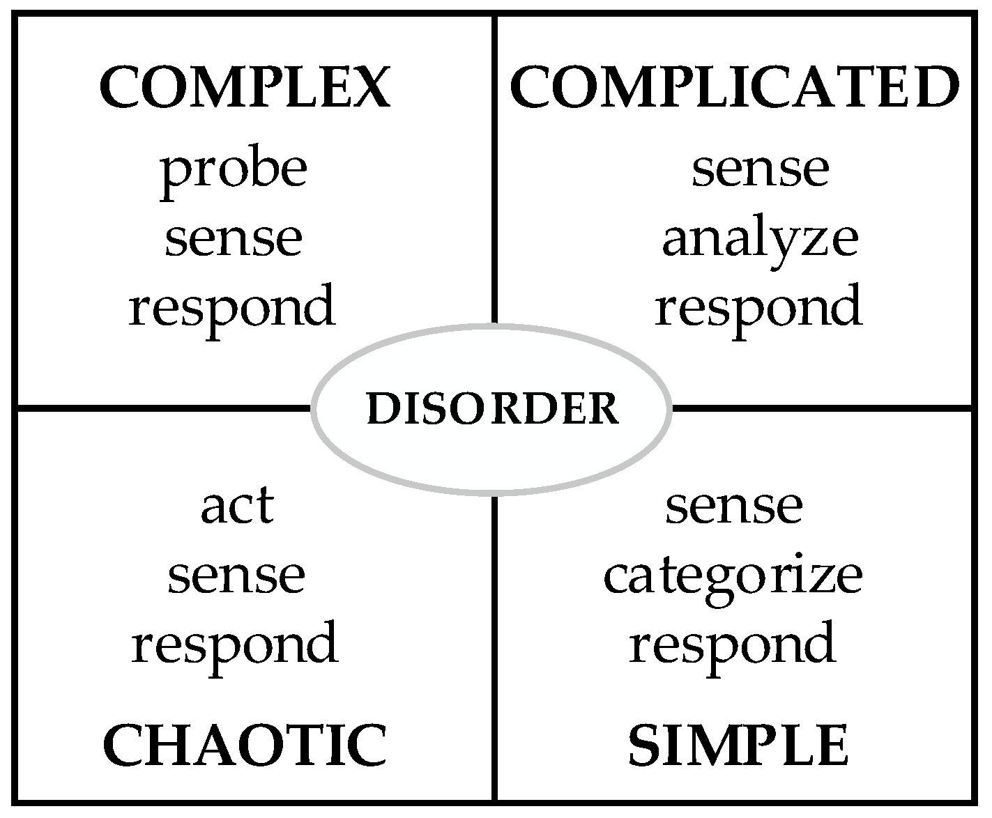
Simple problem area: The cause-effect relationship in this area is a one-to-one correspondence, as shown in Figure 2a. The relation from analogy to conflict is shown in the improvement of each component with problems of other components, but there is no mutual influence between improved and affected components. Extracted conflicts are independent, as shown in Figure 2b, where C1 and C2 represent conflicts.
2.
Complicated problem area: The cause-effect relationship is in a mesh structure, as shown in Figure 3a. The analogy of the relationship between conflicts shows that improvement of each component will affect other components, and there is an interconnection between improved and affected components. Extracted conflicts are multi-conflicts, as shown in Figure 3b, where arrows represent the influence relationship between conflicts.
3.
Complex problem area: A cause-effect relationship exists, but it can only be established after the initial exploration of the incomplete solution is formed, as shown in Figure 4a. The analogy to conflict manifests itself as the addition of a known new function to the current system or the adoption of other resources within or outside the system to implement the current system function by trimming components of the system. Since the working principle of the newly added function or the function where the trimming component is located has not been determined, the component that implements the principle cannot be identified and the conflict cannot be extracted. The conflict can be extracted after a tentative solution is found for a preliminary solution. The problem in this area is to attach new known functions or trimming, as shown in Figure 4b.
4.
Chaotic problem area: The cause-effect relationship is not considered in this area. Measures are required to convert it to the complex area. Analogy to conflict requires not considering the extraction of conflict, but determining the new function or function improvement of the next generation of products through the law of technological evolution. The chaotic problem area is then transformed into a complex problem area. (The new functions added to this area or the direction of function improved are not known at the beginning).
5.
Disorder problem area: The technology system contains multiple area types of the above-mentioned problems, which need to be split into several problems. Each problem is then considered in one of the corresponding areas.

3.1.2. Reconstructed Cynefin Framework

Ashby’s law states that there are three change stages in a system: changes in inputs from environments, in responding to the environment changes with appropriate measures, and in measured results [44]. As a system continues to evolve, its system internally changes with the external environment changes, i.e., the internal system response matches its external environmental change [73].
In conjunction with Ashby’s law and the definition of problem areas in the product innovation process, the Cynefin framework is reconstructed, as shown in Figure 5. Above the ashby line is the resilience area, where measures of the product technology system with external environment changes are in a redundant state. It indicates that the ability of the system to deal with complexity problems internally is greater than the complexity of the environment. At the Ashby line, the ability of the system to handle complexity problems internally is equal to the complexity of the external environment. At the bottom of the line, the system’s response is insufficient to counteract changes brought by the external environment, and the system deteriorates. Therefore, the condition for maintaining the system stability is to locate on or above the line. When the external environment is transformed, the system adopts the problem-solving tool based on the problem type.
The problem is analyzed in the disorder area and then divided into other corresponding areas. The chaotic and complex problem area is an uncertain technical system. Problems in these areas need to be converted into a complicated or simple problem areas for solving by conflict tools. Problems in the disorder area are directly split and divided into other corresponding problem areas. Chaotic problem area requires rapid actions to stop the problem development. Therefore, the problem in the area can only determine the direction of improvement, and it can only be converted into a complex area. Problems in the complex area have reached the function level, and once principles and components of the function are determined, conflicts can be extracted and converted from the uncertain technical system to the definite technical system. Depending on whether conflicts are independent or not, the conversion to the complicated or simple areas can be made.

3.2. Problem-Solving and Area Conversion

3.2.1. Disorder Problem Area

This problem area is the starting point of the problem analysis. If the problem to be solved matches the characteristics of a problem area within the Cynefin framework, it can be directly divided into the corresponding problem area. If the problem exhibits the characteristics of multiple problem areas within the Cynefin framework, the problem is divided into sub-problems based on the problem area characteristics of each area within the Cynefin framework. It is then divided into the corresponding problem area to be solved, as shown in Figure 6.

3.2.2. Chaotic Problem Area

A product technology life cycle curve is shown in Figure 7. The existing technology life cycle curve A of the product will rise with the technology’s performance until it reaches the technology performance limit, point d. After that, it will enter the performance decline period, new alternative technologies will appear (e.g., B), and existing technologies will be withdrawn from the market. The evolutionary process of the technology possessed by the current product from point a to point d and the jump from point d to point e is uncertain. There is no way to determine how far the product will evolve next or which evolutionary curve it will jump to. However, for sustainable development, the product must take timely measures to prevent being eliminated from the market. The chaotic problem area coincides with this feature, problems in this area are solved by combining the technological evolution as follows.
By analyzing the position of the current product’s technical performance in the technical life cycle curve through patents analysis, the technical evolution can be adopted for the product technical evolution. If the performance limit has not been reached, the product can be improved based on the current technology. When the performance limit is reached, it is necessary to find other alternative technologies to achieve breakthrough innovation.
This problem area uses technological evolution to determine product functions in the next technological stage. The system is then transformed from the current chaotic area to a complex problem area.

3.2.3. Complex Problem Area

The technology system is either to add new functions from the technology evolution of the chaotic area or from customer requirements, or to replace working principle of original functions by trimming. Since the working principle of the function, implementation has not been determined and corresponding components have not been identified, it is an uncertain technology system where conflicts cannot be extracted directly. Therefore, a conversion of the uncertain technology system to a definite technology system is required. To increase the diversity and innovativeness of the solutions, an online effect database created by Oxford [74] is used to search emerge several solutions in this field and across fields. The optimal solution can then be selected as the initial original understanding through solution screening. An uncertain technical system is then converted to a definite technical system and the problem is converted from a complex problem area to a complicated or simple problem area.
Adding function or replacing working principle of the original function by trimming is represented by F, which is a combination of several sub-functions Fi. Fi can be further divided into several Fij (i = 1, 2, 3…, j = 1, 2, 3…), as shown in Figure 8.
When a function is broken down into sub-functions, some sub-functions (e.g., F11, F12) can be performed by components already in the system, so there is no need to find the working principle to implement the sub-function. Some sub-functions (e.g., F31) have no available components in the system to perform them, called unimplemented sub-functions, and are described by parameters in the effect database. Parameters of the effect database consist of two parts, Action and Object, as shown in Figure 9.
Based on parameters corresponding to sub-functions, the original solution is searched. The technical feature that best matches the sub-function is selected as the preliminary solution. For example, if a solid object is to be broken down in water, the solution needs to have technical features that allow the operation in water. The individual sub-function in the preliminary solution is implemented by components that already exist in the system or by newly added components. However, the exclusivity of the system can lead to conflicts between the newly added components and existing components of the system. According to problem area characteristics in the reconstructed Cynefin framework, conflicts cannot be extracted directly in a complex area of the uncertain technical system, the definite technical system contains both complicated and simple problem areas where conflicts can be extracted. The complex problem area is then converted to a complicated or simple problem area.

3.2.4. Complicated and Simple Problem Area

A complicated or simple problem area is a definite technical system where conflicts can be extracted directly. First, interactions between system components, products, and super-system components are identified to construct an interaction matrix as shown in Figure 10a, where + indicates that the element acts on other elements, − shows that the element is acted by other elements. Then, a function model [75] of the technical system is created based on the interaction matrix as shown in Figure 10b. Insufficient, redundant, and harmful functions. Deficient functions in the function model are then analyzed to identify associated components for the conflict extraction.
The conflict model corresponding to a complicated problem area is multi-conflicts, and the conflicts interact with each other. In order to simplify the problem-solving process, key conflicts are identified and solved first, and other related conflicts can be eliminated or simplified by solutions to the key conflicts. Therefore, conflicts expressed by the ENV model are used to assist in the creation of conflict networks, as shown in Figure 11. As physical conflicts and technical conflicts are interchangeable, the physical conflict and control parameter is in one-to-one correspondence. In order to facilitate the construction of a node conflict network, physical conflicts are expressed in terms of control parameters in the EVN model.
Where, E1, E2, E3 are system elements; CP1 is the control parameter, a yellow area in the figure; EPi is the evaluation parameter, blue area in the figure; Va+ and Va− denote positive and negative values of control parameters, green area in the figure; V+ and V are positive and negative values of evaluation parameters, grey area in the figure.
If the evaluation and control parameters of each conflict are different and do not affect each other, it is an independent conflict and a simple problem area that can be solved one by one by using the conflict-solving tool in TRIZ. If the evaluation parameters and control parameters are partly the same or affect each other, it is a multi-conflicts problem and a complicated problem area. Solution steps are as follows.
1.
The parameter network of multi-conflicts is established according to the parameter relationship between each conflict expressed by the ENV model, as shown in Figure 12. The dashed box shows the control parameters and the right side shows the evaluation parameters. To simplify the connection of the parameter network, the change of the control parameter to a certain direction is connected only to evaluation parameters with the negative impact. For multiple control parameters, the same evaluation parameters are merged. The parameter pointed by the arrow of the connecting line indicates that the parameter is affected by the parameter.
2.
The node conflict network is established according to the connection relationship between conflicting parameters in the parameter network, as shown in Figure 13, where, Ci represents the conflict node, and the arrow represents the influence relationship between conflicts. For example, the control parameter CP1 of conflict one affects the control parameter CP4 of conflict four in the multi-conflicts parameter network, this is expressed in the node conflict network as node conflict C1 affecting node conflict C4.
3.
Building simplified rules for node conflict networks. Some constructed node conflict networks are shown in Figure 14.
Node conflict connection types [70,71,72] are summarized according to the relationship of each node between node conflict networks in Figure 14. The key conflict of the node conflict network in the existing research is summarized to construct simplified rules of the network, as shown in Table 1.
According to simplified rules one to five, the node conflict network is updated after key conflicts are resolved. For the updated node conflict network, rules one to five are reapplied to determine key conflicts.
Taking the multi-conflicts network in literature [76] as an example, the node conflict network is established according to the above steps, as shown in Figure 15.
According to combined node conflict partial network five (here rules one, two, and three are combined), it is concluded that C1 is the key conflict, and the solution is preferred, which is consistent with the key conflict in the original literature and verifies the rules.
The above rules for the node conflict network simplification are based on the limited existing studies. The simplified rules need to be improved if there are other types of combinations required.
4.
Conflicts are solved according to the node conflict network simplified rules. Solutions to each conflict are then aggregated to form one or more complete innovative design solutions.
5.
A function may be achieved by multiple technologies. A system may have a negative effect on accomplishing the desired function. In order to evaluate the positive and negative effects to select the best solution, Equation (1) is used [77]. The solution with the high ideality is selected as the final design solution.
I = B i E j + H k
where, I (Ideality) is the idealized level, B i (Benefit) denotes all useful characteristics, E j (Expense) denotes the cost of the product, and H k (Harm) denotes undesirable effects.
The Ideality level is decided by a combination of Benefits, Expenses, and Harms. Benefits are evaluated in terms of function and efficiency. Expenses are evaluated for the cost of the product. The evaluation indicator for Harms is the operating time that completes the function. To avoid different levels of indicators affecting the ideality results, all evaluation indicators are evaluated on a scale of one to five.

3.2.5. Process for Problem-Solving under Cynefin Framework

A process of the problem-solving in product innovation is constructed under the Cynefin framework by integrating the above processes, as shown in Figure 16. The steps are as follows.
  • Identifying product problems. Analyze the problem features in the disorder area, if it contains more than one feature, the problem needs to be decomposed and divided into the corresponding areas, otherwise, it goes directly to the other areas.
  • For problems in chaotic and complex areas, they are converted into the complicated or simple problem areas. Otherwise, this step is skipped.
  • For a definite system including complicated and simple problem areas, problematic functions of the system are analyzed based on the function model. A complicated area or simple problem area is determined based on the relationship between the parameter of conflicts.
  • For the complicated problem area, a node conflict network is established based on conflicts expressed by the ENV model. Using the conflict network simplified rules, design tools in TRIZ are used to solve the conflict. For a simple problem area, it is sufficient to solve the conflicts one by one.
  • Solutions to the above conflicts are summarized as the final innovative solution. If there are multiple aggregated solutions, the solution with a high ideality is selected as the final solution through the solution evaluation.

4. Case Study

The use of prefabricated beams has greatly improved efficiency of the road and bridge construction. In order to adapt to tunnel beam erection, the SJL900/32 mobile bridge erecting machine was developed [78], as shown in Figure 17, drawn by UG software. However, there are some shortcomings in its applications. Due to the complicated topography of the construction site, prefabricated beams cannot be made on-site. A mobile bridge erecting machine is therefore required to transport beams from the location where prefabricated beams are stored as shown in Figure 18. The beams are then transported to the construction site, as shown in Figure 19. When distances are long, resulting in low efficiency. It is proposed to use the existing beam trucks to transport prefabricated beams from the storage site to the construction site, and then load the prefabricated beams onto the mobile bridge erecting machine at the construction site. However, the current mobile bridge erecting machine does not have the capability to load prefabricated beams directly from the beam truck on the construction site.

4.1. Identifying Problem Areas in the Disorder Problem Area

According to the customer requirement, an additional function is required in the existing mobile bridge erecting machine to load beams at the construction site. Based on the classification of problems in the Cynefin framework, the newly added function is known that no longer needs to be analyzed through technical evolution and fits the characteristics of a complex problem area within the Cynefin framework.

4.2. Problem-Solving in the Complex Problem Area

For the complex problem area in the Cynefin framework, according to Ashby’s law, the solution should be compatible with external environment changes to search problem-solving tools as follows.

4.2.1. Identifying Unimplemented Sub-Functions

Based on the problem that the current mobile bridge erecting machine does not have the capability to load prefabricated beams directly from the beam truck, the new function to be added to the mobile bridge erecting machine is the Beam truck lifting beam. The function breakdown of the preliminary solution is shown in Figure 20, contents in the bracket explain functions or similar functions in different parts.
Sub-functions of the newly added function, the transport beam (Beam truck) and move beam (Beam truck), can be performed by the existing beam truck. The fix beam (Crown block of lifting beam) and lift beam (Crown block of lifting beam) is performed by the existing crown block of the lifting beam. The only sub-function that cannot be performed by the existing system is the Pass Beam truck (Rear wheel).

4.2.2. Effect Search to Determine Preliminary Solution

In order to achieve the sub-function of Pass Beam truck (Rear wheel), the span of the wheel span is increased. It is converted to the effect parameter description, as shown in Table 2. An effect database is searched for 188 relevant effects, as shown in Figure 21. Considering the heavy load caused by the prefabricated beam during the beam erection, the Hydraulic ram with a high load-bearing capacity is selected as a preliminary solution.
According to the effect search, the preliminary solution is established, as shown in Figure 22. According to the change of erection demand, the requirement of span distance between rear wheels in different states is satisfied by the expansion and contraction of Hydraulic ram. By selecting the Hydraulic ram to complete the unimplemented sub-function to form the preliminary solution, the system is transformed from a complex area in an uncertain technical system to a definite technology system according to problem area characteristics in the Cynefin framework. The problem is then converted from the current complex problem area into a complicated or simple problem area.

4.3. Decision of Complicated or Simple Problem Area

4.3.1. Building the Function Model

The interaction matrix of system components, products, and super-system components for the preliminary solution is created, as shown in Figure 23a, where a, b, c, d, e, f, g, h, i, j, k are Hydraulic ram, Draw tube, Rear truck, Front outrigger, Main girder, Front truck, Mobile outrigger, Crown block of lifting beam, Beam to be erected, Beam erected, and Load beam truck, respectively. A function model of the preliminary solution is built, based on the interaction matrix, as shown in Figure 23b. From the function model, problematic functions of the preliminary solution are identified as follows.
  • When the beam truck delivers the beam from the rear of the mobile bridge erecting machine, the distance between wheels on both sides of the rear truck cannot be increased indefinitely due to the limited width of the erected road.
  • When the beam truck delivers the beams underneath the mobile bridge erecting machine lifting device, the main girder and rear truck of the mobile bridge erecting machine cannot pass underneath because of the small distance from the ground.
  • When the span of wheel distance on both sides of the rear truck is large, the size of the Draw tube and diameter of the Hydraulic ram is too large to meet manufacturing requirements.
Components involved in these problematic functions are the rear truck, main girder, Hydraulic ram, and Draw tube. Conflict areas are identified from related areas.

4.3.2. Extracting Conflict Based on the ENV Model

The conflict is extracted from components corresponding to the above problematic functions and expressed in the ENV model, as shown in Figure 24. From the conflict in the ENV model, different control and evaluation parameters influence each other, in the complicated problem area.

4.4. Problem-Solving in Complicated Problem Area

4.4.1. Building Conflict Network

Based on conflicts extracted from problems in the preliminary solution, a multi-conflicts parameter network is established, as shown in Figure 25.
Based on the interconnection between parameters in the multi-conflicts parameter network, the node conflict network is established, as shown in Figure 26.

4.4.2. Identifying Key Conflict

Two node conflict networks are formed by the conversion of the multi-conflicts parameter network. Node-conflict network one consists of two chain node conflict partial networks, and rule five is adopted. Node conflict C2 is both the origin conflict of chain node conflict partial network C2-C1-C6-C5 and the origin conflict of chain node conflict partial network C2-C6-C5, so C2 is the key conflict with priority for solving. Node conflict network two is a chain node conflict partial network, rule one is adopted and the priority is to resolve conflict C3.

4.4.3. Conflict Solving

The conflict of rear truck existence C2 is first solved. When the beam truck delivers beams from the rear, the rear truck needs to be absent in order that the beam truck is able to deliver the beam to the bottom of the crown block of the lifting device. When the beam delivery is completed and the mobile bridge erecting machine transports the beam to the erection position, the rear truck needs to be present again to support the transportation. The presence of the rear truck differs in different time conditions, which is a physical conflict based on the time separation principle. According to the correspondence between the separation principle and invention principle, invention principle 15, dynamization, to enable an object or its environment for the automatic adjustment at each stage of operations for the optimal performance, is used.
According to invention principle 15, a set of hydraulically driven rear truck adjustment systems is designed with two parts: the rear truck lifting device and the matching rear support roller device. Under different time conditions, the rear car presents different states. The operation process is as follows. Firstly, when the beam truck delivers the beam to the mobile bridge erecting machine, the Hydraulic ram of the rear support roller device opens to make the roller touch the beam above the beam truck. Hydraulic ram of the rear truck lifting device contracts to make wheels on both sides leave the ground, as shown in Figure 27. Driven by the front truck, the mobile bridge erecting machine then moves backward with the moving cooperation of the rear support roller device. Moving stops when there is no beam directly below the rear truck position. At this point, the beam truck with the beam is already under the crown block of the lifting beam. The hydraulic ram of the rear truck lifting device opens to lay down the rear truck on the ground, and the Hydraulic ram of the rear support roller device contracts. Ropes of the crown block of the lifting beam fixes and lift the beam to the required height. The beam truck travels backward between wheels on either side of the rear truck away from the mobile bridge erecting machine. Finally, the mobile bridge erecting machine, driven by the front and rear trucks, transports the beam to the designated position, as shown in Figure 28.
After resolving the conflict of rear truck existence C2, the existing structure is changed for the beam truck to pass behind the mobile bridge erecting machine, so that the distance between wheels on both sides of the rear truck no longer exceeds the width of the beam. Therefore, the conflict of the distance between wheels on both sides of rear truck C1 has also been resolved. Similarly, conflicts of draw tube length C6 and conflict of Hydraulic ram length C5 can also be solved.
The conflict of rear truck height C3 is then solved. In order to enable the beam truck to deliver beams directly behind the mobile bridge erecting machine, the height of the rear truck needs to be increased so that the beam truck carrying beams can pass behind the mobile bridge erecting machine. But this will cause the whole canter of mobile bridge erecting machine gravity to rise and reduce stability when carrying beams. This is solved by using a technical conflict.
The conflict of rear truck height C3 is converted into a standard engineering parameter description. Improvement parameters are adaptability and versatility. The deterioration parameter is reliability. The conflict matrix gives inventive principles 35, 13, 8, and 24.
The solution based on invention principle 13, inversion, reversing the position of an object, is as follows. The structure of the super system load beam truck is changed so that the overall height of the beam truck is reduced, as shown in Figure 29.
The solution based on invention principle 24, intermediary, using intermediaries to convey an object or an intermediate process, is as follows. A Hydraulic ram is installed between the rear truck and main girder. It is opened when the beam is delivered by the beam truck. The Hydraulic ram is contracted when the mobile bridge erecting machine transports the beams.
In order to solve the conflict, rear truck height C3, the distance between the rear truck and ground is increased by adding the intermediary hydraulic cylinder, and the distance between the main girder and ground is also increased. Therefore, the conflict, main girder height C4, is also solved.

4.5. Solution Summary and Evaluation

The above conflicting solutions are put together to form two summary solutions, as shown in Figure 30 and Figure 31. Function, efficiency, operating time, and costs are used as measures in the solution evaluation. Each measure is assigned a value in the range of one to five. Function and efficiency are benefits, and operating time and cost are expenses and harms. Five researchers who have worked in the field for more than two years are recruited to evaluate the design, results are shown in Table 3, where, M1, M2, M3, M4, and M5 represent five researchers, respectively. A is the existing system, B is solution 1, and C is solution two.
The design idea is evaluated according to Equation (1), as shown in Table 4. From the evaluation, it can be seen that the two solutions have a higher ideality than the existing system. The sum of benefits of solution two is higher than solution one, but the expense and harm are higher than solution one due to that solution one only requires changing the mobile bridge erecting machine, while solution two also requires to change the accompanying beam truck, making the manufacturing cost much higher than solution one. Based on the idea, solution one is chosen as the final innovative solution. This solution retains the function of transporting and erecting beam by the existing machine. It also adds the function of loading beams directly from the beam truck at the construction site. It solves the problem of the low efficiency of the machine when the erection route is too long.

5. Conclusions

The traditional design process in conceptual design mainly focuses on the search for design solutions and applications. The design process raises conflict problems due to the introduction of new working principles or components. The traditional design process is not good at resolving conflict problems. TRIZ is particularly well suited to such problem-solving. Although TRIZ has been applied in some traditional design processes, it is only a simple application of the tool. The proposed method in this study is based on the Cynefin framework-aided TRIZ application process to facilitate users using the corresponding design tool in problem-solving. Moreover, the proposed conflict simplification rules make it easy to identify key conflicts and simplify the tedious process of assignment and calculation. At the same time, improvement of the TRIZ application process can also be effectively integrated into the traditional design process for conflict-solving.
Compared with the existing TRIZ application process that chooses from many tools to solve problems, the Cynefin framework is introduced in this paper from the point of view of problem classification to effectively help users apply design tools in TRIZ. Each type of problem is assigned the corresponding tool. In practice, it only needs to simply determine the problem area in the Cynefin framework. The design tools proposed to solve the problem in this study are then adopted in that area. As the problem progresses, the new characteristics exhibited by the problem are matched with other areas and corresponding tools are used to solve the problem. By using the Cynefin framework to assist the TIRZ application, it enables users to solve problems accurately and effectively by using design tools in TRIZ.
Although the proposed method is applied in the concept design of the mobile bridge erecting machine and the patent application. Engineers from the partner companies also found this method to be effective in solving the problem of matching the design tools in TRIZ. It is limited with dealing with the chaotic area which involves the determination of product lifecycle and the change of life cycle curves. The conflict network simplification rules simplify the process of identifying key conflicts, but it still requires a manually construction of a node conflict network and to identify key conflicts according to the rules. The method proposed in this study only gives the conceptual design of the product. Its practical applications will be our further work.
Further research will work on the chaotic area to determine product lifecycle and the change of life cycle curves for improving the proposed method. A computer-aided tool will be developed to build the node conflict network and determine key conflicts. Simulation tools such as Unity will be used to simulate applications of the proposed method to verify the solution.

Author Contributions

Conceptualization, P.S. and R.T.; methodology, P.S. and R.T.; writing—original draft preparation, P.S.; data curation, Y.D.; writing—review and editing, Q.P.; visualization, L.Z. and K.W.; supervision, R.T.; funding acquisition, R.T. All authors have read and agreed to the published version of the manuscript.

Funding

This research was funded by the National Natural Science Foundation of China, grant number 51675159, the Central Government Guides Local Science and Technology Projects of China, grant number 18241837G, and the National Project on Innovative Methods of China, grant number 2020IM020600.

Institutional Review Board Statement

Not applicable.

Informed Consent Statement

Not applicable.

Data Availability Statement

Publicly available datasets were analyzed in this study. This data can be found here: http://wbam2244.dns-systems.net//EDB_Welcome.php (accessed on 12 November 2021).

Conflicts of Interest

The authors declare that there is no conflict of interest regarding the publication of this paper.

References

  1. ElMaraghy, W.; ElMaraghy, H.; Tomiyama, T.; Monostori, L. Complexity in engineering design and manufacturing. CIRP Ann-Manuf. Techn. 2012, 61, 793–814. [Google Scholar] [CrossRef]
  2. Verganti, R.; Vendraminelli, L.; Iansiti, M. Innovation and design in the age of artificial intelligence. J. Prod. Innov. Manag. 2020, 37, 212–227. [Google Scholar] [CrossRef]
  3. Hu, Z.; Rao, C.; Tao, C.; Childs, P.R.; Zhao, Y. A case-based decision theory based process model to aid product conceptual design. Clust. Comput. 2019, 22, 10145–10162. [Google Scholar] [CrossRef]
  4. Tan, R.H. New development of C-TRIZ under the innovative engineer-inventor model in batch. J. Ind. Technol. Econ. 2021, 40, 3–11. [Google Scholar]
  5. Yan, W.; Chen, C.H.; Shieh, M.D. Product concept generation and selection using sorting technique and fuzzy c-means algorithm. Comput. Ind. Eng. 2006, 50, 273–285. [Google Scholar] [CrossRef]
  6. Sauro, J.; Lewis, J.R. Quantifying the User Experience: Practical Statistics for User Research; Morgan Kaufmann: Burlington, MA, USA, 2016. [Google Scholar]
  7. Li, H.H.J.K.; Tan, K.H. Transformative innovation: Turning commoditised products into radically high-valued products. J. Intell. Manuf. 2019, 30, 2645–2658. [Google Scholar] [CrossRef]
  8. Mao, J.Q. The evolution and complexity of technological innovation. Stud. Sci. Sci. 2007, 25, 168–172. [Google Scholar] [CrossRef]
  9. Camburn, B.; Viswanathan, V.; Linsey, J.; Anderson, D.; Jensen, D.; Crawford, R.; Otto, K.; Wood, K. Design prototyping methods: State of the art in strategies, techniques, and guidelines. Des. Sci. 2017, 3, e13. [Google Scholar] [CrossRef] [Green Version]
  10. Mayda, M.; Börklü, H.R. An integration of TRIZ and the systematic approach of Pahl and Beitz for innovative conceptual design process. J. Braz. Soc. Mech. Sci. 2014, 36, 859–870. [Google Scholar] [CrossRef]
  11. Ulrich, K.T.; Epplinger, S.D. Product Design and Development; McGraw-Hill Education: New York, NY, USA, 2016. [Google Scholar]
  12. Kannengiesser, U.; Gero, J.S. Can Pahl and Beitz’systematic approach be a predictive model of designing. Des. Sci. 2017, 3, e24. [Google Scholar] [CrossRef] [Green Version]
  13. Fiorineschi, L.; Frillici, F.S.; Rotini, F. Enhancing functional decomposition and morphology with TRIZ: Literature review. Comput. Ind. 2018, 94, 1–15. [Google Scholar] [CrossRef]
  14. Boavida, R.; Navas, H.; Godina, R.; Carvalho, H.; Hasegawa, H. A combined use of TRIZ methodology and eco-compass tool as a sustainable innovation model. Appl. Sci. 2020, 10, 3535. [Google Scholar] [CrossRef]
  15. Chechurin, L.; Borgianni, Y. Understanding TRIZ through the review of top cited publications. Comput. Ind. 2016, 82, 119–134. [Google Scholar] [CrossRef]
  16. Wu, Y.; Zhou, F.; Kong, J. Innovative design approach for product design based on TRIZ, AD, fuzzy and Grey relational analysis. Comput. Ind. Eng. 2020, 140, 106276. [Google Scholar] [CrossRef]
  17. Spreafico, C. Quantifying the advantages of TRIZ in sustainability through life cycle assessment. J. Clean. Prod. 2021, 303, 126955. [Google Scholar] [CrossRef]
  18. Snowden, D. Complex acts of knowing: Paradox and descriptive self-awareness. J. Knowl. Manag. 2002, 6, 100–111. [Google Scholar] [CrossRef] [Green Version]
  19. Nachbagauer, A. Managing complexity in projects: Extending the Cynefin framework. Proj. Leadersh. Soc. 2021, 2, 100017. [Google Scholar] [CrossRef]
  20. Kempermann, G. Cynefin as reference framework to facilitate insight and decision-making in complex contexts of biomedical research. Front. Neurosci. 2017, 11, 634. [Google Scholar] [CrossRef] [Green Version]
  21. Snowden, D.J.; Boone, M.E. A leader’s framework for decision making. Harv. Bus. Rev. 2007, 85, 68. [Google Scholar]
  22. Hadgraft, R.G.; Kolmos, A. Emerging learning environments in engineering education. Austr. J. Eng. Edu. 2020, 25, 3–16. [Google Scholar] [CrossRef]
  23. Bentley, C.; Anandhi, A. Representing driver-response complexity in ecosystems using an improved conceptual model. Ecol. Model. 2020, 437, 109320. [Google Scholar] [CrossRef]
  24. Razmi, J.; Haghighi, D.; Babazadeh, R. A knowledge-based algorithm for supply chain conflict detection based on OTSM-TRIZ problem flow network approach. Sci. Iran. 2018, 25, 3700–3712. [Google Scholar] [CrossRef] [Green Version]
  25. Wang, K.; Tan, R.H.; Peng, Q.J.; Wang, F.F.; Shao, P.; Gao, Z.L. A holistic method of complex product development based on a neural network-aided technological evolution system. Adv. Eng. Inform. 2021, 48, 101294. [Google Scholar] [CrossRef]
  26. Sheu, D.D.; Hong, J. Prioritized relevant effect identification for problem solving based on similarity measures. Expert Syst. Appl. 2018, 100, 211–223. [Google Scholar] [CrossRef]
  27. Pahl, G.; Beitz, W.; Feldhusen, J.; Grote, K.H. Engineering Design: A Systematic Approach; Springer: London, UK, 2007. [Google Scholar]
  28. Fu, K.; Murphy, J.; Yang, M.; Otto, K.; Jensen, D.; Wood, K. Design-by-analogy: Experimental evaluation of a functional analogy search methodology for concept generation improvement. Res. Eng. Des. 2015, 26, 77–95. [Google Scholar] [CrossRef] [Green Version]
  29. Ullman, D.G. The Mechanical Design Process; McGraw-Hill Education: New York, NY, USA, 2010. [Google Scholar]
  30. Sheu, D.D.; Chiu, M.C.; Cayard, D. The 7 pillars of TRIZ philosophies. Comput. Ind. Eng. 2020, 146, 106572. [Google Scholar] [CrossRef]
  31. Moussa, F.Z.B.; Guio, R.D.; Dubois, S.; Rasovska, I.; Benmoussa, R. Study of an innovative method based on complementarity between ARIZ, lean management and discrete event simulation for solving warehousing problems. Comput. Ind. Eng. 2019, 132, 124–140. [Google Scholar] [CrossRef]
  32. Ilevbare, I.M.; Probert, D.; Phaal, R. A review of TRIZ, and its benefits and challenges in practice. Technovation 2013, 33, 30–37. [Google Scholar] [CrossRef]
  33. Ramírez-Rios, L.Y.; Camargo-Wilson, C.; Olguín-Tiznado, J.E.; López-Barreras, J.A. Inzunza-González, E.; García-Alcaraz, J.L. Design of a Modular Plantar Orthosis System through the Application of TRIZ Methodology Tools. Appl. Sci. 2021, 11, 2051. [Google Scholar] [CrossRef]
  34. Li, M.; Ming, X.; He, L.; Zheng, M.; Xu, Z. A TRIZ-based trimming method for patent design around. Comput. Aided Des. 2015, 62, 20–30. [Google Scholar] [CrossRef]
  35. Feng, L.; Niu, Y.; Wang, J. Development of morphology analysis-based technology roadmap considering layer expansion paths: Application of TRIZ and Text Mining. Appl. Sci. 2020, 10, 8498. [Google Scholar] [CrossRef]
  36. Ezickson, J. Deploying Innovation and Inventive Thinking in Organisations—Applying TRIZ to Non-Technical Fields of Business. Available online: http://www.aitriz.org/articles/InsideTRIZ/30393033-457A69636B736F6E (accessed on 12 November 2021).
  37. Rutitsky, D. Using TRIZ as an entrepreneurship tool. VADYBA 2010, 17, 39–44. [Google Scholar]
  38. Zlotin, B.; Zusman, A.; Kaplan, L.; Visnepolschi, S.; Proseanic, V.; Malkin, S. TRIZ beyond Technology: The Theory and Practice of Applying TRIZ to Nontechnical Areas. Available online: https://triz-journal.com (accessed on 5 August 2021).
  39. Moehrle, M.G. What is TRIZ? From conceptual basics to a framework for research. Creat. Innov. Manag. 2005, 14, 3–13. [Google Scholar] [CrossRef]
  40. Alexander, A.; Kumar, M.; Walker, H. A decision theory perspective on complexity in performance measurement and management. Int. J. Oper. Prod. Manag. 2018, 38, 2214–2244. [Google Scholar] [CrossRef] [Green Version]
  41. French, S. Cynefin, statistics and decision analysis. J. Oper. Res. Soc. 2013, 64, 547–561. [Google Scholar] [CrossRef]
  42. Elford, W. A multi-ontology view of ergonomics: Applying the cynefin framework to improve theory and practice. Work 2012, 41, 812–817. [Google Scholar] [CrossRef] [Green Version]
  43. Hallo, L.; Nguyen, T.; Gorod, A.; Tran, P. Effectiveness of leadership decision-making in complex systems. Systems 2020, 8, 5. [Google Scholar] [CrossRef] [Green Version]
  44. Lewis, G.J.; Stewart, N. The measurement of environmental performance: An application of ashby’s law. Syst. Res. Behav. Sci. 2003, 20, 31–52. [Google Scholar] [CrossRef]
  45. Mann, D. If All You Have Is a Hammer: TRIZ and complexity. In Proceedings of the TRIZ Future Conference, Heilbronn, Germany, 11–14 September 2019; pp. 3–15. [Google Scholar]
  46. Gkika, D.A.; Ovaliadis, K.; Vordos, N.; Magafas, L. Managing complexity: The case of nanomaterials. J. Nanopart. Res. 2019, 21, 17. [Google Scholar] [CrossRef]
  47. Ramalho, R.A.S.; Sant’Ana, R.C.G.; Paletta, F.C. Contributions of information science in the data science era: Analysis from the cynefin framework. In Role of Information Science in a Complex Society; IGI Global: Hershey, PA, USA, 2021; pp. 45–64. [Google Scholar] [CrossRef]
  48. Ramaswamy, R.; Reed, J.; Livesley, N.; Boguslavsky, V.; Garcia-Elorrio, E.; Sax, S.; Houleymata, D.; Kimble, L.; Parry, G. Unpacking the black box of improvement. Int. J. Qual. Health Care 2018, 30, 15–19. [Google Scholar] [CrossRef] [Green Version]
  49. Van Beurden, E.K.; Kia, A.M.; Zask, A.; Dietrich, U.; Rose, L. Making sense in a complex landscape: How the cynefin framework from complex adaptive systems theory can inform health promotion practice. Health Promot. Int. 2013, 28, 73–83. [Google Scholar] [CrossRef] [PubMed] [Green Version]
  50. Lunghi, C.; Baroni, F. Cynefin framework for evidence-informed clinical reasoning and decision-making. J. Osteopath. Med. 2019, 119, 312–321. [Google Scholar] [CrossRef] [PubMed]
  51. Raadt, J.D.R. Ashby’s law of requisite variety: An empirical study. Cybern. Syst. Int. J. 1987, 18, 517–536. [Google Scholar] [CrossRef]
  52. Tan, R.H. C-TRIZ and Its Application: Theory of Inventive Process Solving; Higher Education Press: Beijing, China, 2020. [Google Scholar]
  53. Altshuller, G. TRIZ, Systematic Innovation and Technical Creativity; Technical Innovation Center: Worcester, MA, USA, 1999. [Google Scholar]
  54. Ma, L.H. Research on Key Technologies in TRIZ for Multi-Contradiction Oriented Problem. Ph.D. Thesis, Hebei University of Technology, Tianjin, China, 2007. [Google Scholar]
  55. Ren, S.; Gui, F.; Zhao, Y.; Xie, Z.; Hong, H.; Wang, H. Accelerating preliminary low-carbon design for products by integrating TRIZ and extenics methods. Adv. Mech. Eng. 2017, 9, 1687814017725461. [Google Scholar] [CrossRef] [Green Version]
  56. Mann, D.; Stratton, R. Physical Contradictions and Evaporating Clouds. Available online: https://triz-journal.com (accessed on 5 August 2021).
  57. Song, W.; Sakao, T. Service conflict identification and resolution for design of product–service offerings. Comput. Ind. Eng. 2016, 98, 91–101. [Google Scholar] [CrossRef] [Green Version]
  58. Mansoor, M.; Mariun, N.; AbdulWahab, N.I. Innovating problem solving for sustainable green roofs: Potential usage of TRIZ–Theory of inventive problem solving. Ecol. Eng. 2017, 99, 209–221. [Google Scholar] [CrossRef]
  59. Cavallucci, D.; Rousselot, F.; Zanni, C. On contradiction clouds. Procedia Eng. 2011, 9, 368–378. [Google Scholar] [CrossRef] [Green Version]
  60. Khomenko, N.; Guio, R.D. OTSM network of problems for representing and analysing problem situations with computer support. In Trends in Computer Aided Innovation; Springer: Boston, MA, USA, 2007; pp. 77–88. [Google Scholar] [CrossRef] [Green Version]
  61. Chibane, H.; Dubois, S.; Guio, R.D. Innovation beyond optimization: Application to cutting tool design. Comput. Ind. Eng. 2021, 154, 107139. [Google Scholar] [CrossRef]
  62. Nikulin, C.; Zuniga, M.; Akhloufi, M.; Manzi, C.; Wiche, C.; Piñones, E. Enhancing creativity for development of automation solutions using OTSM-TRIZ: A systematic case study in agronomic industry. Adv. Mech. Eng. 2018, 10, 1687814017751950. [Google Scholar] [CrossRef] [Green Version]
  63. Becattini, N.; Borgianni, Y.; Cascini, G.; Rotini, F. Model and algorithm for computer-aided inventive problem analysis. Comput. Aided Des. 2012, 44, 961–986. [Google Scholar] [CrossRef]
  64. Khomenko, N.; Ashtiani, M. Classical TRIZ and OTSM as a scientific theoretical background for non-typical problem solving instruments. In Proceedings of the TRIZ Future Conference, Frankfurt, Germany, 6–8 November 2007; pp. 73–80. [Google Scholar]
  65. Khomenko, N.; De Guio, R.; Lelait, L.; Kaikov, L. A framework for OTSM? TRIZ-based computer support to be used in complex problem management. Int. J. Comput. Appl. Technol. 2007, 30, 88–104. [Google Scholar] [CrossRef]
  66. Cavallucci, D.; Khomenko, N. From TRIZ to OTSM-TRIZ: Addressing complexity challenges in inventive design. Int. J. Prod. Dev. 2007, 4, 4–21. [Google Scholar] [CrossRef]
  67. Cavallucci, D.; Rousselot, F.; Zanni, C. Initial situation analysis through problem graph. CIRP J. Manuf. Sci. Technol. 2010, 2, 310–317. [Google Scholar] [CrossRef]
  68. Vasko, F.J.; Lu, Y.; McNally, B. A Simple Methodology that Efficiently Generates All Optimal Spanning Trees for the Cable-Trench Problem. J. Comput. Cogn. Eng. 2022, 1, 13–20. [Google Scholar] [CrossRef]
  69. Rehman, F.U.; Rashid, T.; Hussain, M.T. Optimization in Business Trade by Using Fuzzy Incidence Graphs. J. Comput. Cogn. Eng. 2022, 1, 1–8. [Google Scholar] [CrossRef]
  70. Zhang, J.H.; Liang, R.; Han, B.; Tan, R.H.; Sun, J.G. The problem flow network building and solving process model for complex product. J. Mech. Eng. 2018, 54, 160–173. [Google Scholar] [CrossRef]
  71. Wang, Y.; Peng, Q.J.; Tan, R.H.; Sun, J.G. Implementation of low-end disruptive innovation based on OTSM-TRIZ. Comput. Aided Des. Appl. 2020, 17, 979–992. [Google Scholar] [CrossRef] [Green Version]
  72. Sun, J.G.; Li, H.Y.; Wang, K.; Wang, Y.; Zhang, L.L. Problem flow network transformation process model oriented to inter-discipline. Comput. Integr. Manuf. Syst. 2022, 28, 584–600. [Google Scholar]
  73. Schneider, A.; Wickert, C.; Marti, E. Reducing complexity by creating complexity: A systems theory perspective on how organizations respond to their environments. J. Manag. Stud. 2017, 54, 182–208. [Google Scholar] [CrossRef]
  74. Effects Database. Available online: http://wbam2244.dns-systems.net//EDB_Welcome.php (accessed on 5 August 2021).
  75. Li, M.; Ming, X.; Zheng, M.; He, L.; Xu, Z. An integrated TRIZ approach for technological process and product innovation. Proc. Inst. Mech. Eng. Part B J. Eng. Manuf. 2017, 231, 1062–1077. [Google Scholar] [CrossRef]
  76. Cavallucci, D.; Eltzer, T. Parameter network as a means for driving problem solving process. Int. J. Comput. Appl. Technol. 2007, 30, 125–136. [Google Scholar] [CrossRef]
  77. Zhang, P.; Li, X.D.; Nie, Z.F.; Yu, F.; Liu, W. A Trimming Design Method Based on Bio-Inspired Design for System Innovation. Appl. Sci. 2021, 11, 4060. [Google Scholar] [CrossRef]
  78. Chen, S.T.; Sun, Z.X.; Zhang, P.; Liu, J.W. Design, selecting type and application of SLJ900/32 mobile bridge erecting machine. J. Rail. Eng. Soc. 2015, 32, 88–92, 114. [Google Scholar]
Figure 1. Cynefin Framework.
Applsci 12 04157 g001
Figure 2. (a) The cause-effect relationship of a simple problem; (b) The conflict relationship of a simple problem.
Applsci 12 04157 g002
Figure 3. (a) The cause-effect relationship of the complicated problem; (b) The conflict relationship of the complicated problem.
Applsci 12 04157 g003
Figure 4. (a) The cause-effect relationship of the complex problem; (b) The conflict relationship of a complex problem.
Applsci 12 04157 g004
Figure 5. Reconstructing the Cynefin Framework.
Applsci 12 04157 g005
Figure 6. Disorder problem area splitting.
Applsci 12 04157 g006
Figure 7. Technology Life Cycle Curve. Adapted with permission from Ref. [25]. 2021, Elsevier.
Applsci 12 04157 g007
Figure 8. Function breakdown.
Applsci 12 04157 g008
Figure 9. Effect database.
Applsci 12 04157 g009
Figure 10. (a) Interaction matrix of system components, products, and super-system components; (b) Function model.
Applsci 12 04157 g010
Figure 11. ENV Conflict Model.
Applsci 12 04157 g011
Figure 12. Multi-Conflicts Parameter Network.
Applsci 12 04157 g012
Figure 13. Node conflict network.
Applsci 12 04157 g013
Figure 14. Some existing node conflict networks.
Applsci 12 04157 g014
Figure 15. A case node conflict network.
Applsci 12 04157 g015
Figure 16. Problem-solving methodology for product innovation under the Cynefin Framework.
Applsci 12 04157 g016
Figure 17. SJL900/32 mobile bridge erecting machine.
Applsci 12 04157 g017
Figure 18. Storage site of prefabricated beams.
Applsci 12 04157 g018
Figure 19. Construction site of mobile bridge erecting machine.
Applsci 12 04157 g019
Figure 20. Function breakdown of the preliminary solution.
Applsci 12 04157 g020
Figure 21. Effect of Moving divided solid.
Applsci 12 04157 g021
Figure 22. Preliminary solution of mobile bridge erecting machine.
Applsci 12 04157 g022
Figure 23. (a) Interaction matrix of system components, products, and super-system components for the preliminary solution; (b) Function model of the preliminary solution.
Applsci 12 04157 g023
Figure 24. (a) Conflict C1; (b) Conflict C2; (c) Conflict C3; (d) Conflict C4; (e) Conflict C5; (f) Conflict C6.
Applsci 12 04157 g024
Figure 25. Preliminary solution multi-conflicts parameter network.
Applsci 12 04157 g025
Figure 26. (a) Preliminary solution node conflict network 1; (b) Preliminary solution node conflict network 2.
Applsci 12 04157 g026
Figure 27. Beam delivery state.
Applsci 12 04157 g027
Figure 28. Beam transport state.
Applsci 12 04157 g028
Figure 29. Height improvement programme for beam truck.
Applsci 12 04157 g029
Figure 30. Summary solution one.
Applsci 12 04157 g030
Figure 31. Summary solution two.
Applsci 12 04157 g031
Table 1. Node conflict network simplified rules.
RuleTypeExampleExplanatory Notes
1Chain node conflict partial network Applsci 12 04157 i001The conflict node at the beginning of the chain is the key conflict.
2Ring node conflict partial network Applsci 12 04157 i002Any one conflict node can be a key conflict.
3Multi-output node conflict partial network Applsci 12 04157 i003Output conflict nodes are key conflicts.
4Multi-input node conflict partial network Applsci 12 04157 i004Input conflict nodes are key conflicts.
5Composite node conflict partial network Applsci 12 04157 i005Combined rules one to four. For example, this composite node conflict partial network consists of a chain node conflict partial network C1-C2-C3-C4-C5 and a ring node conflict partial network C2-C3-C1-C2. Although the ring node conflict partial network is solved by choosing any node conflict, C1 is also the beginning conflict of the chain node partial conflict network, so node conflict C1 is the key conflict.
Table 2. Description of parameters.
ActionObject
MoveDivided Solid
Table 3. Design solution evaluations.
MembersFunctionEfficiencyOperating TimeCosts
ABCABCABCABC
M1133155143235
M2134144243124
M3245255144125
M4244155254235
M5254144154245
Average1.63.841.24.64.61.44.43.61.62.84.8
Table 4. Ideality of design solution.
SolutionIdeality
System0.9333
Summary solution 11.1667
Summary solution 21.0238
Publisher’s Note: MDPI stays neutral with regard to jurisdictional claims in published maps and institutional affiliations.

