Abstract
The mitigation of seismic-induced vibrations is essential for the effective protection of buildings and occupants during earthquakes. This especially applies to slender buildings with metallic frames; in this case, the structure’s geometrical layout and relatively low damping properties favor an excessive and potentially catastrophic oscillatory response to a seismic event. Semiactive systems for energy dissipation are among the most commonly used strategies to control this oscillatory response. They offer the right balance between the reliability of passive devices and the versatility and adaptability of fully active systems. In this work, a vibration-suppression system based on dissipative bracings that integrate commercial magnetorheological fluid dampers (MRDs) was designed and validated through experimental tests on a true-scale structural model that was representative of a five-story slender building with a metallic frame. A practical and robust approach was proposed for: (1) The definition of the MRD type in compliance with a predefined mitigation target for seismic-induced accelerations on each floor of the structure; (2) The modeling of the MRDs, contribute to the dynamic response of the structural system. The approach involves a linearized formulation of the characteristic damping curves of the MRDs at different values of the activating current. By relying upon this linearization, a rapidly converging iterative process was set up to simulate the seismic response of the structure in the case of activated or deactivated dampers. The reference structure and the vibration-suppression system were then manufactured and tested on a sliding table, which provided realistic seismic excitation. The good correlation levels between the numerical predictions and the experimental measurements proved the effectiveness of the conceived system and of the approaches that were used for its design and simulation.
1. Introduction
The mitigation of the oscillatory responses of buildings to seismic events has gained ever increasing attention in the last three decades. Although seismic protection has always been a topic of relevant importance for the scientific community, it is only with the recent design trends in constructions that it has become a key factor in the assessment of new proposals of civil structures.
Slender buildings that rise to ever more competitive heights, or bridges that extend along previously unimaginable spans, are just a few examples of how modern constructions are becoming extremely prone to damage and collapse in the case of earthquakes. The augmented safety risk is due to the challenging geometrical configurations and the specific structural arrangements that are adopted, which primarily involve light metallic trusses with intrinsic low damping properties.
The integration of antiseismic devices is a way to preserve the integrity of these structures and their contents during seismic events, even if they are of moderate intensity.
According to the definition that is provided by the applicable European standard [1], antiseismic devices are tools that are capable of modifying the structure’s response to seismic action. Such modifications can generally be achieved in three different ways:
- By isolating the structure from the ground;
- By creating permanent or temporary restraints to the motion via rigid connections;
- By dissipating energy.
Seismic isolation indeed represents the most effective solution to protect the structure, thanks to the relevant reduction in the acceleration, even at the highest floors [2].
Conversely, isolating devices must be designed together with the building that they are called upon to protect and installed during its construction. Moreover, the manufacturing and installation processes are much more expensive than those of the devices that are used to implement Seismic Mitigation Strategies b and c.
Therefore, the latter two strategies become preferable from a cost-saving standpoint, and they are the only viable solutions when dealing with the seismic retrofit of already built constructions. Rigid connections that prevent the relative motion between different parts of the structure are convenient for their simplicity. However, since their working principle is based on adding extra stiffness to the structure, their effectiveness is limited to a specific seismic excitation of a given intensity-and-frequency content [3]. This drawback is not present in the broad set of devices that mitigate the dynamic response of the structure by properly dissipating the energy that is released by the earthquake. In such a case, additional damping is provided to the system, which thereby lowers its vibration levels more robustly against a variety of seismic excitation characteristics.
Of these devices, magnetorheological dampers (MRDs) are among the most effective for vibration control since their properties can be adjusted in real time with relatively low power requirements, and, unlike active devices, they do not inject energy into the system that is being controlled [4]. MRDs exploit the unique characteristics of magnetorheological fluids to provide multiple levels of damping when subjected to magnetic fields with different intensities [5].
A magnetic field is generated by a continuous current that has a tunable intensity and that runs along coils that are wrapped around the chamber that hosts the fluid; the current is provided by the electric grid and/or by high-performances batteries [6,7]. In the case of an earthquake, a dedicated control system can be triggered to set the current intensity into the dampers on the basis of a predefined control algorithm. A semiactive control strategy of the dynamic response is implemented in this way since the control system does not directly apply force to the structure but, instead, is used to control the properties of the tunable passive damper [8].
Several control algorithms have been developed for the use of MRDs for the mitigation of the seismic responses of buildings [9]. Dyke et al. [10,11] propose clipped-optimal control, which is the most popular algorithm in the literature thanks to its relative simplicity and effectiveness. More sophisticated approaches have also been adopted, which rely upon Lyapunov functions [12,13], stochastic control [14], linear quadratic Gaussian with loop-transfer-recovery control [15], sliding mode control [16,17], and intelligent control, such as neural-network-based control [18,19] and fuzzy logic control [20,21].
Even though all the algorithms have been proven to be successful on paper or in experiments conducted on simplified structural models, the intrinsic level of complexity makes their practical application to actual buildings difficult; thus, simpler and more robust strategies are needed in order to preserve the integrity of the structure and the safety of the occupants in cases of seismic events.
This work proposes a practical approach to define a robust seismic protection system that is based on dissipative bracings that integrate magnetorheological fluid dampers (MRDs). The system is suitable for retrofitting civil constructions in areas with moderate and intense seismic activity, and it adopts commercially available dampers. The activation current of the MRDs is assumed to be constant during the seismic event, and its optimal intensity (iopt) is set on the basis of the most probable seismic accelerogram and peak ground acceleration (PGA) that is expected in the geographical area of the structure. During the actual seismic event, the system is triggered by a sensor that measures the acceleration (ab) at the structure’s base. The intensity of the current that is sent to all MRDs is kept equal to the iopt as long as the measured acceleration is lower than the PGA, and it is set to iopt⋅ab/PGA in the (remote) case that the ab exceeds the expected PGA for the area of interest. This approach, therefore, combines the low level of sophistication of a passive system with the tuneability of the MRDs in order to implement a “multi-level passive control” of the seismic response, rather than a semiactive one. The low level of sophistication of the control law plays in favor of the higher safety and robustness of the protection system that is designed to work optimally with reference to the most probable seismic event(/intensity) for the area of interest, and conservatively in the remote case of more intense seismic activity. The key element for the design of such a system is the identification of the optimal MRDs and the activation current intensity in correspondence to a given seismic accelerogram(/PGA) for the area of interest and a mitigation target for the seismic response of the structure. To address this task, the dynamic response of a slender metallic structure to a typical seismic accelerogram at its base is first investigated to define the amount of modal damping to be introduced into the system to mitigate its vibrations, according to a predefined target.
The modal-damping requirement is then converted in terms of the damping levels to be produced by each MRD; for such a purpose, a linearization method is proposed to simulate the dynamic behavior of the MRD through a linear viscous damper that dissipates the same amount of energy during the seismic event. Thanks to this methodology and the underlying adopted formulation, fast parametric analyses of the reference structure dynamics are carried out in order to individuate a damper that is suitable for the specific application.
The characteristic damping curves of the selected device (damping force versus piston speed), which are experimentally determined by the manufacturer, are used to feed an iterative process for predicting the seismic response of the structure in correspondence with different activation levels of the MRDs. At the end of the process, the minimum activation current is determined in compliance with the vibration-suppression targets that are assumed for the seismic protection system.
Finally, dynamic tests of the true-scale structure are carried out, with and without the mitigation system installed, in order to prove its effectiveness, along with the effectiveness of the modeling approaches that were followed for its design.
2. Reference Structure and Seismic Acceleration
A slender metallic truss was selected as a reference structure for the numerical and experimental activities that are addressed in this study. The truss is dynamically representative of a five-story ultra-high-rise building, according to a geometrical scale factor of l = 4. The planform of the truss is square, with a side length of 640 cm, while each story is 900 cm in height (Figure 1). The pillars and floor beams are made of FE340 and are characterized by rectangular box sections with a 2 mm thickness and width x height dimensions of 40 mm × 40 mm and 40 mm × 20 mm, respectively. Each floor consists of a corrugated steel sheet with a reinforced concrete slab surmounted by steel blocks to achieve the global inertial characteristics, which are recapped in Table 1.
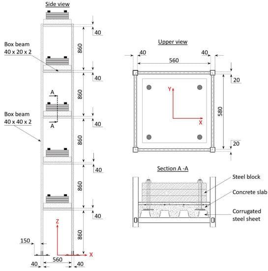
Figure 1.
Reference structure, layout, and main dimensions (mm).

Table 1.
Inertial properties of the floors.
The structure considered was subjected to a monodirectional seismic acceleration (aY) along the Y-axis of the reference system that is reported in Figure 1. The time history of the ay was taken from [22], which refers to the earthquake accelerograms that are compliant with Eurocode 8 [23], and which are related to Zone 3, Ground Type A, and a peak ground acceleration (PGA) equal to 1.23 m/s2 (Figure 2, left side). The zone’s category, ground type, and PGA were selected by considering the recent earthquake history and the typical geological characteristics of the seismic regions in Southern Italy. To coherently apply the real earthquake accelerogram to the scaled structure, the acceleration time history was adjusted by scaling the time vector by the factor (); the scaled time history of the seismic acceleration is reported on the right side of Figure 2 and is hereafter referred to as the “seismic excitation” (ay(t)).
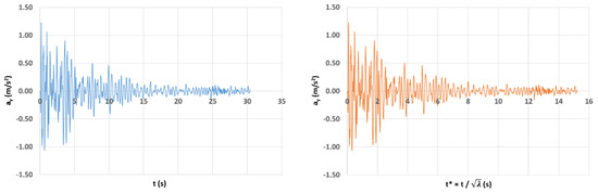
Figure 2.
Seismic acceleration vs. time: real earthquake accelerogram (left); scaled accelerogram (right).
3. Seismic Response of the Reference Structure and Mitigation Target
A finite element model of the reference structure was generated in the UGS-FEMAP® environment [24]. The mesh geometry and the relevant data are reported in Figure 3.
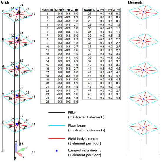
Figure 3.
Finite element model of the reference structure, grids, and elements.
Linear bar elements were used for the mesh of the pillars (one single element per structural item) and horizontal beams (two elements per structural item), while each floor was modeled as a rigid body. To implement the rigid-body condition, auxiliary nodes were generated at the center of each floor and were then rigidly connected to all the nodes of the horizontal beams that support the floor; in these rigid connections, the degrees of freedom of the floor-beam grids were slaved to those of the auxiliary nodes at the center of the floors.
The central floor nodes were also used to define the inertial properties of each floor by means of lumped mass elements.
The grids at the base of the model (Grids 1, 7, 13, and 19) were constrained in all six degrees of freedom, and a modal analysis was launched in the NX-Nastran environment to evaluate the first 10 normal modes of the structure, together with their natural frequencies and generalized masses.
The Lanczos method [25] was selected for the calculation of the first twenty modes and related parameters (frequency and generalized mass); the obtained results are recapped in Table 2 and Figure 4 with reference to the first ten modes only.
Table 2.
Modal parameters of the reference structure (first 10 modes only).
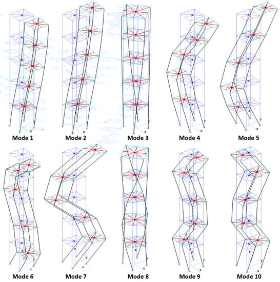
Figure 4.
First 10 modes of the reference structure.
The modal database of the reference structure and the earthquake accelerogram (ay(t)) were given as the input to a set of in-house developed MATLAB® [26] routines that implement the formulation that is described in Appendix A for the evaluation of the seismic response of the structure. A viscous modal damping of 0.015 (typical value for metallic structures, [27]) was considered for all modes.
Only the first six modes that were characterized by displacements along the direction of excitation (Modes 2,3,5,7,8,10) were taken into account since the residual inertia associated with all the remaining modes was equal to only 2% of the overall inertia that was exhibited by the structure when moving along the y-axis. The definition of “residual inertia” and the explanation of its link to the number of selected modes are given in Appendix A.
The response of the structure is synthesized here in terms of the time histories of the following parameters:
- -
- The floor acceleration, which is intended as the acceleration (yj) of the j-th floor (j = 1,2, …, 5) with respect to the ground and along the direction of the excitation (y-axis);
- -
- The interstory acceleration/speed, which is intended as the difference (Δyj(/Δyj)) between the acceleration (speed) of the j-th and (j − 1)-th floor (j = 1,2,…,5). When j = 1, the interstory acceleration/speed coincides with the first floor’s acceleration (speed) with respect to the ground.
The obtained time histories are plotted in Figure 5, Figure 6, Figure 7, Figure 8, Figure 9, Figure 10, Figure 11, Figure 12, Figure 13, Figure 14, Figure 15, Figure 16, Figure 17, Figure 18 and Figure 19, while the peak values of the relevant parameters (yj, Δyj, Δyj (j = 1,2, …, 5)) are recapped in Table 3.
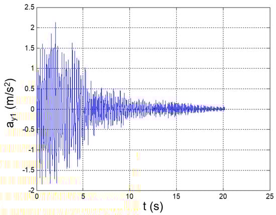
Figure 5.
Seismic response, 1st-floor acceleration (Node 45) with respect to the ground.
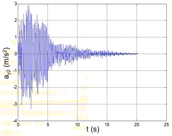
Figure 6.
Seismic response, 2nd-floor acceleration (Node 46) with respect to the ground.
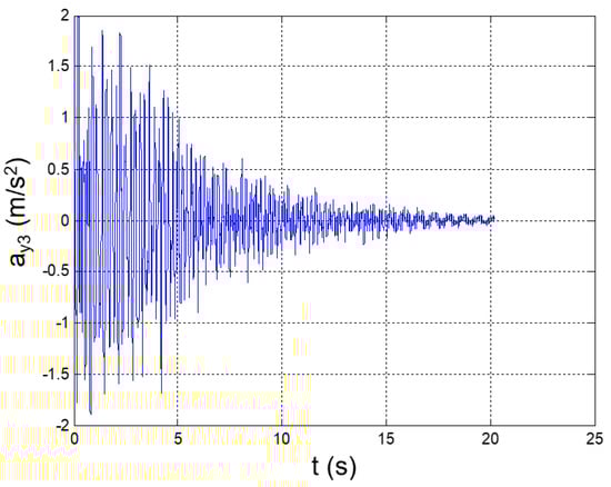
Figure 7.
Seismic response, 3rd-floor acceleration (Node 47) with respect to the ground.
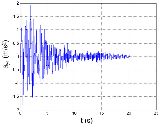
Figure 8.
Seismic response, 4th-floor acceleration (Node 48) with respect to the ground.
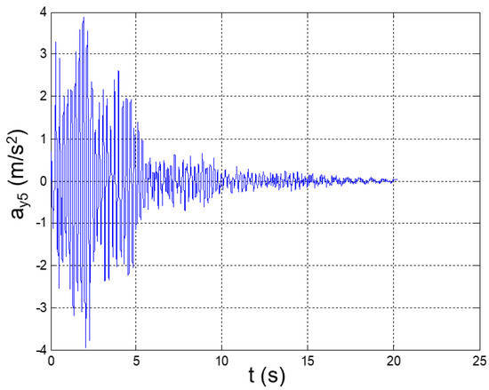
Figure 9.
Seismic response, 5th-floor acceleration (Node 49) with respect to the ground.
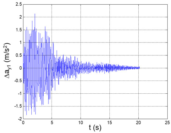
Figure 10.
Seismic response, interstory acceleration at the 1st floor (Δy1 = y1).
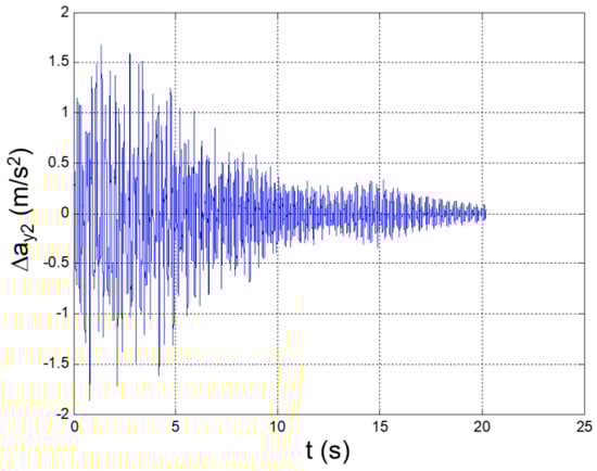
Figure 11.
Seismic response, interstory acceleration at the 2nd floor (Δy2 = y2 − y1).
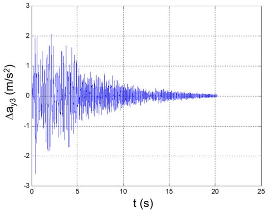
Figure 12.
Seismic response, interstory acceleration at the 3rd floor (Δy3 = y3 − y2).
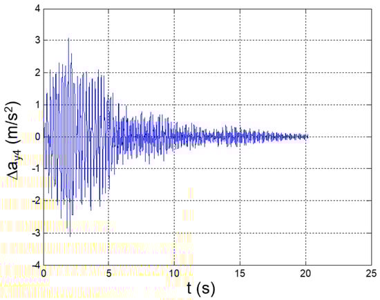
Figure 13.
Seismic response, interstory acceleration at the 4th floor (Δy4 = y4 − y3).
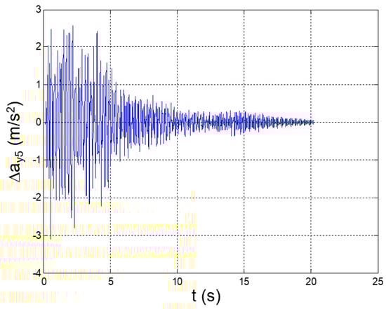
Figure 14.
Seismic response, interstory acceleration at the 5th floor (Δy5 = y5 − y4).
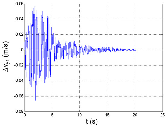
Figure 15.
Seismic response, interstory speed at the 1st floor (Δy1 = y1: speed of Node 45 with respect to the ground).
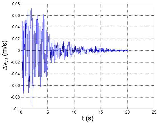
Figure 16.
Seismic response, interstory speed at the 2nd floor (Δy2 = y2 − y1).
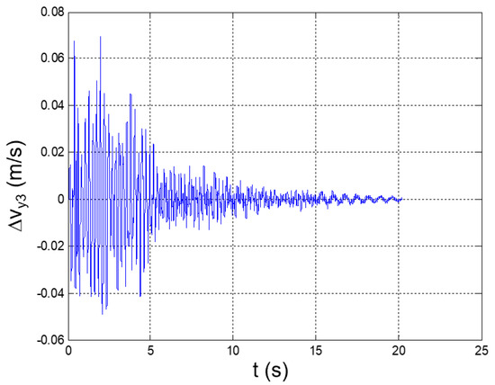
Figure 17.
Seismic response, interstory speed at the 3rd floor (Δy3 = y3 − y2).
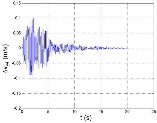
Figure 18.
Seismic response, interstory speed at the 4th floor (Δy4 = y4 − y3).
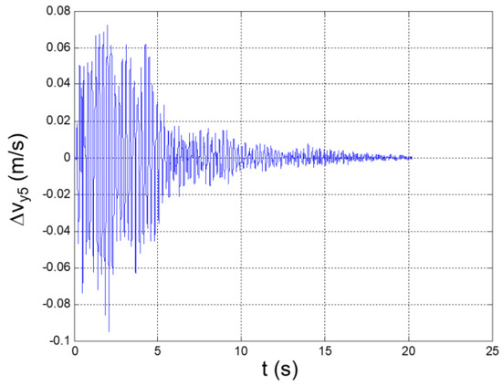
Figure 19.
Seismic response, interstory speed at the 5th floor (Δy5 = y5 − y4).
Table 3.
Seismic response of the reference structure; peak values of relevant parameters (maximum and minimum values in bold).
The maximum and minimum values of the floor accelerations and the interstory accelerations (speeds) occurred at the fifth and fourth floors, respectively. This fully agrees with the typical dynamics of slender buildings, where the highest earthquake-induced accelerations and speeds are generally registered at the top floors [28]. A relevant acceleration peak also occurs at the second floor; this circumstance is justifiable on the basis of the high participation of the second bending mode in the YZ plane in the dynamic response of the structure.
In addition, the maximum floor acceleration is 3.4-fold greater than the peak ground acceleration, which thus shows how relevant the amplification factor of the seismic response could be in the case of predominantly vertical constructions that are sustained by metallic trusses.
For this type of construction, even a moderate earthquake may produce devastating effects; therefore, the adoption of vibration dampers is recommended in order to efficiently mitigate the seismic response.
In this study, a 50% reduction in the acceleration-response peaks at each floor was set as a challenging target for designing a vibration-suppression system (VSS) based on dissipative structural bracings that integrate magnetorheological fluids dampers (MRD) that are available on the market.
In the next section, the theoretical approach that is adopted for the definition of the VSS is discussed.
4. Vibration-Suppression-System Layout and Individuation of the Appropriate MRD
The adoption of dissipative bracings that integrate magnetorheological fluid dampers (MRDs) was considered as a simple and effective solution to mitigate the seismic response of the reference structure.
The bracings were positioned according to the layout in Figure 20, which is in compliance with three practical design requirements:
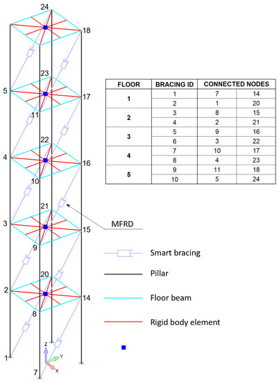
Figure 20.
FEM of the reference structure equipped with the vibration-suppression system.
- To use the lowest number of bracings per floor;
- To preserve the symmetry of the structure with respect to the Y–Z plane (thus preventing relevant changes in its seismic response after the installation of the bracings);
- To dampen the vibrations of the structure along the direction of excitation (Y-axis).
The selection of the best candidate among the MRD models that are available on the market resulted from the qualitative analysis of the acceleration-response spectrum to the seismic signal (Figure 21).
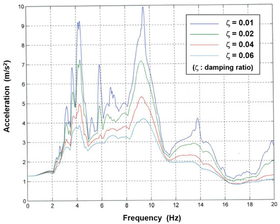
Figure 21.
Acceleration-response spectrum to the seismic signal.
The spectrum is a graphical representation of the transient acceleration input, in terms of how a single-degree-of-freedom (SDOF) system (such as a mass on a spring and a damper) would respond to that input. The horizontal axis shows the natural frequency of a hypothetical SDOF. The vertical axis shows the peak acceleration that this SDOF would undergo as a consequence of the input signal and in correspondence with different damping levels [29].
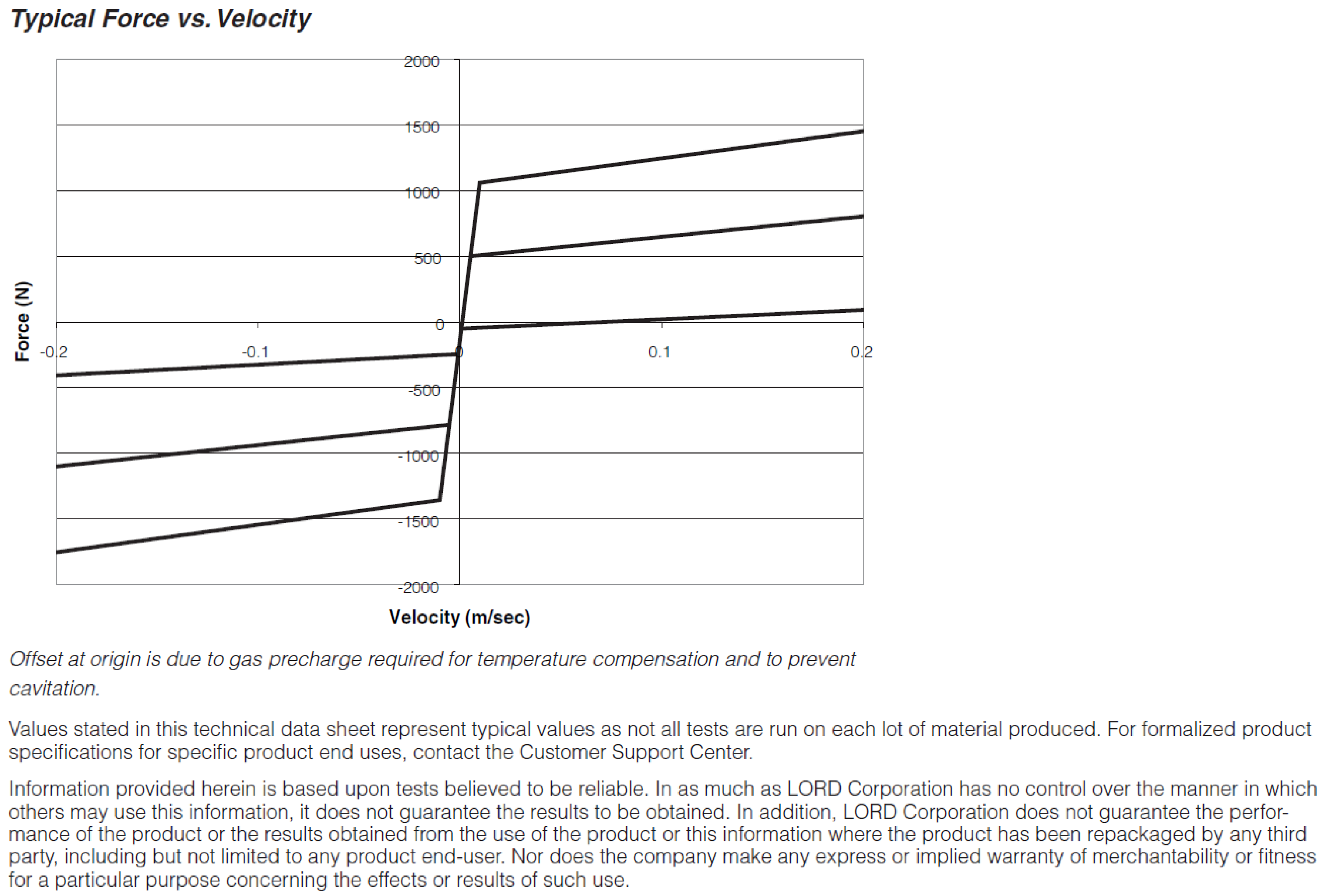
From the curves in Figure 21, it was found that, to mitigate the acceleration response by 50%, it would have been necessary to reach at least a value of 0.04 for the modal damping of all the modes participating in the response. A generalized damping matrix characterized by 4% modal damping for all modes was then assumed for the structure and was converted into physical coordinates. The result was found to be consistent with the expression of the damping matrix that was obtained by assembling the contributions of the linear viscous dampers installed on each bracing, with each one characterized by a damping coefficient in the order of 105 Ns/m. The MRD-1005-3 from Lord Co.® (Cary, NC, USA) proved to ensure equivalent damping right in the order of 105 Ns/m, and it was therefore selected as a suitable device for the specific application (Figure 22; see datasheet in Appendix B). The equivalent physical damping is intended here as the damping (Ceq) that is exhibited by a linear viscous damper that dissipates the same energy as the MRD during the seismic event. The evaluation of this parameter can be carried out by means of the following approach.
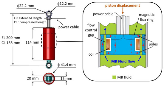
Figure 22.
LORD MRD-1005-3: main dimensions and sketch of the working principle.
The damping force (D) produced by an MRD is a nonlinear function (f) of the piston speed (: ). If we linearize this function by approximating it to Deq, then the quadratic error that arises is:
The quadratic error that is due to the linearization is minimal along the entire duration (T) of the seismic event if Equation (2) is satisfied:
By substituting the expression of from Equation (1) into Equation (2), we obtain:
and, hence:
For the generic MRD-connecting nodes (h and k) of the structure, the order of magnitude of the equivalent damping was calculated by means of Equation (3), and by considering: , where Vk(t)(/Vh(t)) is the speed response of the node (k(/h)) along the direction (kh) to the seismic signal exciting the reference (clean) structure and under the hypothesis of 4% modal damping for all the modes taken into account.
5. MRD Activation Current and Evaluation of the Mitigated Seismic Response of the Structure
As in the case of the oleopneumatic dampers, the energy that is dissipated by an MRD is due to the work that is performed by the forces that act on a piston that slides into a viscous fluid. These forces mainly depend on the piston speed, and the graphical representation of this dependence is generally referred to as the “operative curve of the damper”. The substantial difference between oleopneumatic dampers and MRDs is not only in terms of the different trends of the operative curves but is also in terms of the fact that MRDs can operate along several curves.
The operative curve of an oleopneumatic damper is unique and it depends on the device’s geometry and the mechanical properties of the damping fluid.
The same also applies to an MRD, but, in this case, the mechanical properties of the magnetorheological (MR) fluid can be modified by the magnetic field that is generated by an embedded electromagnet.
In more detail, during the motion of the piston, the MR fluid is forced to flow into tight gaps that are hosted by the piston’s head (Figure 22). When the MRD is powered on, the electric current flows into a solenoid that is installed in the piston’s head, and a magnetic field arises within the gaps. The ferromagnetic particles that are suspended in the MR fluid align themselves to the magnetic field and generate a system of microscopic structures (fibrils) that hamper the MR fluid’s flow through the gaps [30].
At a macroscopic level, this increases the force that is exhibited by the damper, which depends on the intensity of the magnetic field and, consequently, on the intensity of the current into the solenoid. Therefore, different activation currents are associated with different working modes of the MRD and with different operative curves.
The operative curves of the selected MRD are reported in Figure 23 [31] and they correspond with three relevant intensities of the activation current: 0 A (no activation), 1 A (maximum intensity), and 0.5 A (medium intensity).
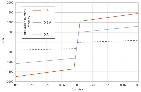
Figure 23.
LORD MRD-1005-3, relevant operative curves.
The seismic response of the structure was evaluated in conjunction with different activation levels of the MRDs, starting from 0 A, and increasing by 0.25 A until the mitigation target of the VSS was reached (Figure 24). At each step, the activation current was equal for all the MRDs in order to preserve the structural symmetry with respect to the Y–Z plane.
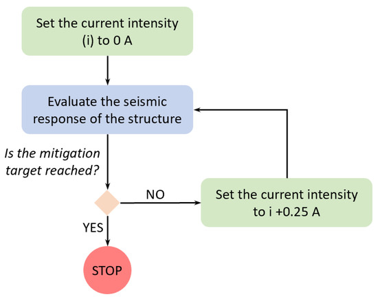
Figure 24.
Calculation loop for the individuation of the activation current compliant with the vibration-mitigation target (defined in Section 3).
Each MRD was treated as a linear damper that was characterized by a specific (equivalent) damping coefficient. Under this assumption, the differential equation that governs the seismic response of the system is linear and takes the form (see Appendix A):
where:
- is the mass matrix of the structure;
- is the stiffness matrix of the structure that is constrained at its base;
- is the damping matrix of the structure, the elements of which are related to the equivalent damping coefficients that are assumed for the MRDs;
- is the displacement vector of the nodes of the structure with respect to the base of the structure;
- is the seismic acceleration at the base of the structure;
- is the vector that defines the direction of the seismic acceleration into the same reference frame that is used for the definition of , , , and .
Equation (4) was solved by referring to the same methodology that was adopted for the evaluation of the seismic response of the structure without dampers: by relying upon the formulation reported in Appendix A, the response was first evaluated in the generalized coordinates domain, and then in terms of the acceleration and speed of the nodes with respect to the base of the structure.
It is worth noting that, in the generalized coordinates domain, the equation that was used to evaluate the seismic response of the structure that was equipped with dampers is formally the same as that used in the case where no dampers were installed. The only difference is in the elements of the generalized damping matrix.
In the case of dampers not being installed on the structure, the generalized damping matrix was built coherently to a modal damping equal to 0.015 for all the relevant modes involved in the seismic response. In the presence of dampers, this matrix is instead given by: , where is the modal matrix.
The damping matrix () was assembled on the basis of the equivalent damping that was exhibited by each MRD, and was calculated by means of the following iterative method (Figure 25):
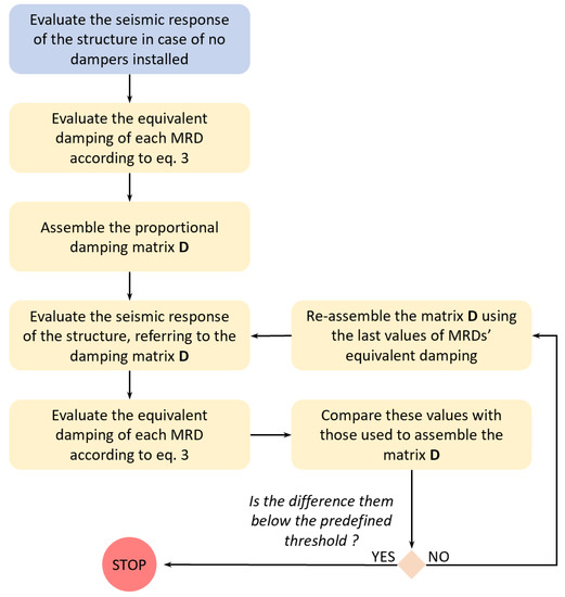
Figure 25.
Iterative method for the calculation of MRDs’ equivalent damping.
Step 1: The seismic response of the structure is evaluated in the case of no dampers installed (clean structure). For the generic MRD to be placed on the i-th bracing that connects the nodes (h and k), the equivalent damping (Deq,i) was found according to Equation (3) and considering:
, where and are the speed responses of the nodes, h and k, respectively, along the h–k direction; the function (f) is coincident with the operative curve of the damper that corresponds to the selected activation current; T is equal to the duration of the seismic event.
Step 2: The seismic response of the structure is evaluated in the case of an MRD that is installed and that exhibits the values of the equivalent damping that was found in the previous step.
Step 3: The equivalent damping of the MRDs is recalculated on the basis of the speed responses () that were evaluated in the previous step.
For each MRD, the new value of the equivalent damping, , is compared to that assumed at the previous step by evaluating the error margin, . If m is below a predefined threshold (t), the process stops, as well as the mitigated seismic response of the structure that is evaluated in the current step.
If not, Steps 2 and 3 are repeated until m < t for each MRD.
The above-described iteration was executed at the second step of the loop in Figure 24 in order to evaluate the mitigated seismic response of the structure and the equivalent damping of the MRDs that corresponded to the input value of the activation current.
The mitigation target for the seismic-induced vibrations was reached in the case of all MRDs activated with a current of 0.5 A; the convergence on the equivalent damping was reached after one iteration only, with a precision threshold of t = 0.001.
The values of the equivalent damping obtained at each step are reported in Table 4. The mitigated seismic response of the structure is plotted in Figure 26, Figure 27, Figure 28, Figure 29, Figure 30, Figure 31, Figure 32, Figure 33, Figure 34, Figure 35, Figure 36, Figure 37, Figure 38, Figure 39 and Figure 40, for the time histories of the floor accelerations with respect to the base, the interstory accelerations, and the speeds. The unmitigated seismic response is also plotted for comparison.
Table 4.
Equivalent damping values for the MRD activated with a current of 0.5 A.
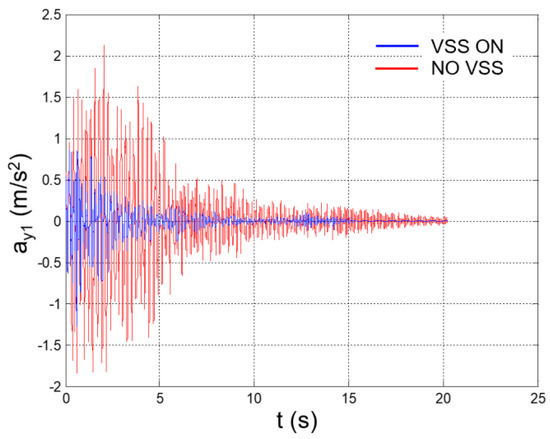
Figure 26.
Seismic response, 1st-floor acceleration (Node 45) with respect to the ground.
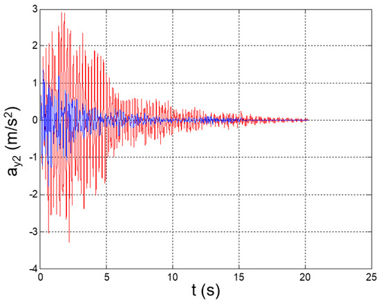
Figure 27.
Seismic response, 2nd-floor acceleration (Node 46) with respect to the ground.
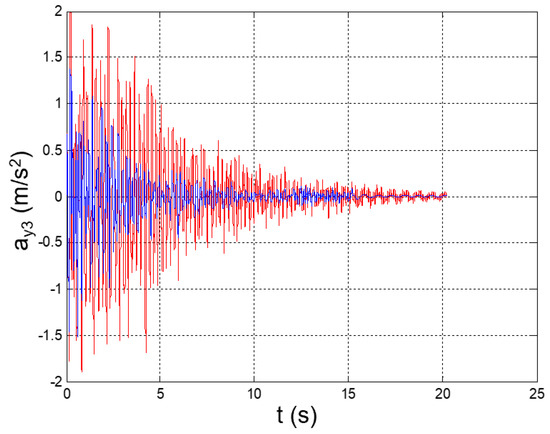
Figure 28.
Seismic response, 3rd-floor acceleration (Node 47) with respect to the ground.
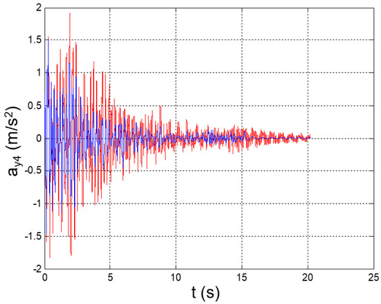
Figure 29.
Seismic response, 4th-floor acceleration (Node 48) with respect to the ground.
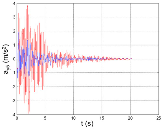
Figure 30.
Seismic response, 5th-floor acceleration (Node 49) with respect to the ground.
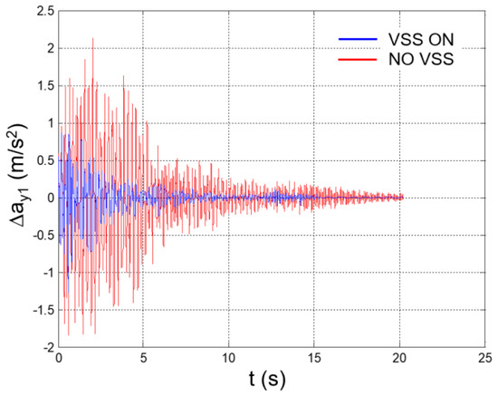
Figure 31.
Seismic response, interstory acceleration at the 1st floor (Δy1 = y1).
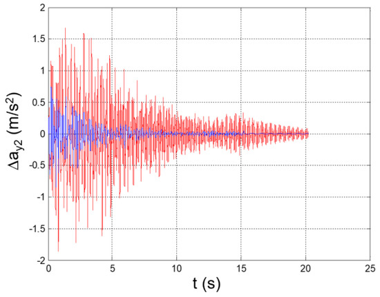
Figure 32.
Seismic response, interstory acceleration at the 2nd floor (Δy2 = y2 − y1).
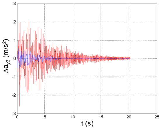
Figure 33.
Seismic response, interstory acceleration at the 3rd floor (Δy3 = y3 − y2).
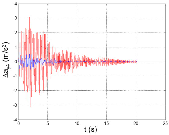
Figure 34.
Seismic response, interstory acceleration at the 4th floor (Δy4 = y4 − y3).
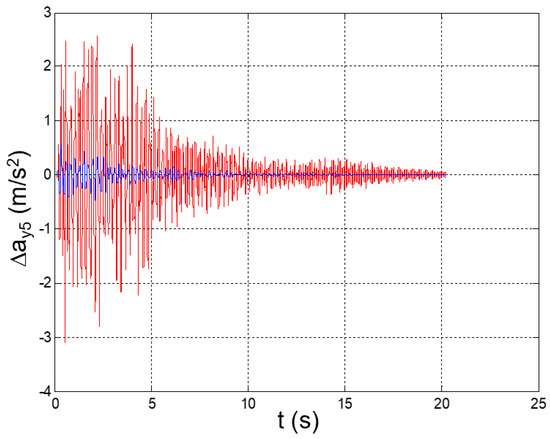
Figure 35.
Seismic response, interstory acceleration at the 5th floor (Δy5 = y5 − y4).
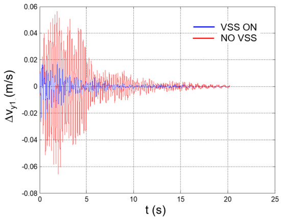
Figure 36.
Seismic response, interstory speed at the 1st floor (Δy1 = y1: speed of Node 45 with respect to the ground).
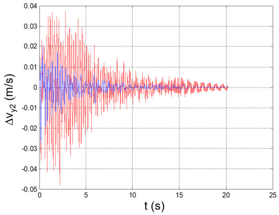
Figure 37.
Seismic response, interstory speed at the 2nd floor (Δy2 = y2 − y1).
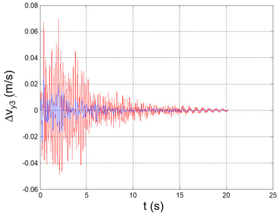
Figure 38.
Seismic response, interstory speed at the 3rd floor (Δy3 = y3 − y2).
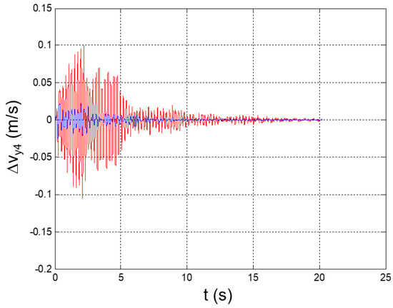
Figure 39.
Seismic response, interstory speed at the 4th floor (Δy4 = y4 − y3).
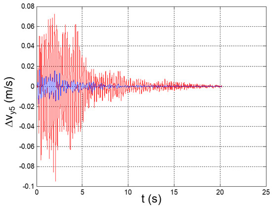
Figure 40.
Seismic response, interstory speed at the 5th floor (Δy5 = y5 − y4).
Peak values of the plotted parameters are recapped in Table 5, together with the achieved mitigation coefficients.
Table 5.
Seismic response of the reference structure, peak values of the relevant parameters, and mitigation coefficients.
6. Experimental Validation of the Vibration-Suppression System (VSS)
The efficacy of the vibration-suppression system was proven by means of true-scale experimental tests that were carried out at the structural dynamics laboratories of the ENEA Casaccia Research Center (Rome, Italy) [32].
The reference structure was installed on a shaking table, which reproduced the accelerogram of the earthquake that was considered for the VSS design.
Three test cases were addressed:
- Test 1: Earthquake striking the clean structure (intended as the reference structure without MRDs installed);
- Test 2: Earthquake striking the structure with selected MRDs (LORD MRD-1005-3) that were installed and not activated;
- Test 3: Earthquake striking the structure with selected MRDs that were installed and activated by a current of 0.5 A.
For each test case, the seismic response of the structure was acquired through five monaxial accelerometers that were installed at the center of each floor and oriented along the direction of the excitation (Figure 41).
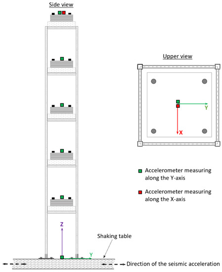
Figure 41.
Accelerometers’ location and type.
Two extra-accelerometers were placed at the base and on the top of the structure. The accelerometer at the base measured along the direction of excitation and was used to check the coherence of the ground acceleration with the reference seismic accelerogram. The accelerometer at the top of the structure was oriented perpendicularly to the symmetry plane of the structure and was used to verify the absence of significant out-of-plane accelerations.
Siemens LMS SCADAS mobile® was used to drive the shaking table and to record the accelerometers’ signals. The input signal generation (shaking-table acceleration) and acquisition processes were controlled and synchronized via LMS Test-Lab software [33].
Each dissipative bracing was realized by joining two squared steel pipes at the ends of the MRD. Hinged joints, which were implemented by means of pin and bolts, were used to connect the MRD to the pipes and the pipes to the structure (Figure 42).
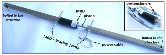
Figure 42.
Dissipative bracing that integrates the MRD.
Manual pretensioners were used to set the initial stroke of the MRD’s piston at half of its maximum value, which thus allowed for equal maximum excursions of the piston in both compression and tension. The pretensioners were removed after the installation of the bracings on the structure.
In Figure 43, the layout of the reference structure with all dissipative bracing installed is reported.
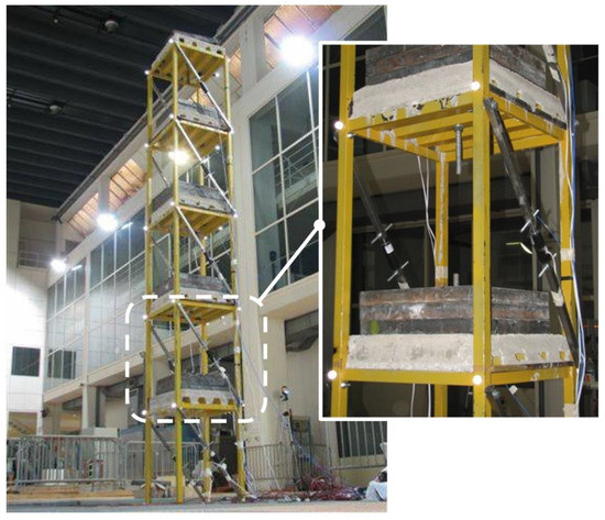
Figure 43.
Reference structure and dissipative bracings (VSS).
The intensity of the electric current into each MRD was regulated by using the potentiometers that were provided by the MRDs supplier (see Appendix B for details).
In Figure 44, Figure 45, Figure 46, Figure 47 and Figure 48, the time histories of the floor accelerations that were recorded during the three test cases are reported. The interstory accelerations were obtained by the elaboration of these measurements and they are plotted in Figure 49, Figure 50, Figure 51, Figure 52 and Figure 53. In all the test cases, the extra-accelerometer placed at the top of the structure showed the absence of accelerations out of the symmetry plane of the structure.
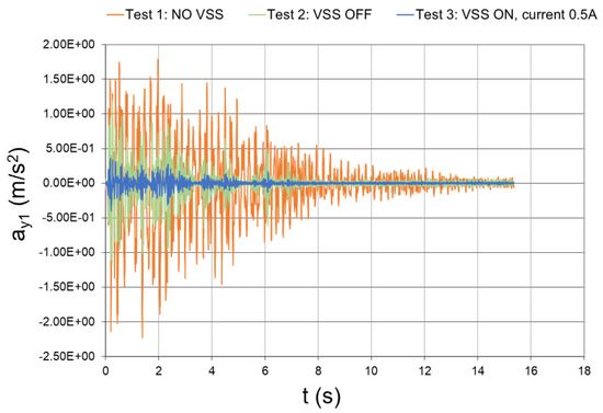
Figure 44.
Seismic response, 1st-floor acceleration with respect to the ground (experimental data).
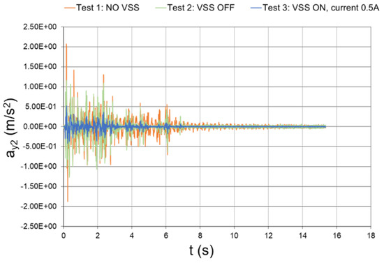
Figure 45.
Seismic response, 2nd-floor acceleration with respect to the ground (experimental data).
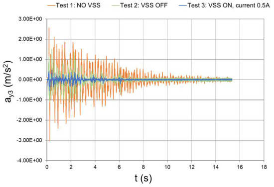
Figure 46.
Seismic response, 3rd-floor acceleration with respect to the ground (experimental data).
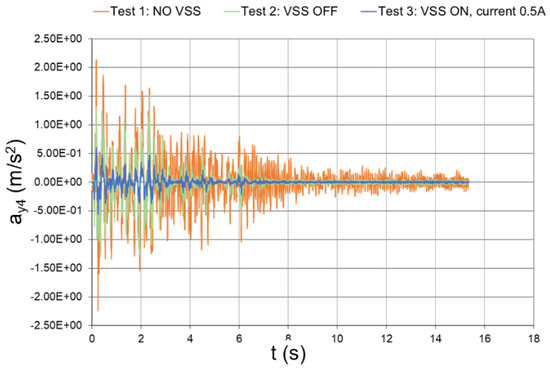
Figure 47.
Seismic response, 4th-floor acceleration with respect to the ground (experimental data).
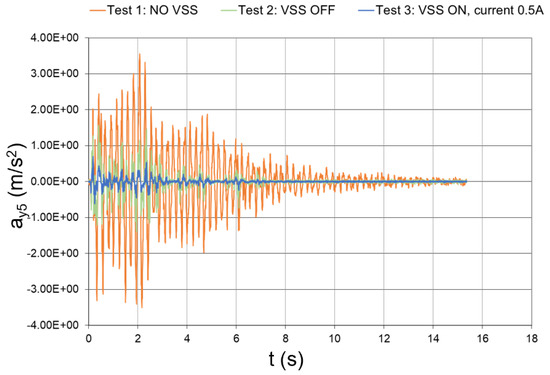
Figure 48.
Seismic response, 5th-floor acceleration with respect to the ground (experimental data).
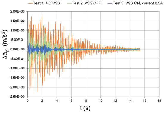
Figure 49.
Seismic response (experimental data), interstory acceleration at the 1st floor (Δy1 = y1).
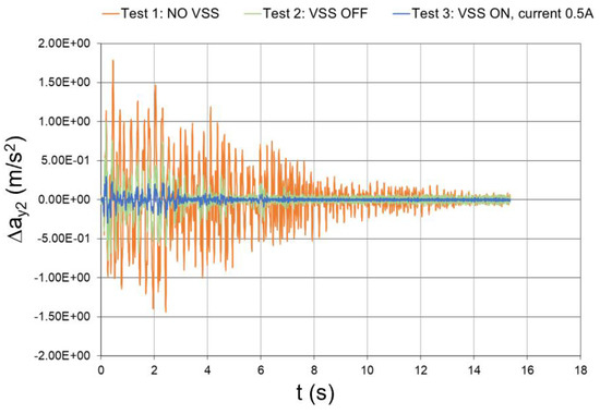
Figure 50.
Seismic response (experimental data), interstory acceleration at the 2nd floor (Δy2 = y2 − y1).
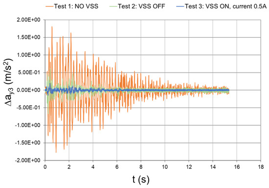
Figure 51.
Seismic response (experimental data), interstory acceleration at the 3rd floor (Δy3 = y3y2 − y2).
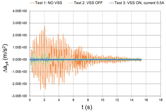
Figure 52.
Seismic response (experimental data), interstory acceleration at the 4th floor (Δy4 = y4y2 − y3).
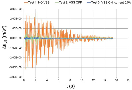
Figure 53.
Seismic response (experimental data), interstory acceleration at the 5th floor (Δy5 = y5y2 − y4).
The peak values of the floor and interstory accelerations are reported in Table 6, together with the mitigation coefficients that were obtained with inactivated and activated dampers. In the case of activated dampers, the mitigation coefficients were even higher than those numerically predicted, which thus proves the effectiveness of the conceived vibration-suppression system.
Table 6.
Seismic response of the reference structure, peak values of the relevant parameters, and mitigation coefficients (experimental data).
7. Conclusions
A practical design was proposed for a seismic protection system that is suitable for slender metallic frames and that is based on dissipative bracings that integrate MRD dampers.
The nonlinear relationship between the dissipative force and the piston speed of the MRD was replaced by a linear equation that involves the evaluation of an equivalent damping coefficient for the MRD. A rational method was adopted for the calculation of the equivalent damping coefficient by assimilating the MRD to a proportional damper that dissipated the same amount of energy during the seismic event.
The linearization of the dynamic behavior of the magnetorheological fluid dampers allowed for the implementation of a robust iterative process for the evaluation of the seismic response of the structure in correspondence with the different activation levels of the embedded MRDs. The response was first evaluated in the generalized coordinates domain, and then in terms of the acceleration and speed of the structural nodes with respect to the base of the structure. A current intensity of 0.5 A was found to be adequate to achieve the target 50% reduction in the acceleration-response peaks at each floor.
A true-scale model of the reference structure was then manufactured and installed on a shaking table, which provided the reference seismic excitation. The acceleration response was measured at each floor of the structure in three operative conditions: (1) A clean structure (no dissipative bracings installed); (2) With the vibration-suppression system off (dissipative bracings installed and MRD not activated); (3) With the vibration-suppression system on (dissipative bracings installed and MRD activated by a current of 0.5 A).
With respect to the “clean structure” case, the activation of the MRD led to an average reduction of nearly 70% for the peaks of the floor accelerations with respect to the base of the structure, as well as for the interstory accelerations. The higher level of abatement with respect to the design target can be justified by considering the intrinsic limitations of the numerical simulations that did not take into account the extra damping that was due to the friction between the structural elements at their interface joints. A slight increase in the modal damping of the clean structure with respect to the assumed value (1.5% for all modes) would have surely limited the discrepancy between the numerical expectations and the experimental outcomes. On the other hand, the proposed simulation strategy is mainly intended to provide a fast and practical tool for the robust design of the seismic mitigation system; in light of this consideration, any simplification is acceptable if it results in the safer design of the system.
The robustness and effectiveness of the conceived system are further proven by the recorded seismic response of the structure in the case of MRDs being installed and inactivated. The average reduction factor for the floor acceleration peaks and for the interstory acceleration peaks is nearly 48%, even if some floors have a reduction factor lower than 50%. This means that, even in the case of a blackout (highly probable during an earthquake) or the malfunction of the hardware that powers the MRDs, the system still maintains good abilities to dampen the structural response to the seismic excitation.
The achievement of significant vibration-suppression levels in the case of both activated and nonactivated devices represents a remarkable result, which shows not only the effectiveness of MRDs, but also the soundness of the design and simulation approaches that were adopted for the assessment of the seismic protection system’s dynamics.
Funding
Part of the research described in this paper has been carried out within the framework of the Tellus Stability Project, which was funded by the Italian Ministry of Research, Instruction and University, in the framework of the FAR platform, and pursuant to Article 5 of Ministerial Decree No. 593/2000.
Institutional Review Board Statement
Not applicable.
Informed Consent Statement
Not applicable.
Data Availability Statement
All the relevant data used in this study have been declared in the paper’s main text. Further data may be requested from the corresponding author.
Acknowledgments
The author would like to thank the staff of the ENEA-Casaccia research center for the extraordinary support for all the experimental activities that were aimed at the characterization of the seismic response of the reference structure.
Conflicts of Interest
The author declares no conflict of interest. The funders had no role in the design of the study; in the collection, analyses, or interpretation of data; in the writing of the manuscript, or in the decision to publish the results.
Nomenclature
| ay | seismic acceleration (along the Y-axis of the reference system in Figure 1) |
| ayj | acceleration (along the Y-axis) of the j-th floor with respect to the ground |
| ayj,max | maximum value of ayj |
| ayj,min | minimum value of ayj |
| damping matrix of the structure in the case of MRD installed | |
| displacement vector of the nodes of the structure with respect to its base | |
| Deq,i | equivalent damping of the i-th bracing |
| seismic acceleration at the base of the structure | |
| excitation direction | |
| ID | identification (number) |
| stiffness matrix of the structure constrained at its base | |
| generalized stiffness matrix | |
| mass matrix of the structure | |
| generalized mass matrix | |
| MRD(s) | magnetorheological fluid damper(s) |
| MRF | magnetorheological fluids |
| PGA | peak ground acceleration |
| generalized displacement vector | |
| SDOF | single degree of freedom |
| T | duration of the seismic event |
| t | time variable |
| VSS | vibration-suppression system |
| vyj | speed (along the Y-axis) of the j-th floor with respect to the ground |
| vyj,max | maximum value of vyj |
| vyj,min | minimum value of vyj |
| Δayj | interstory acceleration between the j-th and the (j – 1)th floors (Δayj = ayj − ay(j−1)) |
| Δayj,max | maximum value of Δayj |
| Δayj,min | minimum value of Δayj |
| ΔVi | relative speed between the nodes connecting the i-th bracing taken along the axis of the bracing |
| Δvyj | interstory speed between the j-th and the (j – 1)th floors (Δvyj = vyj − vy(j − 1)) |
| Δvyj,max | maximum value of Δvyj |
| Δvyj,min | minimum value of Δvyj |
| Greek symbols | |
| ε2 | quadratic error |
| modal matrix | |
| vector of the modal participation factors | |
| λ | geometrical scale factor of the reference structure |
| μ | error margin |
| damping matrix of the reference structure (no dampers installed) | |
| γ | generalized damping matrix |
| τ | precision threshold |
| pulsation of the i-th mode | |
| ζ | damping ratio |
Appendix A. Formulation Adopted for the Evaluation of the Seismic Response and the Residual Inertia Criterion
Let us call S a generic structure that is fixed to the ground. Let IB be the subset of the structural nodes that belong to the base of S, with IS being the subset of the remaining nodes of S, and B being an extra node to which all the nodes of the base are rigidly linked (BIS, BIB). Referring to a Cartesian system (
(O,XYZ)), which is fixed with respect to the ground, if a forced displacement (db) is imposed on B along the direction K, then, the In,S nodes will all move by db in the same direction. In mathematical terms, if N is the number of active degrees of freedom of the In,S nodes, the displacement d of the ISnodes will be equal to db·e, where e is the (N × 1) vector that is characterized by unitary components in terms of the positions associated with the K direction, and by zero components in all the other positions To clarify this with an example, let us suppose that IS is characterized by eight nodes, and that each of the nodes has two active degrees of freedom that are related to the translations along the X and Y axis of a given reference frame (N = 16). In this case, if the displacement (db) is imposed along the X direction, then the vector (e) would have the following expression:
In the absence of external forces and dissipation, the dynamic response of S to an acceleration that is imposed at its base is governed by the following equation:
where:
- me is the inertia of the base of S along the displacement direction that is individuated by the vector, e;
- is the mass matrix of S related to the In,S nodes only;
- is the stiffness matrix of S constrained at its base;
- d is the displacement vector of the In,S nodes.
Let be the displacement vector of the IS nodes with respect to a reference system (’ (O’, X’Y’Z’)), moving together with the base of S and having the axes X’, Y’, and Z’, which are oriented as X, Y, and Z, respectively. Since it results in , the vector, , can be expressed in the following way:
where is the identity matrix of the size (N).
By substituting Equation (A2) into Equation (A1), we obtain:
or, in a more compact form:
Since is equal to the seismic accelerogram (a(t)), the second part of Equation (A3) can be rewritten as follows:
which allows for the evaluation of the seismic response of the structure (i.e., of the time histories of the displacements ((/speeds /accelerations )) of the IS nodes with respect to the base of S).
In the presence of viscous dissipation, all the considerations made so far may be repeated, which thus leads to the following expression of the equation that governs the seismic response of the structure:
where is the viscous damping matrix of the system and, for the cases of practical interest, is proportional to the stiffness and mass matrixes.
Equation (A5) may be effectively solved in the generalized coordinates domain [34].
If is the matrix of the N modes of the structure constrained to its base, then the vector () may be expressed as the product, , where is the vector of the generalized coordinates of the system.
By placing this expression into Equation (A5), we obtain the following:
and, after pre-multiplying all the terms by the transpose of :
where:
- = is the diagonal matrix of the generalized masses (mG,i (i = 1, …, N));
- = is the diagonal matrix of the generalized masses (mG,i (i = 1, …, N));
- = is the matrix of the generalized damping (sG,i (i = 1, …, N)), which is also diagonal, according to Basile’s hypothesis [34];
- = is the vector of the modal participation factors (Gi (i = 1,...,N)).
Equation (A6) represents a set of decoupled differential linear equations that can be solved individually. The generic equation has the following expression:
and its solution is given by:
where hi(t) is the impulse response function of the i-th generalized coordinate:
where:
- is the natural pulsation of the i-th mode;
- is the modal damping of the i-th mode;
- is the damped pulsation of the i-th mode, which is equal to .
Once the time histories of the generalized coordinates are evaluated, together with their first and second derivatives, the seismic response of the structure can be obtained by recalling that:
The evaluation of the time histories of all the generalized coordinates may, however, represent a demanding task from a computational standpoint, especially when N is significantly large. This is why, in general practice, only a subset of modes (and generalized coordinates) is selected to solve the dynamic equation of the structure with adequate approximation. Clearly, the greater the number of selected modes, the better the level of approximation will be. On the other hand, not all modes make the same contribution to the physical response of the structure, and, after a certain number of modes, the computational effort is not rewarded by a related increase in the results’ precision. The residual inertia criterion represents a powerful tool to individuate the right number of modes to be used for the evaluation of the seismic response with a good level of approximation. The criterion is based on the following identity:
according to which the total inertia of the structure along the direction of excitation () is equal to the sum of the squares of the modal participation factors. This result can be easily demonstrated by observing that the natural modes represent a base of the vector space (N) and, therefore, the vector (e) may be expressed as a sum of its modal components (e1, e2, …, eN):
The components may be determined by invoking the orthogonality of the modal base. If we pre-multiply each member of Equation (A11) by , we obtain:
Since it results in the following:
we know, from Equation (A12), that ; therefore, Equation (A11) may be rewritten as follows:
Equation (A10) may be derived from Equation (A13) by pre-multiplying each member by and then by recalling the orthogonality of the modal base.
If we select only modes for the evaluation of the seismic response of the structure, according to Equation (A10), we consider only a part of the actual inertia of the structure along the direction of excitation:
The level of approximation of the actual seismic response is correlated with the amount of structural inertia that participates in the response; it follows that, the lower the residual inertia, the higher the precision of the obtained results.
For slender metallic structures, such as the one considered in this paper, and irrespective of the direction of excitation (e), the first 5–6 modes generally ensure that the residual inertia is lower than 3% of the actual one, which thus provides a more than satisfactory characterization of the seismic response.
Appendix B. LORD ® MRD-1005-3 Datasheet


References
- Medeot, R. The European Standard on Anti-Seismic Devices. IABSE Symp. Rep. N 2010, 97, 39–46. [Google Scholar]
- Castellano, M.G.; Infanti, S. Recent Applications of Italian anti-seismic devices. WIT Trans. Built Environ. 2009, 104, 333–341. [Google Scholar]
- Nakamura, Y.; Okada, K. Review on seismic isolation and response control methods of buildings in Japan. Geoenviron. Disasters 2019, 6, 1–10. [Google Scholar] [CrossRef]
- Wei, Z.; Xiao-ting, R. Semiactive Vibration Control Using a Magnetorheological Damper and a Magnetorheological Elastomer Based on the Bouc-Wen Model. Shock. Vib. 2014, 2014, 405421. [Google Scholar] [CrossRef] [Green Version]
- Michele Dassisti, M.; Brunetti, G. Introduction to Magnetorheological Fluids. In Encyclopedia of Smart Materials; Olabi, A.-G., Ed.; Elsevier: Amsterdam, The Netherlands, 2022; pp. 187–202. [Google Scholar]
- Zhang, Y.; Zhang, X.S.; Silva, R.P.; Ding, B.; Zhang, P.; Shao, G. Lithium-Sulfur Batteries Meet Electrospinning: Recent Advances and the Key Parameters for High Gravimetric and Volume Energy Density. Adv. Sci. 2022, 9, e2103879. [Google Scholar] [CrossRef] [PubMed]
- Zhang, Y.; Zhang, P.; Zhang, S.; Wang, Z.; Li, N.; Silva, S.R.P.; Shao, G. A flexible metallic TiC nanofiber/vertical graphene 1D/2D heterostructured as active electrocatalyst for advanced Li–S batteries. InfoMat 2021, 3, 790. [Google Scholar] [CrossRef]
- Kerboua, M.; Benguediab, M.; Megnounif, A.; Benrahou, A.H.; Kaoulala, F. Semi Active Control of Civil Structures, Analytical and Numerical Studies. Phys. Procedia 2014, 55, 301–306. [Google Scholar] [CrossRef] [Green Version]
- Qiao, F.; Liu, J.; Dai, J.; Sun, L.; Guo, H. Modelling of MRD and Its Application for Seismic Reduction. In Proceedings of the 2010 International Conference on Modelling, Identification, and Control, Innsbruck, Austria, 17–19 July 2010; pp. 682–687. [Google Scholar]
- Dyke, S.J.; Spencer, B.F.; Sain, M.K.; Carlson, J.D. Modeling and control of magnetorheological dampers for seismic response reduction. Smart Mater. Struct. 1996, 5, 565–575. [Google Scholar] [CrossRef]
- Dyke, S.J.; Spencer, B.F.; Sain, M.K.; Carlson, J.D. Experimental Verification of Semi-Active Structural Control Strategies using Acceleration Feedback. In Proceedings of the 3rd International Conference on Motion and Vibration Control, Chiba, Japan, 1–6 September 1996; pp. 291–296. [Google Scholar]
- Dyke, S.J.; Spencer, B.F. A Comparison of Semi-Active Control Strategies for the MR Damper. In Proceedings of the International Conference on Intelligent Information Systems, Bahama Island, Bahamas, 8–10 December 1997. [Google Scholar]
- Jansen, L.M.; Dyke, S.J. Investigation of Nonlinear Control Strategies for the Implementation of Multiple Magnetorheological Dampers. In Proceedings of the ASCE Engineering Mechanics Conference, Baltimore, MD, USA, 13–16 June 1999. [Google Scholar]
- Ying, Z.G.; Ni, Y.Q.; Ko, J.M. Non-Clipping Optimal Control of Randomly Excited Nonlinear Systems using Semi-Active ER/MR dampers. In Proceedings of the SPIE, Smart Systems and Materials-Smart Systems for Bridges Structures and Highways, the International Society for Optical Engineering, San Diego, CA, USA, 28 June 2002; pp. 209–218. [Google Scholar]
- Zhang, J.; Roschke, P.N. Active control of a tall structure excited by wind. J. Wind. Eng. Ind. Aerodyn. 1999, 83, 209–223. [Google Scholar] [CrossRef]
- Hiemenz, G.J.; Choi, Y.-T.; Wereley, N.M. Seismic Control of Civil Structures Utilizing Semi-Active MR Bracing Systems. In Proceedings of the SPIE, Smart Structures and Materials: Smart Systems for Bridges Structures and Highways, The International Society for Optical Engineering, Newport Beach, CA, USA, 20 April 2000; pp. 217–228. [Google Scholar]
- Li, J.; Samali, B.; Ha, G. Fuzzy Sliding Mode Control of a Five Story Benchmark Model Equipped with Active Mass Driver (AMD). In Proceedings of the 6th International Conference on Motion and Vibration Control, Saitama, Japan, 20–23 August 2002; pp. 172–177. [Google Scholar]
- Ni, Y.Q.; Liu, H.J.; Ko, J.M. Experimental Investigation on Seismic Response Control of Adjacent Buildings using Semi-Active MR Dampers. In Proceedings of the SPIE, Smart Systems and Materials-Smart Systems for Bridges Structures and Highways, the International Society for Optical Engineering, San Diego, CA, USA, 28 June 2002; pp. 334–344. [Google Scholar]
- Xu, Z.D.; Shen, Y.P.; Guo, Y.Q. Semi-active control of structures incorporated with magnetorheological dampers using neural networks. Smart Mater. Struct. 2003, 12, 80–87. [Google Scholar] [CrossRef]
- Kim, S.; Clark, W.W. Fuzzy logic semi-active vibration control. Adapt. Struct. Mater. Syst. 1999, 16424, 367–372. [Google Scholar]
- Alli, H.; Yakut, O. Fuzzy sliding-mode control of structures. Eng. Struct. 2005, 27, 277–284. [Google Scholar] [CrossRef]
- Website of the Consortium of the University Laboratories of Seismic and Structural Engineering. Available online: https://www.reluis.it/ (accessed on 1 March 2022).
- European Commision, Eurocode 8: Design of Structures for Earthquake Resistance; BS EN 1998 SET; European Publication Office. 2006. Available online: https://data.europa.eu/doi/10.2788/91658 (accessed on 1 March 2022).
- Femap® Website. Available online: https://www.plm.automation.siemens.com/ (accessed on 1 March 2022).
- Lanczos, C. An iteration method for the solution of the eigenvalue problem of linear differential and integral operators. J. Res. Natl. Bur. Stand. 1950, 45, 255–282. [Google Scholar] [CrossRef]
- Matlab® Website. Available online: https://www.mathworks.com/ (accessed on 3 February 2022).
- Cremer, L.; Heckl, M. Stucture-Borne Sound; Springer: New York, NY, USA, 1988; Chapter 4. [Google Scholar]
- Saatcioglu, M. High-Rise Buildings in Natural Disaster. In Encyclopedia of Natural Hazards, Encyclopedia of Earth Sciences Series; Bobrowsky, P.T., Ed.; Springer: Dordrecht, The Netherlands, 2013. [Google Scholar]
- Lalanne, C. Mechanical Vibration and Shock Analysis. In Mechanical Shock, 2nd ed.; Wiley: Hoboken, NJ, USA, 2009; Volume 2. [Google Scholar]
- Srinivasan, A.V.; Mc Farland, D.M. Smart Structures, Analysis and Design; Cambridge University Press: Cambridge, UK, 2010; Chapter 4. [Google Scholar]
- LORD® MRD-1005-3 Datasheet. Available online: https://www.lord.com/ (accessed on 2 March 2022).
- ENEA Resarch Center. Available online: https://www.casaccia.enea.it/ (accessed on 2 March 2022).
- Siemens LMS Scadas/Test-Lab®. Available online: https://www.plm.automation.siemens.com/global/it/products/simcenter/scadas.html (accessed on 2 March 2022).
- Girard, A.; Roy, N. Dynamique des Structrues Industrielles; Hermes Science Publications: Paris, France, 2003. [Google Scholar]
Publisher’s Note: MDPI stays neutral with regard to jurisdictional claims in published maps and institutional affiliations. |
© 2022 by the author. Licensee MDPI, Basel, Switzerland. This article is an open access article distributed under the terms and conditions of the Creative Commons Attribution (CC BY) license (https://creativecommons.org/licenses/by/4.0/).