Abstract
A preliminary study is carried out to investigate the aerodynamic characteristics of a square cylinder with Savonius wind turbines and to explain the reason why this kind of structure can suppress wind-induced vibrations. A series of computational fluid dynamics simulations are performed for the square cylinders with stationary and rotating wind turbines at the cylinder corners. The turbine orientation and the turbine rotation speed are two key factors that affect aerodynamic characteristics of the cylinder for the stationary and rotating turbine cases, respectively. The numerical simulation results show that the presence of either the stationary or rotating wind turbines has a significant effect on wind forces acting on the square cylinder. For the stationary wind turbine cases, the mean drag and fluctuating lift coefficients decrease by 37.7% and 90.7%, respectively, when the turbine orientation angle is 45°. For the rotating wind turbine cases, the mean drag and fluctuating lift coefficients decrease by 34.2% and 86.0%, respectively, when the rotation speed is 0.2 times of vortex shedding frequency. Wind turbines installed at the corners of the square cylinder not only enhance structural safety but also exploit wind energy simultaneously.
1. Introduction
Techniques to reduce wind-induced vibration of high-rise buildings have practical significance for ensuring structure safety and occupant comfort. In general, there are two traditional strategies, mechanical strategies and aerodynamic modifications, to reduce wind-induced vibrations. The tuned mass damper (TMD) installed inside tall buildings is one of the most effective mechanical strategies. In order to achieve an ideal vibration control effect, the mass of the damper normally needs to reach about 0.5–3% of the building mass. As a result, the damper not only occupies a large amount of building space, but also requires a stronger structure system to support such a heavy device. Furthermore, aerodynamic modification strategies, including rounding corners [1,2,3] and recessing corners [4,5,6], have also been studied. Wind tunnel model testing results demonstrate that slotted corners and chamfered corners can cause significant reductions in both along-wind and cross-wind responses [7,8]. Drag forces on a cylinder can also be reduced by adding a splitter plate behind it [9]. Although these strategies are very effective, they sacrifice the valuable space of tall buildings for the sole purpose of reduction in wind loading and wind-induced vibrations.
To further achieve the purpose of reducing drag, many researchers use the moving surface boundary layer control method (MSBC) to inject momentum into the flow field to prevent the formation of boundary layers. In [10], experimental research was conducted on the aerodynamic characteristic of a square cylinder under the momentum injection method. The results show that in the presence of MSBC, the drag of the square cylinder is considerably reduced at all angles of attack. In research reported in [11], a rectangular prism with two rotating cylinders was studied in a wind tunnel, and the effects of different rotation speed and modes on the aerodynamic characteristic were analyzed. Previous scholars mainly relied on the rotation of the small cylinder to inject momentum into the flow field. We consider replacing the small cylinder with wind turbines to increase its possibility and value in engineering applications.
Compared to the sole purpose of aerodynamic modification strategies to suppress wind-induced vibrations of tall buildings described in previous studies, it is desirable to develop effective aerodynamic devices for not only suppressing the wind-induced vibrations but also harvesting wind energy. Extensive studies aimed at making wind energy more efficient have also been carried out. The authors of [12] added two small diameter cylindrical rods on both sides of the cylinder to significantly improve the efficiency of a vortex-induced vibration energy collection system. Wind turbines have been installed in various positions of tall buildings, such as rooftop and through opening and channel between two buildings. The authors of [13] used the scale model to evaluate the wind speed amplifications in the tunnels for wind-power generation through the installation of wind turbines. To obtain optimal environmental benefits, the optimizing design of wind turbines installed on the tall buildings is also discussed [14,15]. Because previous studies have only focused on the energy-saving benefits of installing wind turbines on structures, we consider that installation of the wind turbine at the corners of the square cylinder will not only enhance structural safety but also exploit wind energy simultaneously.
This is a preliminary study to investigate the aerodynamic characteristics of a square cylinder with Savonius wind turbines and attempts to explain the reason why this kind of structure can suppress wind-induced vibrations. Numerical models, including numerical method, computational configuration and mesh arrangement, grid size and time step configuration, and simulation cases are illustrated in Section 2. Mean pressure coefficients, force coefficient and vortex shedding, and flow pattern around the cylinders for both stationary and rotating wind turbines are shown in Section 3. Finally, conclusions are summarized in Section 4.
2. Numerical Simulation Configurations
2.1. Numerical Method
RANS [16,17,18] treats the vortices of different scales equally in the flow field and smoothens the details of the temporal and spatial variations in pulsation motion through average operation. The turbulence model we used is the SST .
The continuity equation and momentum equation for impressible flow are expressed as:
where U and P are the averaged velocity and pressure, respectively; shows air density and refers to eddy viscosity; is the Reynolds stress which can be expressed as and is the Kronecker delta.
According to [18,19], the control equations of SST k–ω are expressed as follows:
where ; is turbulent kinetic energy; is the dissipation rate of turbulent kinetic energy; is the velocity component and subscripts i, j = x, y, z; is the term of turbulent kinetic energy generation caused by the velocity gradient; and are the convection terms for and , respectively; and are the effective diffusion terms of and caused by turbulence, respectively; and is the cross-convection term ().
The coefficient of eddy viscosity can be obtained by:
where is the absolute value of vorticity, is a function that is one for boundary-layer flows and zero for free shear layers, and is the empirical coefficient.
The transition from the model near the wall to the model far from the wall is controlled by mixed function F1:
where y is the distance to the next surface, is the eddy viscosity, and is the positive portion of the cross-diffusion term. Model coefficient is 0.856.
The open-source computational fluid dynamics package OpenFOAM is used for numerical simulations in this study. The finite volume method is adopted to solve the unsteady incompressible Navier–Stokes equation. The PIMPLE scheme is used to solve the pressure–velocity coupling. The second order implicit scheme is selected for time discretization. Gauss linear upwind scheme is used for spatial discretization. The time step is set as 1.0 × 10⁻⁶ s. In terms of time step selection, to assess how the size of the time steps may affect the results, three time steps of 2 × 10⁻⁵, 1.0 × 10⁻⁶, and 1.0 × 10⁻⁷ s are tested. At last, 1.0 × 10⁻⁶ s is selected to balance the simulation time and the result accuracy. For all simulations, more than 1000 nondimensional time steps, corresponding to approximately 50 vortex-shedding cycles, which is much larger than the number of vortex-shedding cycles adopted in the previous studies [20,21], are taken for assuring reliable results.
2.2. Computational Configuration and Mesh Arrangement
The 2D computational domain, 92 W long and 25 W wide, is illustrated in Figure 1a in which the width (W) of the cross section is 0.1 m and the cylinder centroid is defined as the origin of the coordinate. The lateral boundary is 12.5 W away from the cylinder centroid in terms of the previous studies [22]. In order to allow flow redevelopment behind the wake region, the distances between the cylinder centroid and the inlet and the outlet boundary are 30.5 W and 61.5 W, respectively.
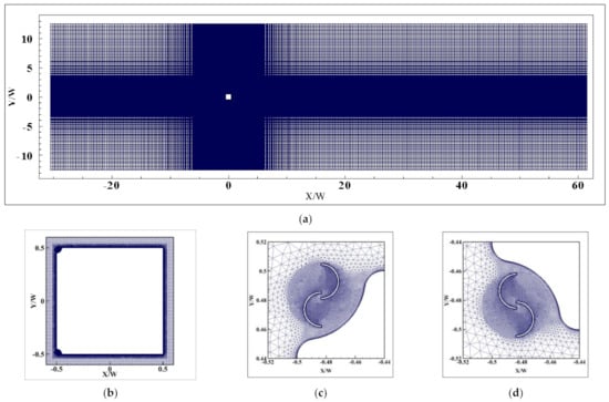
Figure 1.
Views of grids for a square cylinder with wind turbines at two leading corners: (a) Grid distribution in x–y plane; (b) Grid surrounding square cylinder; (c) Grid surrounding upper wind turbine; (d) Grid surrounding lower wind turbine.
As for the boundary conditions, a smooth flow condition with a wind speed of 9 m/s is used at the inlet (, ) and the Reynolds number is 6.0 × 10⁴, which is consistent with that in [22]. At the outlet boundary, a zero static pressure is adopted (, ). Two lateral boundaries are defined as a symmetry boundary condition (, ), which is used to model zero-shear slip walls in viscous flows. An empty condition is enforced on the top and bottom surfaces of the computational domain, which is an ordinary method to solve the 2D problem in OpenFOAM. Two vertical-axis wind turbines are installed at two leading corners of the square cylinder and the nonslip wall boundary condition (, ) is applied to surfaces of the cylinder and the wind turbines, where refers to the normal direction, and represent the velocity components in x and y directions, respectively.
2.3. Grid Size and Time Step Configuration
The hybrid grid scheme is used for discretization, as shown in Figure 1. Because of the geometric irregularity of the wind turbines, an unstructured grid is adopted around the turbines in the vicinity of the cylinder. Structural meshes are used for the whole computational domain except the region containing wind turbines. As shown in Figure 2, the diameter of wind turbines is 5/100 W, d is 7/300 W, and e is 1/240 W, which leads to a ratio (e/d) of 1/6. The height of the minimum grid (δ) is 0.004 mm, the maximum y+ values for all cases is less than 1. The rotation of the wind turbine is implemented via the dynamic grid model, and a pair of coupling interfaces is set between the rotating region and the stationary region.
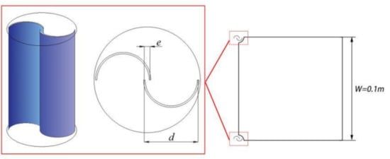
Figure 2.
Sketch of Savonius wind turbines.
In order to consider the influence of grid size on numerical simulations, five grids (i.e., G1, G2, G3, G4, and G5) of the plain square cylinder with corner turbines are tested. The drag, lift coefficients, and Strouhal number of the square cylinder obtained from the five grid schemes are compared in Table 1. The mean drag, lift coefficients, and the Strouhal number are defined as:
where Fd and Fl are the drag and lift forces of the cylinder, respectively; fs is the vortex shedding frequency; W is the width of the cross section; and U is the oncoming flow velocity set at the inlet boundary condition. The specifications of the grids used are given in Table 1 and wind turbine rotation speed is 11.88 rev/s. The Strouhal number and RMS lift coefficients of G4 and G5 are identical. Considering accuracy and calculation speed, G4 is selected as the final grid scheme.

Table 1.
Grid schemes for grid independence tests.
In addition, the simulation result of a plain cylinder without corner wind turbines is a baseline case to compare to the cases with corner wind turbines. As shown in Figure 3, the mean pressure coefficients on the four faces have favorable agreement with the results in the previous studies [22,23]. Table 2 gives the comparisons of force coefficients between previous studies and present numerical simulations. The definition of δcd is the relative error of
. As shown in Table 2, the drag coefficient for the plain cylinder is 1.99, which agrees well with that of 2.05 for a square cylinder reported in [24]. The relative error δcd is nearly 5% when compared with all the experimental results. The RMS lift coefficient for the plain cylinder is 1.29, which matches well with the RMS lift coefficients of 1.37 for a square cylinder reported in [25].
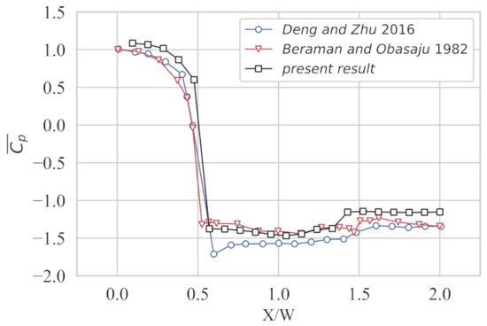
Figure 3.
Comparisons of mean pressure distribution between previous studies and present numerical simulations.
Table 2.
Comparisons of force coefficients between previous studies and present numerical simulations.
2.4. Simulation Cases
As shown in Figure 4, two types of simulation cases, stationary and rotating wind turbines, are considered. For the stationary wind turbines, their orientation related to the wind flow direction may have a significant effect on aerodynamic characteristics of the cylinder. Similarly, for the rotating wind turbines, it is anticipated that the rotation speed of the turbines is a key factor which affects the aerodynamic characteristics of the cylinder. In order to study the effects of these two factors, 4 different orientations of the stationary wind turbines and 9 different rotation speeds are studied, as shown in Table 3 and Table 4. The orientation of the stationary turbine is denoted by θ, which represents the angle of rotation of the wind turbines. Two wind turbines rotate inward relative to the square cylinder. Vt is the rotation speed of the wind turbines and fs is the vortex shedding frequency of the square cylinder calculated according to Strouhal number of 0.132 for the square cylinder provided by [22]. The rotation speed ranges from 0 to 4 times that of fs, and a rotation speed of 0 refers to a stationary case. In this study, the turbine rotates independently from the wind speed. According to [30], the rotation speed of the Savonius wind turbine is about 19.5 (r/s), which is closest to the rotation speed of R6. Thus, R6 is considered as an actual case. In order to conduct a comparative study on the influence of different rotational speeds on the aerodynamic characteristics of the square cylinder, we created 8 other working conditions.
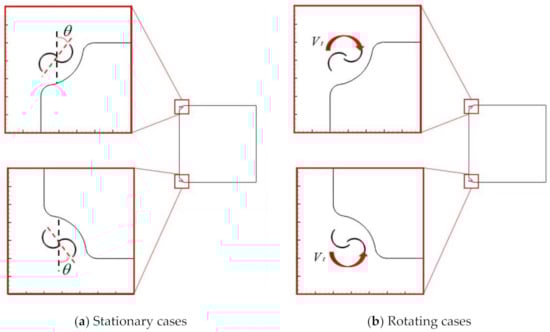
Figure 4.
Simulation cases: (a) Stationary cases; (b) Grid surrounding square cylinder.
Table 3.
Rotating test cases.
Table 4.
Stationary test cases.
3. Results and Discussions
3.1. Mean Pressure Coefficients
3.1.1. Stationary Wind Turbines at Cylinder Corners
Comparisons of mean pressure coefficients () around the cylinder surface among the four cases with stationary wind turbines at the cylinder corners and the plain cylinder are provided in Figure 5.
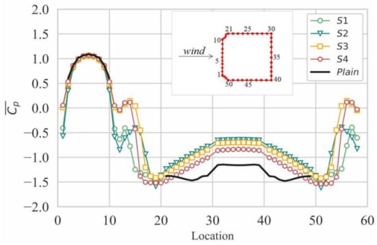
Figure 5.
Mean pressure coefficients around the cylinder for the four stationary cases and plain cylinder.
On the windward face, at the stagnation point is approximately 1.0 for all cases. gradually decreases from the stagnation point to two corners and on two side faces are symmetrically distributed as expected. Because of the flow separation, the value of on two side faces is negative. Compared with the cases with turbines at corners, on the side faces of the plain cylinder has the lowest value. It means that the existence of stationary wind turbines in the corners reduces the suction on the side faces. Furthermore, on the side faces has the largest value when is (S2), which means that the suction on the side faces of S2 is lower than the other cases.
On the leeward face, the suctions for cases with stationary wind turbines are significantly lower than that of the plain cylinder. Similar to the observations on the side face, the stationary wind turbines weaken the suction on the leeward face and it becomes more obvious when is , i.e., S2.
3.1.2. Rotating Wind Turbines at Cylinder Corners
Mean pressure coefficients () around the cylinder surfaces of nine rotating cases and the plain cylinder are compared in Figure 6. Figure 6a presents the cases when Vt/fs is less than 1 while Figure 6b shows the cases when Vt/fv is equal to or larger than 1.
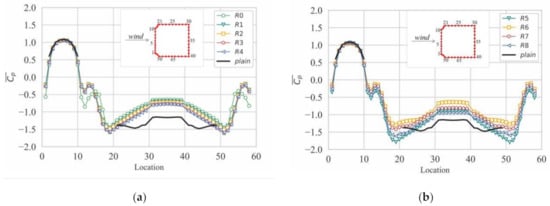
Figure 6.
Mean pressure coefficients around the cylinder for the nine rotating cases and the plain cylinder: (a) Vt/fs < 1; (b) Vt/fs ≥ 1.
On the two side faces, of the plain cylinder has the lowest value among the nine cases. Therefore, the existence of rotating wind turbines in the corner reduces the suction on the two side faces. As shown in Figure 6a, the suction on the two sides increases as the rotation speed increases when the rotation speed of wind turbines is less than fs. As shown in Figure 6b, the suction on the two sides has an obvious reduction when the wind turbine rotation speed increases from fs (R5) to 2fs (R6). Lastly, the suction will not be lower than R6 as the rotation speed further increases.
On the leeward face, the suction of cases with the rotating wind turbines is lower than the plain cylinder. Similar to the observations on the side faces, it is believed that the rotating wind turbine is able to weaken the suction on the leeward face. It is also noted that the suction on the leeward face has the lowest value, as shown in Figure 6b, when the rotating speed is 2fs (R6).
3.2. Force Coefficients and Vortex Shedding Characteristics
3.2.1. Stationary Wind Turbines at Cylinder Corners
, , and of four stationary cases and the plain cylinder are listed in Table 5. The percentage of the values relative to the plain cylinder is shown in Figure 7.
Table 5.
Force coefficient for four stationary cases and plain cylinder.
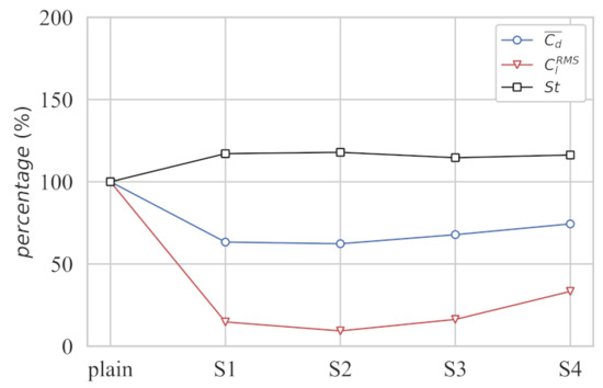
Figure 7.
Comparisons of RMS lift coefficients, mean drag coefficients, and Strouhal number for the four stationary cases and plain cylinder.
As shown in Table 5 and Figure 7, four cases with stationary wind turbines have lower than the plain cylinder since the suction on the two sides and leeward face is lower than the plain cylinder, as shown in Figure 5.
As shown in Figure 7, is reduced 37.7% compared to the plain cylinder when is 45° (S2), which is the most significant for all cases. The lowest suction on the leeward face shown in Figure 5 contributes to the lowest of S2. The variation in is similar to that of and the RMS lift coefficients has a 90.7% reduction when is 45° (S2). That is to say, the fluctuation of was suppressed effectively. There is still a drop of 66.7% of compared with the plain cylinder when is 135° (S4). Figure 8a,b presents the comparison of time history of Cl for S2 and S4. The red curve represents the time history of Cl of the plain cylinder and the black curves represent the time history of the typical cases. It can be found that the fluctuation of Cl for S2 has a greater inhibition than S4.
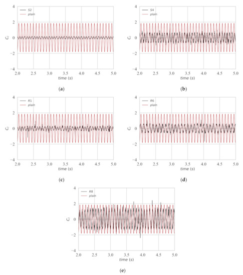
Figure 8.
Comparison of time history of Cl: (a) S2; (b) S4; (c) R1; (d) R6; (e) R8.
Figure 9 illustrates the power spectrum of the lift force for the four stationary cases and plain cylinder; the vortex shedding energy is represented by the peak value of the spectrum. The frequency corresponding to the maximum value of the power spectrum is the vortex shedding frequency, and then can be calculated by (W is the width of the cylinder and U is the wind speed). As shown in Figure 9, the spectrum of the lift coefficient of the plain cylinder fits well with that in [31]. Four stationary cases have a much larger Strouhal number, approximately 20% larger than that of the plain cylinder. The vortex shedding energy presented by the peak value of the spectrum of four stationary cases is evidently smaller than that of the plain cylinder. Even though the stationary wind turbines installed at two leading corners increase the frequency of vortex shedding of the square cylinder, they can effectively reduce the energy of vortex shedding. Furthermore, the vortex shedding energy of the cylinder with corner wind turbines exhibits the lowest value when is 45° (S2).
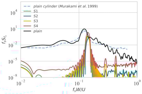
Figure 9.
Power spectra of lift forces for the four stationary cases and plain cylinder.
3.2.2. Rotating Wind Turbines at Cylinder Corners
, , and of the nine rotating cases and the plain cylinder are listed in Table 6. Ratios of these values to that for the plain cylinder are shown in Figure 10. All cases of the square cylinder with rotating corner wind turbines have lower mean drag coefficients () than the plain cylinder. Compared with the plain cylinder, when the rotation speed is 0.2fs (R1), of the cylinder with wind turbines dramatically decreases by about 34.2%, and then the drop rate gradually decreases as the rotating speed increases before reaching fs. When the rotation speed increases to 2fs (R6), the drop rate of again increases to 34.2%. Similarly, all cases of the square cylinder with rotating corner wind turbines have lower than the plain cylinder. As rotation speed increases, the variation in the drop rate of is similar to that of , but the reduction in is more significant than . Compared with the plain cylinder, of the cylinder with corner wind turbines dramatically decreases by about 86.0% as the wind turbine rotation speed is 0.2fs(R1) and the drop rate becomes 71.3% when the rotating speed increases to 2fs (R6). When the rotation speed is 4fs(R8), both and have the least reduction. It is worth noting that even though and have a significant reduction when the wind turbine has a rotating speed of 0.2fs and 2fs, it is still smaller than the reduction in the case with the stationary wind turbines (R0). Figure 8c–e present the comparison of time history of Cl of R1, R6, and R8. It can be found that the fluctuation of Cl of R1 is smallest, which corresponds to the largest drop rate of of R1. Figure 8d,e shows that the fluctuation of Cl of R6 is also effectively suppressed, but the effect of fluctuation inhibition of R8 is not obvious.
Table 6.
Force coefficient for the nine rotating cases and plain cylinder.
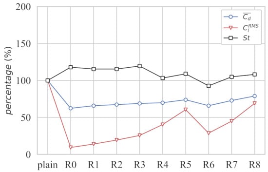
Figure 10.
Comparisons of RMS lift coefficients, mean drag coefficients, and Strouhal number for the nine rotating cases and the plain cylinder.
Figure 11 presents the power spectrum of the lift force for the nine rotating cases and plain cylinder. Figure 11a refers to the cases with Vt/fs less than 1 and Figure 11b shows the cases with Vt/fs equal to or larger than 1. For Strouhal number () shown in Figure 11, all of the rotating cases have larger Strouhal numbers than the plain cylinder, except for R6. The vortex shedding energy represented by the peak value of the spectrum of the nine rotating cases is evidently smaller than that of the plain cylinder. Moreover, the vortex shedding energy of the cylinder with corner wind turbines has the lowest value when the wind turbine rotation speed is 2fs (R6).
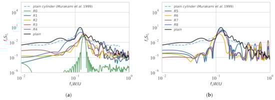
Figure 11.
Power spectra of lift forces for the nine rotating cases and plain cylinder: (a) Vt/fs < 1; (b) Vt/fs ≥ 1.
3.3. Flow Pattern around the Cylinders
The considerable effects of stationary and rotating wind turbines on the aerodynamic characteristics of a square cylinder are explained above. It can be found that there is a significant difference between aerodynamic characteristics of a plain square cylinder and a square cylinder with stationary or rotating wind turbines at the corners. To clarify the related mechanism, the flow patterns are discussed in this section.
3.3.1. Stationary Wind Turbines at Cylinder Corners
Time-averaged pressure coefficient distribution around the plain cylinder and the cylinder of the two stationary cases (S2 and S4) are shown in Figure 12a–c. As for the stationary cases, S2 has the best effect of drag reduction while S4 has the worst result, thus the flow pattern of these two cases is discussed herein. As for S2, the pressure distribution on the windward face is consistent with the plain cylinder, but the negative pressures coefficient of 0.68 on the leeward face is much smaller than 1.4 of the plain cylinder, which leads to a significant decrease in , as presented in Figure 7. The time-averaged pressure coefficient on the leeward face of S4 is about −0.84, leading to a 25.6% decrease in .
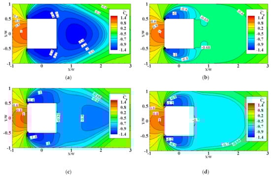
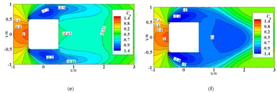
Figure 12.
Time-averaged pressure coefficient distribution: (a) plain cylinder; (b) S2; (c) S4; (d) R1; (e) R6; (f) R8.
Time-averaged streamlines around the plain cylinder and the cylinder of the two stationary cases (S2 and S4) are shown in Figure 13a–c. For the plain cylinder, two recirculation zones beside the side faces and a pair of recirculation zones which are symmetrically distributed in the near wake can be found. The color of the streamline represents the x component of the velocity (U). It can be found that the wind flow has an increasing speed effect at the corner. The length of the recirculation zones is defined as the length between the plain cylinder center and the saddle point of the time-averaged streamtraces along the centerline of the test models [15,32,33]. It has been reported that the drag coefficient is inversely proportional to the length of the recirculation zones in studies on drag reduction for square cylinders with cut-corners at the front edges [4] and the bluff body fitted with a splitter plate [34,35,36,37]. Less fluctuating lift coefficient can also be attributed to the elongated wake recirculation zone [29,38,39]. Apparently, the wake recirculation zone is dramatically elongated when is 45° (S2) compared with the plain cylinder and S4. Therefore, lower and for S2 shown in Table 5 can be inferred. By contrast, the elongation of the length of the recirculation zone in S4 is shorter than S2, leading to only a 25.6% decrease in compared with the plain cylinder, as presented.
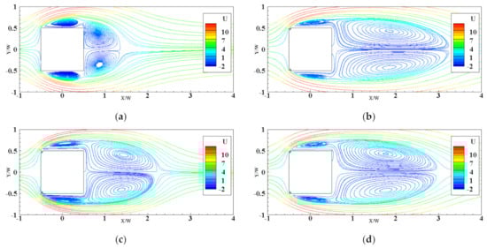
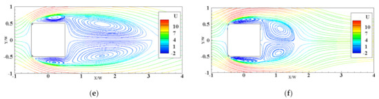
Figure 13.
Time-averaged streamlines around the cylinder: (a) plain cylinder; (b) S2; (c) S4; (d) R1; (e) R6; (f) R8.
The suction on the side faces and leeward face depends on the curvature of the separated shear layer, the suction increases as the curvature of the separated shear increases [29]. Figure 14a–c shows the normalized time-averaged vorticity distributions of the plain cylinder and S2 and S4. When is 45° (S2), the contour of normalized time-averaged vorticity distributions becomes thinner than that of the plain cylinder, which means the separated shear layer has smaller curvature, resulting in the lower suction that is shown in Figure 5. However, the contour of the normalized time-averaged vorticity distributions of the plain cylinder is stubbier, which means the curvature of the separated layer of the plain cylinder is larger. This may cause the increase in suction on the side faces and leeward faces of the plain cylinder, which may further lead to the increase of in the structure.
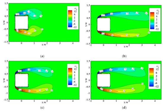
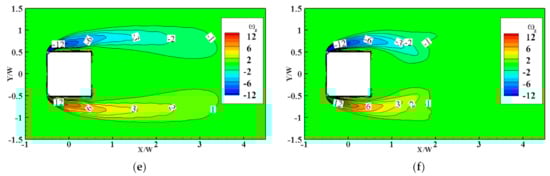
Figure 14.
Normalized time-averaged vorticity distributions: (a) plain cylinder; (b) S2; (c) S4; (d) R1; (e) R6; (f) R8.
Compared with the instantaneous spanwise vorticity distributions of the plain cylinder as shown in Figure 15a, the normalized instantaneous spanwise vorticity distributions in one period of S2 in Figure 15b indicate that the stationary wind turbines push the separated shear layer away and the vortices form farther downstream compared with the plain cylinder, which weakens its interaction with the side faces [38,40,41,42,43]. The weaker interaction causes a lower spectrum peak in the lift force spectrum in Figure 8 and lower , as shown in Figure 7. Overall, the stationary wind turbines installed in the corner can reduce the mean drag force and the fluctuation of lift remarkably.
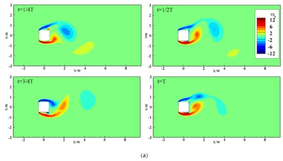
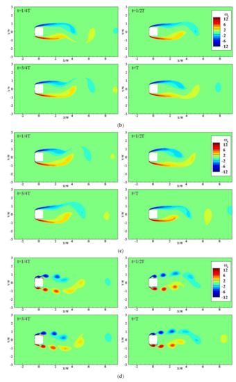
Figure 15.
Normalized instantaneous vorticity distributions during one period: (a) plain cylinder; (b) S2; (c) R1; (d) R6.
3.3.2. Rotating Wind Turbines at Cylinder Corner
Time-averaged pressure coefficient distributions of the three rotating cases are shown in Figure 12d–f. (R1 and R6 have excellent effects of drag reduction while R8 has the worst result). The pressure distributions on the windward face of R1 and R6 are consistent with the plain cylinder, but R1 and R6 have lower negative pressure coefficients (0.7 and 0.65) on the leeward face, leading to about a 35% decrease in drag coefficient, as presented in Table 6.
Time-averaged streamlines around the cylinder of the three rotating cases and the plain cylinder are shown in Figure 13d–f. Apparently, compared with the plain cylinder, the wake recirculation zones are dramatically elongated when the rotation speeds are 0.2fs(R1) and 2fs(R6). Thus, 86.0% and 71.3% decrease in of R1 and R6 can be observed. On the contrary, the wake recirculation zone of R8 is shorter than that of R6, which results in a worse effect on drag reduction.
Figure 14d–f shows the normalized time-averaged vorticity distributions of R1, R6, and R8. When the rotating speed is 2fs(R6), the contour of normalized time-averaged vorticity distributions becomes more elongated than the plain cylinder, and the separated shear layer has smaller curvature due to the lower suction, as shown in Figure 6. As for R1, the situation is similar. However, the curvature of the separated shear layer of R8 is distinctly larger, so the suction of R8 is greater than R1 and R6.
In Figure 15d, the symmetrical vortex shedding is observed in the normalized instantaneous vorticity distributions during one period of R6. The typical Karman-type vortex shedding is replaced by the symmetric shedding modes, which can lead to the large suppression of lift fluctuations shown in Figure 9. That is why the RMS lift coefficient () of R6 is significantly lower than that of the plain cylinder. As for R1, when the rotation speed is 0.2fs, the normalized instantaneous vorticity distribution during one period, shown in Figure 15c, is similar to S2, which means that R1 has a similar mechanism of drag reduction as S2.
4. Concluding Remarks
This is a preliminary study to investigate the aerodynamic characteristics of a square cylinder with Savonius wind turbines and to explain the reason why this kind of structure can suppress wind-induced vibrations. The results indicate that the turbine orientation and the turbine rotation speed are the key factors that affect aerodynamic characteristics of the square cylinder. The numerical simulation results show that presence of either the stationary or the rotating wind turbines has a significant effect on wind forces acting on the square cylinder. The stationary wind turbines and rotating wind turbines installed at the leading corners can reduce both and of the plain cylinder. For the stationary wind turbine cases, when the turbine orientation angle is 45°, the stationary wind turbines push the separated shear layer away and the vortices form farther away from the square cylinder compared with the plain cylinder, which weakens its interaction with the side faces, thus causing 37.7% and 90.7% reduction in the mean drag and fluctuating lift coefficients, respectively. For the rotating wind turbine cases, the mean drag and fluctuating lift coefficients are reduced by 34.2% and 86.0%, respectively, when the rotation speed is 0.2 times of vortex shedding frequency. When the rotation speed is twice the vortex shedding frequency, the typical Karman-type vortex shedding is replaced by the symmetric shedding modes, which leads to a large suppression of lift fluctuations (71.3%) and mean drag (34.2%).
This study investigated the effect of stationary or rotating Savonius wind turbines with two blades on the aerodynamic characteristics of a square cylinder. For the next stage, other Savonius wind turbines with more blades will be considered to investigate the effects of blades on the aerodynamic performance of a square cylinder.
Author Contributions
Conceptualization, G.H. and Y.X.; methodology, G.H., F.X. and D.Z.; software, Z.W.; validation, Z.W., G.H. and D.Z.; formal analysis, Z.W. and D.Z.; investigation, Z.W. and F.X.; resources, G.H. and Y.X.; data curation, Z.W. and B.K.; writing—original draft preparation, Z.W.; writing—review and editing, G.H., D.Z., B.K., F.X. and Y.X.; visualization, Z.W.; supervision, G.H. and Y.X.; project administration, G.H.; funding acquisition, G.H. and Y.X. All authors have read and agreed to the published version of the manuscript.
Funding
This study was supported by National Key R&D Program of China (2021YFC3100702), National Natural Science Foundation of China (52108451, 52078175), Shenzhen Science and Technology Innovation Commission (GXWD20201230155427003-20200823230021001, GXWD20201230155427003-20200823134428001), Shenzhen Key Laboratory Launching Project (ZDSYS20200810113601005), and Guangdong–Hong Kong–Macao Joint Laboratory for Data-Driven Fluid Mechanics and Engineering Applications (2020B1212030001).
Institutional Review Board Statement
Not applicable.
Informed Consent Statement
Not applicable.
Conflicts of Interest
The authors declare no conflict of interest.
References
- Carassale, L.; Freda, A.; Marre-Brunenghi, M. Experimental investigation on the aerodynamic behavior of square cylinders with rounded corners. J. Fluids Struct. 2014, 44, 195–204. [Google Scholar] [CrossRef]
- Tamura, T.; Miyagi, T. The effect of turbulence on aerodynamic forces on a square cylinder with various corner shapes. J. Wind. Eng. Ind. Aerodyn. 1999, 83, 135–145. [Google Scholar] [CrossRef]
- Tamura, T.; Miyagi, T.; Kitagishi, T. Numerical prediction of unsteady pressures on a square cylinder with various corner shapes. J. Wind. Eng. Ind. Aerodyn. 1998, 74, 531–542. [Google Scholar] [CrossRef]
- He, G.S.; Li, N.; Wang, J.J. Drag reduction of square cylinders with cut-corners at the front edges. Exp. Fluids 2014, 55, 1745. [Google Scholar] [CrossRef]
- Kurata, M.; Ueda, Y.; Kida, T.; Iguchi, M. Drag reduction due to cut-corners at the front-edge of a rectangular cylinder with the length-to-breadth ratio being less than or equal to unity. J. Fluids Eng. 2009, 131, 064501. [Google Scholar] [CrossRef]
- Tse, K.; Hitchcock, P.A.; Kwok, K.C.; Thepmongkorn, S.; Chan, C.M. Economic perspectives of aerodynamic treatments of square tall buildings. J. Wind. Eng. Ind. Aerodyn. 2009, 97, 455–467. [Google Scholar] [CrossRef]
- Kwok, K.; Wilhelm, P.A.; Wilkie, B.G. Effect of edge configuration on wind-induced response of tall buildings. Eng. Struct. 1988, 10, 135–140. [Google Scholar] [CrossRef]
- Kwok, K.C.; Bailey, P.A. Aerodynamic devices for tall buildings and structures. J. Eng. Mech. 1987, 113, 349–365. [Google Scholar] [CrossRef]
- Bearman, P.W.; Trueman, D.M. An investigation of the flow around rectangular cylinders. Aeronaut. Q. 1972, 23, 229–237. [Google Scholar] [CrossRef]
- Modi, V.J.; Deshpande, V.S. Fluid dynamics of a cubic structure as affected by momentum injection and height. J. Wind. Eng. Ind. Aerodyn. 2001, 89, 445–470. [Google Scholar] [CrossRef]
- Munshi, S.R.; Modi, V.J.; Yokomizo, T. Aerodynamics and dynamics of rectangular prisms with momentum injection. J. Fluids Struct. 1997, 11, 873–892. [Google Scholar] [CrossRef]
- Hu, G.; Tse, K.T.; Wei, M.; Naseer, R.; Abdelkefi, A.; Kwok, K. Experimental investigation on the efficiency of circular cylinder-based wind energy harvester with different rod-shaped attachments. Appl. Energy 2018, 226, 682–689. [Google Scholar] [CrossRef]
- Li, Q.S.; Chen, F.B.; Li, Y.G.; Lee, Y.Y. Implementing wind turbines in a tall building for power generation: A study of wind loads and wind speed amplifications. J. Wind. Eng. Ind. Aerodyn. 2013, 116, 70–82. [Google Scholar] [CrossRef]
- Jafari, S.; Kwok, K.C.; Hassanli, S. Integration of wind turbines in tall buildings for wind power generation. In Proceedings of the 8th International Colloquium on Bluff Body Aerodynamics and Applications, Boston, MA, USA, 7–11 June 2016. [Google Scholar]
- Cochran, B.C.; Damiani, R.R. Harvesting wind power from tall buildings. In Wind Power; CPP, Inc.: Mountain View, CA, USA, 2008. [Google Scholar]
- Li, T.; Qin, D.; Zhang, J. Effect of RANS turbulence model on aerodynamic behavior of trains in crosswind. Chin. J. Mech. Eng. 2019, 32, 85. [Google Scholar] [CrossRef] [Green Version]
- Lu, Y.; Yang, M.; Qian, B. The influence of reduced cross-section on pressure transients from high-speed trains intersecting in a tunnel. J. Wind. Eng. Ind. Aerodyn. 2020, 201, 104–161. [Google Scholar] [CrossRef]
- Deng, E.; Yang, W.; He, X.; Zhu, Z.; Wang, H.; Wang, Y. Aerodynamic response of high-speed trains under crosswind in a bridge-tunnel section with or without a wind barrier. J. Wind. Eng. Ind. Aerodyn. 2021, 210, 104–502. [Google Scholar] [CrossRef]
- Wang, T.; Wu, F.; Yang, M.; Ji, P.; Qian, B. Reduction of pressure transients of high-speed train passing through a tunnel by cross-section increase. J. Wind. Eng. Ind. Aerodyn. 2018, 183, 235–242. [Google Scholar] [CrossRef]
- Rodi, W.; Ferziger, J.H.; Breuer, M.; Pourquie, M. Status of large eddy simulation: Results of a workshop. Trans.-Am. Soc. Mech. Eng. J. Fluids Eng. 1997, 119, 248–262. [Google Scholar] [CrossRef]
- Voke, P.R. Flow past a square cylinder: Test case LES2. In Direct and Large-Eddy Simulation II; Kleiser, L., Ed.; Springer: Dordrecht, The Netherlands, 1997; Volume 5, pp. 355–373. [Google Scholar]
- Deng, Y.; Zhu, Z. Numerical simulation of two dimensional flow around square column at full wind Angle. J. Railw. Sci. Eng. 2016, 13, 1796–1802. [Google Scholar]
- Bearman, P.W.; Obasaju, E.D. An experimental study of pressure fluctuations on fixed and oscillating square-section cylinders. J. Fluid Mech. 1982, 119, 297–321. [Google Scholar] [CrossRef]
- Lee, B.E. The effect of turbulence on the surface pressure field of a square prism. J. Fluid Mech. 1975, 69, 263–282. [Google Scholar] [CrossRef]
- Wang, Q.; Jiang, Q.; Hu, G.; Chen, X.; Li, C.; Xiao, Y. Aerodynamic characteristics of a square cylinder with corner fins. Adv. Bridge Eng. 2021, 2, 20. [Google Scholar] [CrossRef]
- Lyn, D.A.; Einav, S.; Rodi, W.; Park, J.H. A laser-Doppler velocimetry study of ensemble-averaged characteristics of the turbulent near wake of a square cylinder. J. Fluid Mech. 1995, 304, 285–319. [Google Scholar] [CrossRef]
- Lyn, D.A.; Rodi, W. The flapping shear layer formed by flow separation from the forward corner of a square cylinder. J. Fluid Mech. 1994, 267, 353–376. [Google Scholar] [CrossRef]
- Hangan, H.M. Wake Aerodynamics for 2D Bluff Bodies. Ph.D. Thesis, The University of Western Ontario, London, ON, Cnada, 1997. [Google Scholar]
- Xu, J. Effects of Vertical Clearance on Aerodynamic Characteristics of Long-Span Bridge Girders; Hunan University: Changsha, China, 2014. [Google Scholar]
- Wenehenubun, F.; Saputra, A.; Sutanto, H. An experimental study on the performance of Savonius wind turbines related with the number of blades. Energy Procedia 2015, 68, 297–304. [Google Scholar] [CrossRef] [Green Version]
- Murakami, S.; Iizuka, S.; Ooka, R. CFD analysis of turbulent flow past square cylinder using dynamic LES. J. Fluids Struct. 1999, 13, 1097–1112. [Google Scholar] [CrossRef]
- Gao, D.; Chen, G.; Chen, W.; Huang, Y.; Li, H. Active control of circular cylinder flow with windward suction and leeward blowing. Exp. Fluids 2019, 2, 60. [Google Scholar] [CrossRef]
- Konstantinidis, E.; Balabani, S.; Yianneskis, M. The effect of flow perturbations on the near wake characteristics of a circular cylinder. J. Fluids Struct. 2003, 18, 367–386. [Google Scholar] [CrossRef]
- Gao, D.; Chen, G.; Huang, Y.; Chen, W.; Li, H. Flow characteristics of a fixed circular cylinder with an upstream splitter plate: On the plate-length sensitivity. Exp. Therm. Fluid Sci. 2020, 117, 110135. [Google Scholar] [CrossRef]
- Gao, D.; Huang, Y.; Chen, W.; Chen, G.; Li, H. Control of circular cylinder flow via bilateral splitter plates. Phys. Fluids 2019, 31, 057105. [Google Scholar] [CrossRef]
- Bearman, P.W. Investigation of the flow behind a two-dimensional model with a blunt trailing edge and fitted with splitter plates. J. Fluid Mech. 1965, 21, 241–255. [Google Scholar] [CrossRef]
- Chen, W.; Xin, D.; Xu, F.; Li, H.; Ou, J.; Hu, H. Suppression of vortex-induced vibration of a circular cylinder using suction-based flow control. J. Fluids Struct. 2013, 42, 25–39. [Google Scholar] [CrossRef]
- Gao, D.; Meng, H.; Huang, Y.; Chen, G.; Chen, W. Active flow control of the dynamic wake behind a square cylinder using combined jets at the front and rear stagnation points. Phys. Fluids 2021, 33, 047–101. [Google Scholar] [CrossRef]
- Lam, K.; Lin, Y.F. Large eddy simulation of flow around wavy cylinders at a subcritical Reynolds number. Int. J. Heat Fluid Flow 2008, 29, 1071–1088. [Google Scholar] [CrossRef]
- Gao, D.; Chen, W.; Li, H.; Hu, H. Flow around a circular cylinder with slit. Exp. Therm. Fluid Sci. 2017, 82, 287–301. [Google Scholar] [CrossRef]
- Chen, W.; Gao, D.; Yuan, W.; Li, H.; Hu, H. Passive jet control of flow around a circular cylinder. Exp. Fluids 2015, 11, 56. [Google Scholar] [CrossRef]
- Gao, D.; Chen, W.; Chen, G.; Li, H. Effects of steady wake-jets on subcritical cylinder flow. Exp. Therm. Fluid Sci. 2019, 102, 575–588. [Google Scholar] [CrossRef]
- Gao, D.; Deng, Z.; Yang, W.; Chen, W. Review of the excitation mechanism and aerodynamic flow control of vortex-induced vibration of the main girder for long-span bridges: A vortex-dynamics approach. J. Fluids Struct. 2021, 105, 103348. [Google Scholar] [CrossRef]
Publisher’s Note: MDPI stays neutral with regard to jurisdictional claims in published maps and institutional affiliations. |
© 2022 by the authors. Licensee MDPI, Basel, Switzerland. This article is an open access article distributed under the terms and conditions of the Creative Commons Attribution (CC BY) license (https://creativecommons.org/licenses/by/4.0/).