Abstract
Biomedical implantable antennas play a vital role in medical telemetry applications. These types of biomedical implantable devices are very helpful in improving and monitoring patients’ living situations on a daily basis. In the present paper, a miniaturized footprint, thin-profile bear-shaped in-body antenna operational at 915 MHz in the industrial, scientific, and medical (ISM) band is proposed. The design is a straightforward bear-shaped truncated patch excited by a 50-Ω coaxial probe. The radiator is made up of two circular slots and one rectangular slot at the feet of the patch, and the ground plane is sotted to achieve a broadsided directional radiation pattern, imprinted on a Duroid RT5880 roger substrate with a typical 0.254-mm thickness ( = 2.2, tan = 0.0009). The stated antenna has a complete size of 7 mm × 7 mm × 0.254 mm and, in terms of guided wavelength, of 0.027 × 0.027 × 0.0011. When operating inside skin tissues, the antenna covers a measured bandwidth from 0.86 GHz to 1.08 GHz (220 MHz). The simulations and experimental outcomes of the stated design are in proper contract. The obtained results show that the calculated specific absorption rate (SAR) values inside skin of over 1 g of mass tissue is 8.22 W/kg. The stated SAR values are lower than the limitations of the federal communications commission (FCC). Thus, the proposed miniaturized antenna is an ultimate applicant for in-body communications.
1. Introduction
Biomedical gadgets are very helpful in different therapies and medical diagnoses. Due to this reason, they have attracted the focus of researchers in the past few years. They are helpful in improving and monitoring patients’ living situations daily. Implantable devices need to be connected to an external unit for data transmission. This is commonly done using a telemetry system, which has numerous benefits, including high data rate transmission over long-distance communication [1,2]. The antenna model proposed in the reference paper [3] is perfectly in line with the design criteria of implantable medical devices (IMDs). Figure 1 shows a schematic representation of the IMDs. The implantable antenna should be miniaturized, flexible, and have very low SAR values to be used for human care [4]. Throughout the model phase, the design ought to be companionable with and adaptive to the individual body. Human phantoms can be smashed by the antenna operation at the working frequency. Furthermore, the antenna should have a wide bandwidth to cover the required frequency range despite the impact of surrounding human tissue [5]. The many-layers structure of the human body causes the antenna’s radiation characteristics to shift frequency. The human body is made up of skin, fat, blood, and bones. All these different tissues have distinct dielectric characteristics. Thus, creating a biocompatible antenna that may be used in human body applications is difficult [6]. In Ref. [7], the authors presented the compact X-shaped slotted patch antenna of a size of 7 × 7 mm2, but the bandwidth achieved from the antennas was 21.85%, which was less than our proposed design in this paper, and the shape of the design was not as novel compared to our proposed design. Since it is not easy to achieve high bandwidth with compact size, our proposed design therefore has attained the wide bandwidth of 25.13%.
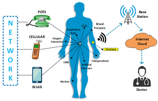
Figure 1.
Graphical representation of the in-body medical devices [7].
In the mid-radio range (402–405 MHz) [7,8,9,10] and the ISM band (2.4–2.48 GHz) [11,12,13,14,15,16], several implanted antennas have been stated for this wireless application. Ref. [8] presented another tiny wideband antenna that works in the MICS band for application in biomedical implants (403 MHz). In Ref. [8], the substrate used was Roger 6010, a flexible material with a thickness of 1.27 mm. The SAR values were found to be 284.5 W/kg over 1 g, which was higher than our suggested design. Ref. [10] presented another implantable ISM band biomedical antenna built on a Polyamide substrate. The antenna had a peak gain of −16.8 dBi and a working latency of 1.22%. The antenna’s overall surface area was 25 × 20 mm2. The achieved gain and operating bandwidth for the chosen frequency were reported as −34.9 dBi and 14.9%, respectively. Ref. [17] presented a tiny circularly polarized implanted antenna for medical applications with excellent impedance matching. The radiating patch had a shape like a circle, and the ground plane included an X-shaped slit. Rogers 3010 was used as the substrate, with a 0.634-mm thickness. The antenna profile was thick due to the dual layers of the substrate. However, the antenna was less suitable for human body applications, due to a high value of SAR of almost 649 W/kg, which was much higher than the IEEE/IEC 6270-1 set limit over 1 g of bulk tissue. Ref. [18] described an alternative in-body antenna to transfer the power wirelessly, operating at 915 MHz.
The antenna was 11 × 11 × 1.27 mm3 in size, printed on a Roger 3010 substrate with a 3.8% impedance bandwidth and a realized gain of roughly −29 dBi. However, no SAR values were determined, and the antenna’s size remained enormous with a restricted bandwidth. Ref. [19] described an ISM band antenna for biomedical purposes. The antenna measured 15 × 15 × 1.27 mm3, was fabricated on a substrate called Roger 3010, and operated at 915 MHz, with a 10.6% operating bandwidth.
The antenna was analyzed within the skin, and the values of the SAR were determined to be 517 W/kg, which was far higher than the figure proposed in this research. Other research [20] investigated a new broadband in-body antenna for biomedical uses at 915 MHz. The antenna’s total dimensions were 3.14 × 22.09 × 1.27 mm3, and the substrate material was Roger 3010, which had a thickness of 1.27 mm. At 915 MHz, the impedance bandwidth was 12.2%, and the realized gain was −32.8 dBi, and 778 W/kg was the SAR value. However, as compared to the suggested antenna in this study, this antenna had a larger dimension and a higher SAR value.
An annular ring-shaped CP antenna with an axial ratio bandwidth of 19.1% was published in [21] for biomedical applications. This circular antenna also had two layered flexible substrates dubbed Roger 3010, each with a height of 0.635 mm. The antenna functioned in the ISM band at 2.45 GHz, with an operational bandwidth of 8%. The SAR values for this antenna were estimated at 508 W/kg, which was greater than the standard limit. The antenna had a max gain of −17.5 dB. The antenna was bigger than our suggested flexible implantable antenna, hence the bending analysis was not explored.
A CPW-fed split-ring-resonator (SRR) = based implantable antenna for medical telemetry applications was shown in another work [22,23]. The antenna’s overall area was claimed to be 2422 mm2, and the flexible substrate was Polyimide with a thickness of 0.07 mm. The antenna was designed to be low-profile and suitable for in-vitro testing. In comparison to our projected antenna, the antenna was still somewhat enormous. At 2.45 GHz, the antenna’s realized gain and total operating bandwidth were stated to be −19.7 dB and 24.4%, respectively.
This paper presents a high bandwidth with a small implantable antenna with a size of 7 × 7 × 0.254 mm3 (0.027 × 0.027 × 0.0011) for medical applications, operating at the 915 MHz ISM band. The Rogers RT5880 substrate ( = 2.2, tan = 0.0009) is used in the design. At 915 MHz the 2D pattern of the design is broadsided directional both in E- and H-planes. Since the suggested design has a slotted ground plane, it has the potential to generate a broader bandwidth and lower antenna back-radiation into human skin tissues of a 25-mm2 surface area. Due to the wideband designed structure, the stated antenna covers a wide spectrum at 915 MHz, with a very good peak gain value. Under the influence of the physical body, the created antenna’s radiation efficiency and performance improves, while SAR values fall dramatically. This paper is divided into four sections. The first section introduces the applications and the literature of the previous work. It includes information on the planned research’s history, the problem statement, aims, and importance. The suggested antenna’s design analysis is covered in Section 2. The results and discussion are highlighted in Section 3, and the conclusion is described in Section 4.
2. Stated Antenna Design Analysis
This section presents a small-size wideband bear-shaped design with circular and rectangular slots inside the radiator and the slots inside the ground plane, fed through a coaxial probe of 50 Ω. As demonstrated in Figure 2, the provided antenna has discrete layers, including a resonator, a ground plane, and a substrate Roger RT5880 (= 2.2 and tan = 0.0009), with a 0.254-mm thickness. The antenna has an overall volume of 7 × 7 × 0.254 mm3 (0.027 × 0.027 × 0.0011). The ANSYS high frequency selective simulator (HFSS) software was used to simulate the proposed antenna. The antenna’s return loss at the operational frequency of 915 MHz was determined to be −20 dB. The working bandwidth is 230 MHz. Table 1 summarizes the antenna’s optimized parameters.
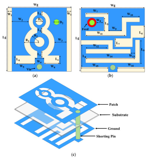
Figure 2.
Stated design structure; (a) front view, (b) back view, and (c) 3D view.

Table 1.
List of the parameters of the stated design.
2.1. Stated Antenna Design Procedure
The suggested antenna was designed in four steps, as illustrated in Figure 3. Different square parasitic patches in the patch and inside the ground plane of the antenna were designed to enhance the performance of the stated antenna. The performance of the stated implantable antenna is enhanced stepwise, as shown in the figure below. At a low frequency band, the relative permittivity value of the substrate does not change, while it increases with increased frequency. Hence, at intermediate frequencies, the rate of the relative permittivity raises. Equation (1) gives a dielectric constant at the initial stage [6]:
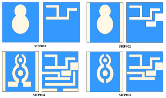
Figure 3.
Designing steps of the stated implantable antenna.
The height-to-width ratio equation helps in determining the dimensions of the antenna system. To account for fringing effects, the change in length, width, and height of the antennas’ substrate is selected using Equation (2) [9]:
where ‘’ stands for relative permittivity of the substrate, ‘h’ stands for the substrate height, ‘L’ stands for the change in patch length, and ‘W’ stands for patch width. The square-shaped patch antenna’s radiating and ground sections are separated into four segments, each with their own set of results. The patch was made of parasitic elements of various sizes.
In the first step, two circular slots inside the patch and a horizontal ‘4’-shaped slot is introduced inside the ground-plane. The return loss value was found to be more than −20 dB at the frequency of 420 MHz (see Figure 4). In the second step, the frequency is shifted from 420 MHz to 780 MHz (360 MHz shift) by creating two square-shaped slots inside the ground plane. In the third step, the frequency of the antenna is again shifted from 780 MHz to 1.15 GHz (370 MHz shift) after again creating a horizontal ‘4’ shaped slot inside the ground plane and creating circular rings in the patch of the second step. As 1.15 GHz is not our required band, to shift the band from 1.15 GHz to 915 MHz (a 235-MHz shift), the feet of the bear-shaped radiator is slotted with rectangular boxes, and rectangular and L-slots are introduced in the ground. Due to this, the antenna’s performance is improved, and the desired ISM (915 MHz) band is attained in the fourth step. The rectangular cuts on the patch and the ground are made using various rectangular cuts; the main goal of these cuts is to make the antenna smaller and lighter. The feed is located on the patch’s bottom right side. A shorting pin (via) is utilized to keep the stated antenna’s dimensions small. As a result, a shorting pin (via) of a radius of 0.5 mm is inserted, starting from the ground and ending in the patch. Figure 4 shows a comparison of the S11 of the suggested design steps. The design system of the bear-shaped patch implantable antenna is shown in Figure 5, and Figure 6 depicts the surface current distribution of the stated antenna. From the figures, it can clearly be seen that most of the current flows through the outer surface of the patch, while some amount of current flows around the ground near the shorting pin. The surface current indicates that a portion of the antenna is more resonant.
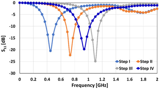
Figure 4.
S11 comparison of the corresponding antenna designing steps.
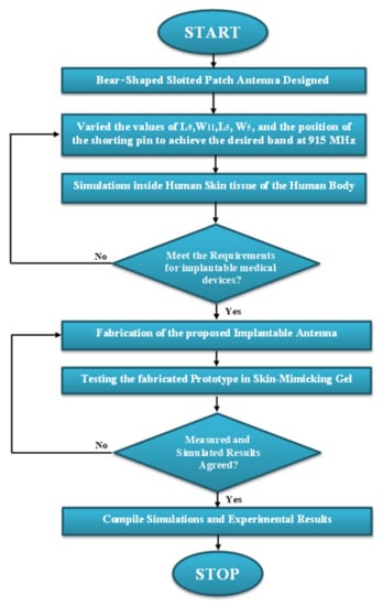
Figure 5.
Basic design process of the Beas-shaped patch implantable antenna.
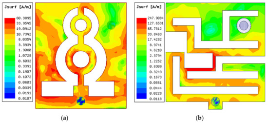
Figure 6.
Current distribution at 915 MHz throughout the (a) patch and (b) ground.
2.2. Parametric Optimization of the Stated Design
The parametric optimization and analysis of the proposed antenna and selection of the best parameters are important steps that will be discussed in this sub-section. Parametric optimization has proven the suitability of the selected parameters for the stated implantable antenna design. At 915 MHz, the reflection coefficient can be changed by adjusting the values of critical parameters, such as the length of the L-slot in the ground ‘L9’, the width of the upper horizontal ‘4’-shaped slot ‘W11’, the length of the slot in the ground near the probe ‘L5’, the width of the horizontal slot in the patch ‘W5’, and the position of the via.
Figure 7a shows how the frequency band is moved from 1.6 to 0.915 GHz by changing the value of ‘L9’ from 3.5 to 3 mm (685 MHz).
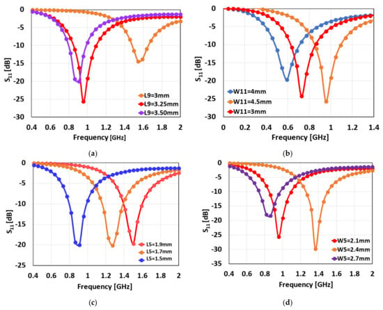
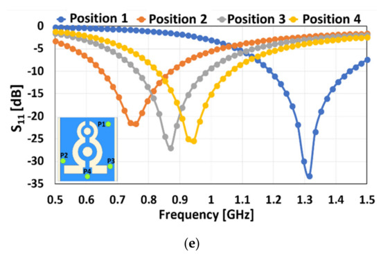
Figure 7.
Parametric optimization of the design; (a) change in ‘L9’, (b) change in ‘W11’, (c) change in ‘L5’, (d) deviation in ‘W5’, and (e) shifting the location of the via.
When the ‘W11’ value is modified from 3 mm to 4.5 mm, the frequency spectrum shifts from 0.6 to 0.915 GHz (500 MHz), as illustrated in Figure 7b.
Figure 7c shows that by increasing the value of the ‘L5’ from 1.5 mm to 1.9 mm the band range changes from 1.5 to 0.915 GHz (585 MHz).
When the value of ‘L6’ is altered from 2.1 mm to 2.7 mm, the frequency moves from 1.38 to 0.9 GHz (480 MHz), as illustrated in Figure 7d.
The frequency band is pushed higher than the targeted frequency band by adjusting the location of the via. The frequency band is 1.3 GHz when the through is positioned at position 1, 0.75 GHz at position 2, and 0.88 GHz at position 3. Finally, by moving the via from position 3 to position 4, as illustrated in Figure 7, the desired frequency band of 0.915 GHz is attained (e).
As illustrated in Figure 7, the position of the via not only influences the antenna’s impedance matching, but it also plays a key role in tuning the target frequency. Hence, it is seen that parametric optimization plays an imperative role in the impedance matching, tuning, and accomplishment of the desired frequency.
3. Results and Discussion
The proposed design is modelled inside skin tissue and measured inside skin-mimicking-gel tissue to confirm the simulated results. While calculating the SAR, the existence of human body phantoms must be considered in designing an antenna for biotelemetry applications with high precision. Therefore, the antenna performance near a human phantom, as well as the SAR values at 915 MHz, were assessed for this purpose. As shown in Figure 8a, the phantom box has an area of 25 × 25 mm2. The simulation was performed using the HFSS software. In an ideal situation, implantable antennas should reduce the otherwise significant coupling effects caused by human body tissues. The antenna was implanted 5 mm deep within the skin tissue of the human body during testing, as depicted in Figure 8. To evaluate these effects, the proposed antenna was placed within 25 mm × 25 mm of the skin layer. The antenna is in the phantom’s center. A uniform skin phantom with sizes of 25 × 25 × 25 mm3 was used to simulate and analyze the planned antenna. At 915 MHz, the properties used of the skin phantom were tan δ = 0.872, = 1.6 S/m, and = 41.33.
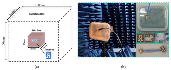
Figure 8.
Antenna inside skin-mimicking-gel; (a) perception view and (b) the experimental setup to measure the radiation pattern and S11 inside the skin.
Figure 9 depicts the difference between the simulations and experimental results for the reflection coefficients of the antenna inside the skin. The suggested biomedical antenna operated from 870 MHz to 1.1 GHz (230 MHz) at 915 MHz, according to the calculated S11 under the skin, whereas the constructed antenna inside the skin-mimicking-gel had a bandwidth spanning from 860 MHz to 1.08 GHz (220 MHz). This shows that the simulated and measured values were quite similar.
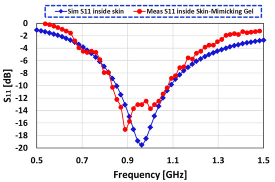
Figure 9.
Contrast between the simulation and measurement results of S11 inside skin-gel.
The E and H planes of the simulated and measured values of the radiation pattern inside the skin-gel are shown in Figure 10. The operation of the antenna within the skin was defined by the 2D radiation pattern. At 915 MHz, the antenna inside the skin showed a broadsided directional pattern in both planes. The simulated realized gain within skin at 915 MHz was −22 dBi. However, the measured results revealeed a realized gain value of −28 dB. Figure 11 depicts the simulated and observed radiation efficiency and gain graph. The antenna had a simulated radiation efficiency of 2.2%, whereas the measured radiation efficiency within the skin was 2.1%.
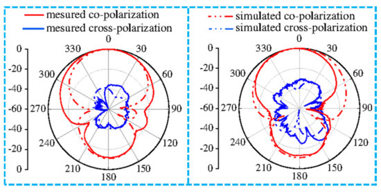
Figure 10.
Simulation and measurement far field results at 915 MHz inside the skin-gel.
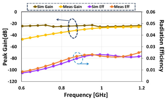
Figure 11.
Simulated and measured gain and radiation efficiency inside skin.
Specific Absorption Rate (SAR)
The electromagnetic waves may pose a health risk to humans, and these hazards are determined by means of Sthe AR. The following is the relation between the input power and SAR [7,8,9,10]:
The electric power intensity is proportional to the signal power, as given in the Equation (4) [10], where ‘σ’ and ‘ρ’ are electric conductivity (S/m) and mass density (kg/m3), respectively, and E is the electric field intensity (V/m).
The SAR is calculated according to the IEEE/IEC 6270-1 standard, averaged across 1 g of mass tissue, with the input power ‘Pin’ held stable at 0.5 W. As shown in Figure 12, the SAR values inside the skin were 8.22 W/kg at 915 MHz.
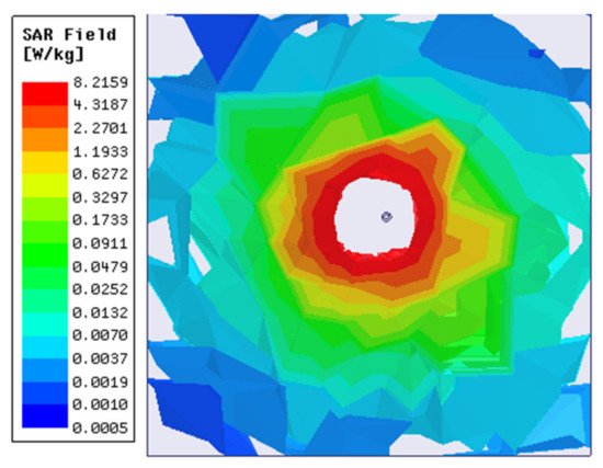
Figure 12.
At 915 MHz, SAR distribution of the specified antenna inside the skin tissue over 1 g.
The proposed design is compared to the state-of the art in the literature in Table 2. From the table, the proposed design is smaller in size and achieved a much wider bandwidth and much lower value of the specific absorption rate (SAR) than the other reported designs in the literature.
Table 2.
A comparison of the proposed antenna’s performance to that of recent work.
4. Conclusions
This work presented a low-profile slotted patch antenna, with a compact size, for use in biomedical implants. The proposed antenna resonates at 915 MHz in the ISM band. The antenna is made of Rogers RT/Duroid 5880 material ( = 2.2, tan δ = 0.0009) and has the overall dimensions 7 mm × 7 mm × 0.254 mm. At 915 MHz, the antenna’s observed gain is −28 dB, while the measured bandwidth is 220 MHz inside the skin-mimicking-gel material. The SAR values inside skin tissue were 8.22 W/kg. The biocompatibility and safety considerations in medical application design were also investigated. The stated antenna is compact enough to be implanted in biomedical applications. Considering the overall performance, the stated design is an ideal candidate for the targeted medical application.
Author Contributions
Conceptualization, S.A., B.M., K.N.P., S.H., A.G., M.A. and M.D.; methodology, S.A., K.N.P., M.L., A.J.A.A.-G., A.G., M.A. and M.D.; software, S.A. and B.M.; validation, S.A., B.M., K.N.P., S.H., M.L., A.J.A.A.-G., A.G., M.A. and M.D.; formal analysis, S.A., B.M., S.H., M.L., M.A. and M.D.; investigation, S.A., S.H., A.J.A.A.-G., A.G., M.A. and M.D.; resources, S.A., B.M., K.N.P., S.H., M.L., A.J.A.A.-G. and A.G.; data curation, S.A., B.M., K.N.P., S.H., M.L., A.J.A.A.-G. and A.G.; writing—original draft preparation, S.A.; writing—review and editing, S.A., B.M., K.N.P., S.H., M.L., A.J.A.A.-G., A.G., M.A. and M.D.; visualization, S.A., B.M., A.G., M.A. and M.D.; supervision, A.G., M.A. and M.D.; project administration, S.A., A.G., M.A. and M.D.; funding acquisition, M.A. and M.D. All authors have read and agreed to the published version of the manuscript.
Funding
This project received funding from Universidad Carlos III de Madrid and the European Union’s Horizon 2020 research and innovation program, under the Marie Sklodowska-Curie Grant 801538. It also received partial funding from the Researchers Supporting Project number (RSP-2021/399), King Saud University, Riyadh, Saudi Arabia.
Data Availability Statement
All data have been included within the manuscript.
Acknowledgments
The authors appreciate financial support from Universidad Carlos III de Madrid and the European Union’s Horizon 2020 research and innovation program under the Marie Sklodowska Curie Grant 801538. In addition, the partial support from the Researchers Supporting Project number (RSP-2021/399), King Saud University, Riyadh, Saudi Arabia, is acknowledged.
Conflicts of Interest
The authors declare that they have no conflict of interest.
References
- Yousaf, M.; Ben Mabrouk, I.; Zada, M.; Akram, A.; Amin, Y.; Nedil, M.; Yoo, H. An Ultra-Miniaturized Antenna with Ultra-Wide Bandwidth Characteristics for Medical Implant Systems. IEEE Access 2021, 9, 40086–40097. [Google Scholar] [CrossRef]
- Ghaffar, A.; Awan, W.A.; Hussain, N.; Ahmad, S.; Li, A.X.J. A compact dual-band flexible antenna for applications at 900 and 2450 MHZ. Prog. Electromagn. Res. Lett. 2021, 99, 83–91. [Google Scholar] [CrossRef]
- Nguyen, D.; Seo, C. An Ultra-Miniaturized Antenna Using Loading Circuit Method for Medical Implant Applications. IEEE Access 2021, 9, 111890–111898. [Google Scholar] [CrossRef]
- Yousaf, M.; Ben Mabrouk, I.; Faisal, F.; Zada, M.; Bashir, Z.; Akram, A.; Nedil, M.; Yoo, H. Compacted Conformal Implantable Antenna with Multitasking Capabilities for Ingestible Capsule Endoscope. IEEE Access 2020, 8, 157617–157627. [Google Scholar] [CrossRef]
- Singh, M.S.; Ghosh, J.; Ghosh, S.; Sarkhel, A. Miniaturized Dual-Antenna System for Implantable Biotelemetry Application. IEEE Antennas Wirel. Propag. Lett. 2021, 20, 1394–1398. [Google Scholar] [CrossRef]
- Xia, Z.; Li, H.; Lee, Z.; Xiao, S.; Shao, W.; Ding, X.; Yang, X. A Wideband Circularly Polarized Implantable Patch Antenna for ISM Band Biomedical Applications. IEEE Trans. Antennas Propag. 2019, 68, 2399–2404. [Google Scholar] [CrossRef]
- Ahmad, S. X-Shaped Slotted Patch Biomedical Implantable Antenna for Wireless Communication Networks. Wirel. Commun. Mob. Comput. 2022, 2022, 11. [Google Scholar] [CrossRef]
- Xu, L.-J.; Bo, Y.; Lu, W.-J.; Zhu, L.; Guo, C.-F. Circularly Polarized Annular Ring Antenna with Wide Axial-Ratio Bandwidth for Biomedical Applications. IEEE Access 2019, 7, 59999–60009. [Google Scholar] [CrossRef]
- Li, R.; Li, B.; Du, G.; Sun, X.; Sun, H. A Compact Broadband Antenna with Dual-Resonance for Implantable Devices. Micromachines 2019, 10, 59. [Google Scholar] [CrossRef] [Green Version]
- Naik, K.K.; Teja, S.C.S.; Sailaja, B.V.S.; Sri, P.A.V. Design of flexible parasitic element patch antenna for biomedical application. Prog. Electromagn. Res. M 2020, 94, 143–153. [Google Scholar] [CrossRef]
- Sulaiman, N.H.; Samsuri, N.A.; Rahim, M.K.A.; Seman, F.C.; Inam, M. Compact Meander Line Telemetry Antenna for Implantable Pacemaker Applications. Indones. J. Electr. Eng. Comput. Sci. 2018, 10, 883–889. [Google Scholar] [CrossRef]
- Loktongbam, P.; Pal, D.; Koley, C. Design of an implantable antenna for biotelemetry applications. Microsyst. Technol. 2020, 26, 2217–2226. [Google Scholar] [CrossRef]
- Ganeshwaran, N.; Jeyaprakash, J.K.; Alsath, M.G.N.; Sathyanarayanan, V. Design of a Dual-Band Circular Implantable Antenna for Biomedical Applications. IEEE Antennas Wirel. Propag. Lett. 2019, 19, 119–123. [Google Scholar] [CrossRef]
- Lei, W.; Chu, H.; Guo, Y. Design of a Circularly Polarized Ground Radiation Antenna for Biomedical Applications. IEEE Trans. Antennas Propag. 2016, 64, 2535–2540. [Google Scholar] [CrossRef]
- Gupta, V.K.; Thakur, D. Design and performance analysis of a CPW-fed circularly polarized implantable antenna for 900 MHz ISM band. Microw. Opt. Technol. Lett. 2020, 62, 3952–3959. [Google Scholar] [CrossRef]
- Shekhawat, S.; Gunaram, S.V.; Bhatnagar, D. CPW fed implantable elliptical patch antenna for biomedical application. AIP Conf. Proc. 2020, 2220, 130068. [Google Scholar]
- Luo, L.; Hu, B.; Wu, J.; Yan, T.; Xu, L. Compact dual-band antenna with slotted ground for implantable applications. Microw. Opt. Technol. Lett. 2019, 61, 1314–1319. [Google Scholar] [CrossRef]
- Xu, L.-J.; Xu, J.-P.; Chu, Z.-J.; Liu, S.; Zhu, X. Circularly Polarized Implantable Antenna With Improved Impedance Matching. IEEE Antennas Wirel. Propag. Lett. 2020, 19, 876–880. [Google Scholar] [CrossRef]
- Liu, C.; Zhang, Y.; Liu, X. Circularly Polarized Implantable Antenna for 915 MHz ISM-Band Far-Field Wireless Power Transmission. IEEE Antennas Wirel. Propag. Lett. 2018, 17, 373–376. [Google Scholar] [CrossRef]
- Zhang, K.; Liu, C.; Liu, X.; Guo, H.; Yang, X. Miniaturized Circularly Polarized Implantable Antenna for ISM-Band Biomedical Devices. Int. J. Antennas Propag. 2017, 2017, 9750257. [Google Scholar] [CrossRef]
- Zhang, Y.; Liu, C.; Liu, X.; Zhang, K.; Yang, X. A Wideband Circularly Polarized Implantable Antenna for 915 MHz ISM-Band Biotelemetry Devices. IEEE Antennas Wirel. Propag. Lett. 2018, 17, 1473–1477. [Google Scholar] [CrossRef]
- Ahmad, S.; Paracha, K.N.; Sheikh, Y.A.; Ghaffar, A.; Butt, A.D.; Alibakhshikenari, M.; Soh, P.J.; Khan, S.; Falcone, F. A Metasurface-Based Single-Layered Compact AMC-Backed Dual-Band Antenna for Off-Body IoT Devices. IEEE Access 2021, 9, 159598–159615. [Google Scholar] [CrossRef]
- Doğanci, E.; Ucar, M.H.B.; Sondas, A. Preparation of a human skin-mimicking gels for in vitro measurements of the dual-band medical implant antenna. J. Turk. Chem. Soc. Sect. A Chem. 2016, 3, 583. [Google Scholar] [CrossRef] [Green Version]
Publisher’s Note: MDPI stays neutral with regard to jurisdictional claims in published maps and institutional affiliations. |
© 2022 by the authors. Licensee MDPI, Basel, Switzerland. This article is an open access article distributed under the terms and conditions of the Creative Commons Attribution (CC BY) license (https://creativecommons.org/licenses/by/4.0/).