Abstract
This paper proposes an integrated multiport non-isolated DC–DC converter system for integrating battery–supercapacitor hybrid energy storage with photovoltaics for solar-powered unmanned aerial vehicles applications. Compared to the traditional topologies used, the proposed converter allows a size reduction of at least 20% of the supercapacitor by maximizing the utilization of the rated energy capacity. In addition, by proposing to use a phase-shifted carrier modulation technique, the inductors’ current ripple is reduced, which enables a further reduction in the inductor size. These improvements in capability and performance of the proposed topology are experimentally validated on a 500 W PV/battery–supercapacitor integrated power system prototype.
1. Introduction
Unmanned aerial vehicles (UAVs) are nowadays experiencing unprecedented technological progress, which promoted them as a significantly cost-effective solution for many applications such as geographical survey, communications support, agriculture, and remote sensing [1,2,3,4]. Alternative propulsion based on environmentally friendly energy sources is rapidly growing to minimize carbon dioxide emissions. Accordingly, the applications of electric UAVs powered by electric power sources are expected to have more expansions, especially for the photovoltaic (PV)-powered UAVs that became widely popular due to their increased flight endurance [5,6,7]. Advanced applications of electric UAVs in advanced remote sensing techniques using synthetic aperture radar (SAR) as a payload [8,9] introduce more challenges for the design of UAVs power system, which is required to supply the high-power pulses consumed by these payloads whilst being restricted by the weight/volume limits imposed on UAVs’ subsystems. For instance, the limited surfaces and weight available for installing the PV cells on UAVs’ structure limit its power and energy harvesting capabilities; hence the power system should rely on an energy storage system (ESS) to supply the high load power peaks. This, in return, introduces more challenges in the design of the ESS, which due to the relatively large amount of energy required, is likely to require a Lithium-ion type of battery, and therefore may result in a contradictory relationship between the specific energy and the specific power that a battery struggles to fulfill. In this context, hybrid energy storage systems (HESS) based on high specific energy Li-ion batteries and high-power dense supercapacitors (SCs) have become more popular in UAVs applications [10,11]. Integration of the HESS and the PVs to the DC-bus typically utilizes separate converters that control the charge/discharge operations of the battery/SC and the maximum power point tracking of the PVs as shown in Figure 1a [10,11,12,13]. In this architecture, the range of the SC voltage, which defines the utilization level of the SC rated energy capacity, allowed by the interfaced converter playing an important role in the sizing of SC, is analyzed in Section 2. Allowing discharge of SC to lower voltage levels increases the energy extraction from the cells but, for given power demand, results in higher currents ratings for the power semiconductors and the heavier magnetic components [14,15]. Many converter topologies can be utilized for extending the range of the voltage swing for the SC either by increasing the voltage boosting ratio [16,17,18,19] or enabling buck–boost operations [20,21,22,23] but at the cost of a significant increase in the number of power switches and/or passive components. Recently, the multiport converter (MPC) was introduced as a better option to interface and integrate the HESS and power sources to the DC-bus (as illustrated in Figure 1b) with higher system efficiency, lower cost, compact and simpler control compared to the distributed converter architectures [24,25]. In [26,27,28,29,30,31,32], MPCs were proposed with two bidirectional ports that suit the interfacing of the HESS to the power bus, but with increased components count and only allowing voltage boosting at the input ports, which limits the allowed voltage range for the SC. The MPCs proposed in [33,34] provided buck/boost operation for the SC port to extend its voltage range, but at the cost of increased components count.
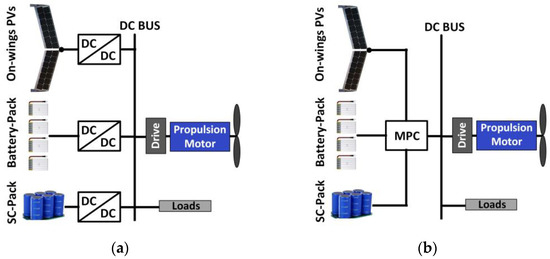
Figure 1.
Block diagram for the PV-powered UAV power system: (a) with separated converters; (b) with MPC.
This paper proposes a new MPC topology with multiple input ports for PV, battery, and supercapacitor strings that are suitable for UAV applications and investigates the potential design improvements of the power system by achieving the following benefits:
- (1)
- Fully controlled voltage step-down and step-up capability for the battery and SC was obtained at no extra cost/component size;
- (2)
- A significantly wider voltage range was available for the SC to maximize the utilization of its energy capacity and hence reduce its size without added penalties in terms of components count, current stress, and the sizes of the corresponding inductors;
- (3)
- The ability to reduce the switching current ripple in inductors by using the interleaved phase-shifted carriers modulation technique for the different input port currents.
The paper is organized into seven sections. In Section 2, the ability of the proposed converter architecture to maximize the utilization of SCs is analyzed and compared with other topologies. In Section 3, the operating principles of the proposed converter are presented. In Section 4, the proposed phase-shifted carriers interleaved modulation technique and its effect on the ripple of the inductor current was analyzed, whilst the control of the proposed converter architecture is introduced in Section 5. A detailed experimental evaluation of the proposed converter architecture is included in Section 6 and Section 7 summarizes the conclusions of this work.
2. The Proposed Converter Topology
In the HESS, the rated energy capacity (REC) of the SC is defined considering an ideal SC that can be fully discharged as:
where C and Vmax are the rated capacity and the maximum voltage of the SC, respectively. However, due to the difficulty to fully discharge the SC and the extremely high current required to handle a given power share at low voltage levels, the sizing of the SC is usually performed considering the utilized energy capacity (UEC), which is defined as:
where Vmin is the selected minimum voltage of the SC. Therefore, the utilization level of the REC of the SC is determined by its allowed maximum and minimum voltages, which are determined by the interfaced converter capabilities.
Figure 2a illustrates the effects of the selected maximum and minimum voltages (as relative to a constant bus voltage Vo) of the SC unit on the utilized energy capacity for the SC cells within the unit in one hand and the maximum current for the SC unit on the other hand. As can be observed, considering a simple boost converter for interfacing the SC limits its Vmax to be around the bus voltage (Vo), and hence the UEC can be enhanced only by minimizing Vmin, which in turn maximizes the current stress of the SC (Imax) and occurs at the selected Vmin and the current rating of the converter. Point A in the graph represents common designs of Vmax for the SC at Vo and Vmin at 0.5 Vo, which results in utilizing only 75% of the REC of the SC-cell whilst Imax is twice the load current (Io). Increasing the UEC of the SC under this topology is possible by applying more reduction in Vmin, which requires the converter to operate at a large duty cycle reducing its efficiency, and significantly increasing Imax compared to Io as depicted by point B in the graph at which 93.75% of the REC utilization can be achieved (25% increase in utilization compared point A) by setting Vmin at 0.25 Vo but at the cost of increasing Imax to four times the load current (Io). Reasonable efficiencies for the converter at such low levels of Vmin can be achieved by using other boost converter topologies such as the topologies proposed in [17,18], which can achieve a high boosting ratio at sufficient efficiency, but at the cost of the increased number of semiconductor switches and passive elements in addition to the increased current stress of the converter and SC.
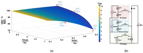
Figure 2.
(a) Variation in UEC of SC-cells with different design choices for maximum and minimum voltages of SC unit as relative to the constant bus voltage; (b) schematic diagram for the proposed MPC topology.
Implementing a buck–boost converter for interfacing the SC to the DC-bus instead of the boost converter can enable a significant increase in the UEC of the SC by allowing Vmax to be increased above Vo and hence extend the voltage range of the SC whilst maintaining Vmin at a reasonable level to limit Imax. Accordingly, designing Vmax of the SC at 2 Vo and Vmin at 0.5 Vo can result in utilizing 93.75% of the REC (as deprecated by point C in the graph), which is the same utilization level at point B but at a reduced Imax (50% compared to point B). Increasing Vmax beyond 2 Vo increases the utilization level REC but at a less significant rate (at point D, only 3.7% increase in the utilization of the REC compared to point C that corresponds to a 50% increase in Vmax). Many buck–boost converter topologies can be implemented for this purpose such as those proposed in [20,23]; however, this also in the cost of the increased number of semiconductor switches and/or passive elements.
The proposed MPC showed in Figure 2b consists of a voltage step-up (boost) PV stage integrated with two voltage step-down (buck) stages to interface with the battery and the SC, the integration of these three stages in a single MPC results in a buck/boost voltage capability for the battery and the SC ports concerning the bus voltage without the need for extra components, given that the PV boost stage switch S5 can handle the overall current. The proposed converter can be utilized in a centralized architecture based on a single converter cell as presented in this paper, or it can be utilized in modular architectures that use a number of converter cells connected in a cascade similar to the concept proposed in [35], which is suitable for higher voltages applications that are out of the scope of the paper.
In order to compare the added merits of the proposed converter architecture with other topologies targeting SC design enhancements by implementing either extreme boosting ratios or buck–boost functionality, converter parameters for the different topologies are determined and presented in Table 1 considering the same bus voltage (Vo) and appropriate.

Table 1.
Comparison between the SC-port of the proposed MPC and other converters considering the utilization of 93.75% of the rated energy capacity of the interfaced SC.
3. Operation of the Proposed Converter
The proposed converter shown in Figure 2b consists of five reverse conducting power semiconductor switches, three inductors, and a single diode (D2). The diode (D1) is a blocking diode that is normally embedded with the PV panels to prevent reverse conduction through the PV during the unavailability of the PV power and is not part of the proposed converter. VPV is the voltage of the PV array connected to the unidirectional input port of the converter, Vbatt is the voltage of the battery connected to one of the bidirectional input ports, and VSC is the voltage of the SC connected to the other bidirectional input port.
The possible operation modes of the proposed MPC as illustrated in Figure 3 are:
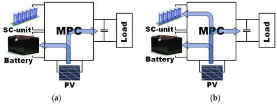
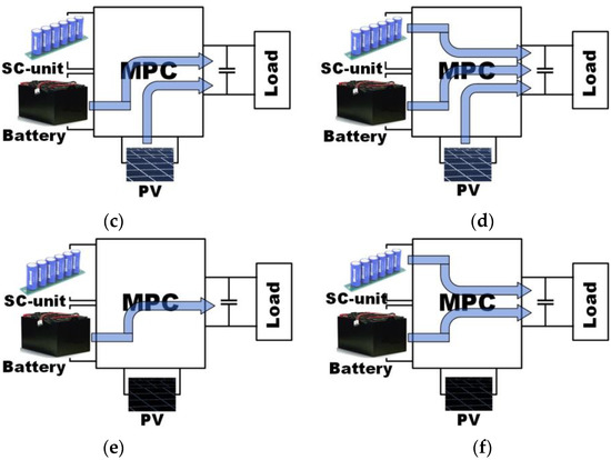
Figure 3.
Possible operation modes of the MPC: (a) SIDO mode; (b) SITO mode; (c) DISO-I mode; (d) TISO mode; (e) SISO mode and (f) DISO-II mode.
- Single input–double output (SIDO) mode (Figure 3a): where the PV supplies the required load power whilst any excess is charging the battery;
- Single input–triple output (SITO) mode (Figure 3b): where a significant amount of power is produced by the PV that can supply the load power, and due to limitations of maximum charging power of the battery, all excess is stored in the SC;
- Double input–single output mode-I (DISO-I) (Figure 3c): where the PV is unable to supply the load power, and any deficit is provided by the battery, where the load is not excessive (medium power peaks);
- Triple input–single output (TISO) mode (Figure 3d): where the PV, the battery, and the SC are supplying the load power during high power peaks, which exceed the available PV power and the battery discharge power capability;
- Single input–single output (SISO) mode (Figure 3e): where the battery provides power for supplying the load during the unavailability of the PV power;
- Double input–single output mode-II (DISO-II) (Figure 3f): where both the battery and the SC provide power for supplying the load during significant load power peaks that happen during the unavailability of PV power.
In order to simplify the analysis of the converter, continuous conduction mode (CCM) is considered for all modes of operations, and the power MOSFETs and diodes are assumed to be ideal.
3.1. Operation Principle during the SIDO Mode
The typical waveforms and current paths of the converter under SIDO mode are shown in Figure 4 and Figure 5, assuming the SC is completely charged and its voltage is higher than VO. The steps of operation during this mode can be described as follow:
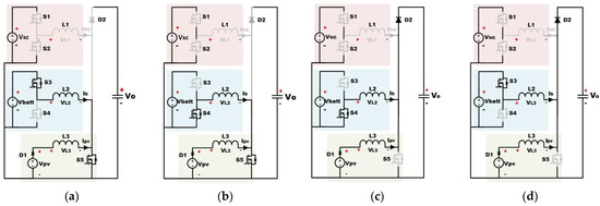
Figure 4.
Illustration of the current paths (black lines and gray lines indicate the activated and deactivated paths, respectively) during the different steps of operation of SIDO mode: (a) Step I, (b) Step II, (c) Step III, and (d) Step IV.
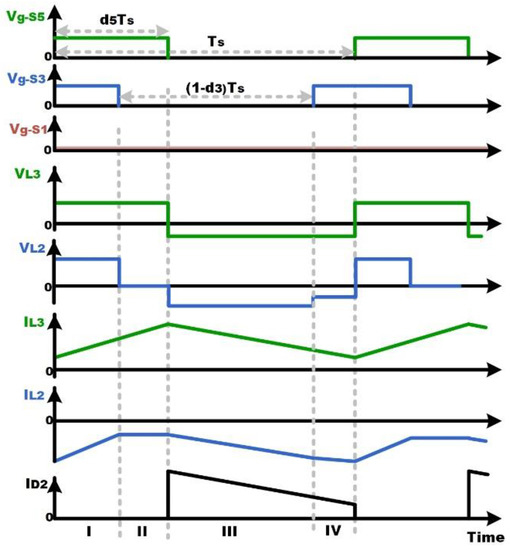
Figure 5.
Relevant voltage and current waveforms during SIDO mode.
- Step I: PV switch S5 is turned ON whilst the battery stage switch S3 is still in conduction from the previous cycle. The voltage across L3 is VPV, and the voltage across L2 is Vbatt, where the diode D2 is OFF;
- Step II: S5 is still in conduction, and D2 is still OFF when S3 is switched OFF. The voltage across the L2 becomes zero (shorted to ground via S4 and S5) whilst the voltage across L3 is still VPV;
- Step III: S5 is switched OFF, and D2 starts conduction whilst S3 is still OFF. Therefore, the voltage across the L2 is (-VO), and the voltage across L3 is (VPV-VO);
- Step IV: S5 is still OFF, and D2 is still ON when S3 is switched ON. Therefore, the voltage across the L2 is (Vbatt-VO), and the voltage across L3 is (VPV-VO).
By applying the voltage balance principle on the inductors L3, the following equation can be obtained:
Therefore
where d5 is the duty cycle of the PV stage switch S5, and for a given bus voltage VO is dependent only on PV voltage to enable extracting maximum power from the PV.
Similarly, by applying the voltage balance principle on the inductors L2, the following equation can be obtained:
Therefore
where d3 is the duty cycle of the switch S3, which, for a particular d5 and bus voltage, is dependent only on the battery voltage.
3.2. Operation Principle during the SITO Mode
The operation of the converter under the SITO mode is similar to the SIDO mode with SC in operation, as can be observed from the typical waveforms and current paths shown in Figure 6 and Figure 7.
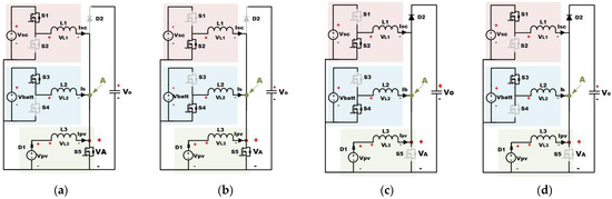
Figure 6.
Illustration of the current paths (black lines and gray lines indicate the activated and deactivated paths, respectively) during the different stages of operation of SITO mode: (a) Step I, (b) Step II, (c) Step III, and (d) Step IV.
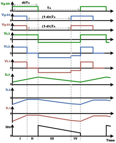
Figure 7.
Relevant voltage and current waveforms during SITO mode.
During this mode, the voltage of the SC changes significantly from Vscmin up to Vscmax. Therefore, to prevent the undesired conduction of the switch S1 through its body diode to maintain the controllability of the charging current, the average voltage at point A (shown in Figure 6) should always be less than VSC. This average voltage (VA) under this mode can be defined as:
Accordingly, to ensure the controllability of the SC current under the large variation in its voltages during charge/discharge operations, the minimum duty cycle of the switch S5 should satisfy:
where Vscmin is the minimum voltage of the SC. It can be observed that the maximum power point tracking (MPPT) function using S5 can be overridden when the required duty cycle of S5 (d5) is less than d5min. In this particular case, the switch S5 is be forced to operate with a duty cycle of d5min, causing the PV to work away from the maximum power point, which can be accepted for a short time until the SC voltage is increased to be higher than VA. The output voltage during this mode can be calculated based on (6).
3.3. Operation Principle during the DISO-I and TISO Modes
The operation of the converter during the DISO-I mode is similar to the operation during the SIDO mode, with opposite polarity for the current of L2. Moreover, the operation in TISO mode is similar to the operation during SITO, with opposite polarity for the currents of L1 and L2.
3.4. Operation Principle of the SISO Modes
During the SISO mode, as PV power is unavailable and consequently the switch S5 should be turned OFF, the battery supplies the load power through the battery stage, which represents a conventional buck converter, and by assuming that the SC voltage is at (Vscmax > VO), the output voltage can be defined as:
Accordingly, the maximum output voltage during this mode is limited to the battery voltage, compared to the previous modes of operation at which the maximum output voltage can be higher than the battery voltage. This requires the battery voltage to be designed at a voltage greater than the required output voltage to maintain the regulation of the output voltage. However, by operating the switch S5 during this mode with a duty cycle that is controlled by the output voltage control loop, the buck–boost operation of the proposed converter achieved in other modes of operation can be sustained, and regulation of the output voltage can be achieved with a battery voltage either higher or lower than the output voltage. Accordingly, to prevent the undesired conduction of the switch S3 through its body diode to maintain the controllability of battery charging current, the minimum duty cycle of the switch S5 should satisfy:
where Vbattmin is the minimum voltage of the battery at the lowest state of charge (SoC).
Typical waveforms and current paths of the converter under this mode are shown in Figure 8 and Figure 9. The output voltage during this mode can be driven by applying voltage balance on L2, same as in (5) and (6).
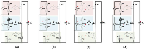
Figure 8.
Illustration of the current paths (black lines and gray lines indicate the activated and deactivated paths, respectively) during the different stages of operation of SISO mode: (a) Step I, (b) Step II, (c) Step III, and (d) Step IV.
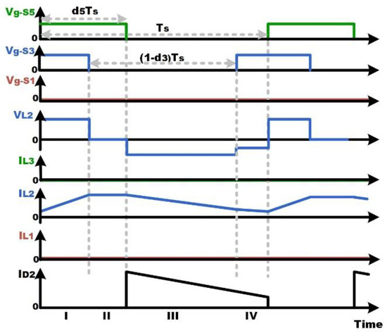
Figure 9.
Relevant voltage and current waveforms during SISO mode.
3.5. Operation Principle during the DISO-II Modes
During this mode, as the SC discharges and its voltage decreases significantly, the duty cycle of the switch S5 should satisfy (8). The output voltage during this mode can be driven by applying voltage balance on L2, same as in (5) and (6).
4. The Phase-Shifted Carriers Modulation
In order to define the size of the battery/SC stages inductors (L1, L2), the ripple currents of these inductors at the boundaries of the operating voltage range for both battery and SC need to be considered. By considering the converter output voltage of Vo, which is defined by the application, the operating voltage range of the battery can be considered as wide as from 0.75 Vo at the lowest SoC up to 1.5 Vo at the highest SoC. Accordingly, the operating voltage range of the PV array considering these conditions can be selected to be from 0.5 Vo up to 0.75 Vo. Accordingly, four operation boundary points of the battery stage inductor (L2) can be obtained, A, B, C, and D. At points A and B, the PV voltage is at its minimum; however, at point A the battery is at the highest SoC and at point B the battery is at lowest SoC. On the other hand, at points C and D, the PV voltage is at its maximum; however, at point C, the battery is at the highest SoC, and at point D, the battery is at the lowest SoC. The corresponding duty cycles for the battery and PV switches and the current ripple (∆I) of the inductor L2 at each of these boundary points at a switching frequency (fs) are listed in Table 2, and the relevant waveforms are shown in Figure 10a.
Table 2.
The peak-to-peak current ripple of the battery stage inductor (L2) at the boundaries of the operating range with/without phase-shifted carrier modulation technique.
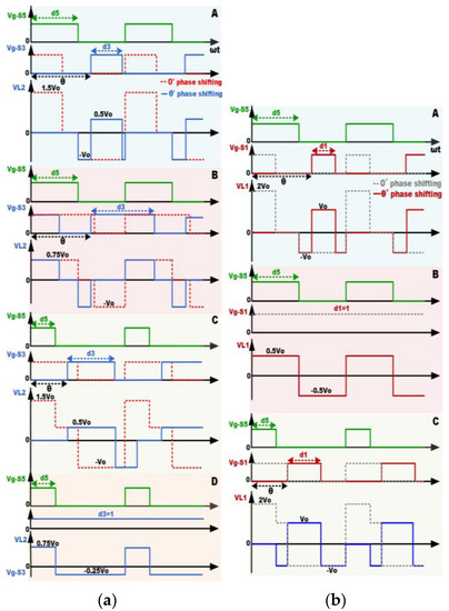
Figure 10.
(a) battery stage gating and inductor voltage waveforms at the operation boundaries (A–D); (b) SC stage gating and inductor voltage waveforms at the operation boundaries (A–C).
In order to minimize the inductor L2 current ripple, a phase-shifted carrier modulation (PSCM) technique was employed by adopting a phase-shift angle of (θο) between the PWM carriers of the switches S5 and S3 to minimize the voltage across the inductor and consequently its current ripple. The angle should be varying based on the value of the duty cycles to avoid the deadlock situation that would prevent power flow to/from the battery, which occurs when d3 = (1 − d5) and θο = 360 d5. Therefore, to achieve the minimum current ripple for L2 and avoid deadlock situations, the phase shift angle should satisfy:
From the estimated inductor current ripples under different conditions presented in Table 2, a minimum of 50% reduction in the inductor L2 current ripple was achieved by implementing the PSCM technique.
Similarly, the SC stage inductor (L1) current ripple can be reduced by implementing the PSCM technique. A minimum of 25% can be achieved as presented in Table 3, which represents the corresponding duty cycles for the SC and PV switches as well as the inductor L1 current ripple at each point, and the waveforms are shown in Figure 10b. It should be noted that when the voltage of the PV at MPP is 0.75 Vo, and Vsc is 0.5 Vo, the converter is forced to work at point B, away from MPP until SC charges and Vsc reaches 0.75 Vo, which may take a few tens of seconds, hence not affecting the PV energy harvesting.
Table 3.
The peak-to-peak current ripple of the SC stage inductor (L1) at the boundaries of the operating range with/without phase-shifted carrier modulation technique.
5. Control of the Proposed Converter
The basic idea of the control strategy for HESS is that the SC supports the high frequency/high amplitude components in the load power, which is usually estimated by a load voltage controller, and the battery supports the low-frequency power/high energy component. Therefore, a low pass filter (LPF) is usually employed to separate the slow varying average power component, which is used to derive the reference current to the battery current control loop whilst the highly dynamic power component is used to produce the reference value for the SC current control loop [36,37]. In order to further reduce the stress of the battery, an asymmetric charge/discharge current limiter was considered, as in [38]. The resulting mismatch in the battery power is added to the error component of the battery current to produce the SC reference current, which facilitates a faster and more accurate regulation of the output load voltage. The control strategy of the proposed converter prototype follows the above philosophy to accommodate the limited current capability of the high specific energy batteries used in HESS, and the resulting block diagram is shown in Figure 11, where the symbols for the state variables are indicated in the circuit diagram shown in Figure 6. First, the converter output voltage (Vo) is compared with the reference voltage (Vo_R), and the error is inputted to a PI controller. This controller estimates the current that is consumed by the load and supplied by the converter and detects any imbalance that causes deviation of load voltage from the reference. This is then used to calculate the total power (Pt) that has to be supplied by both the battery and SC whilst taking into account the available power extracted from the PV. This total power required from the energy storage is then separated into low and high-frequency components by an LPF. The reference battery power (Pb-R) is obtained by applying an asymmetric limiter to the low-frequency power component to control the charge/discharge power of the battery based on specified limits to preserve its lifetime. Given that the battery power is defined by the battery stage inductor current (Ib) multiplied by the average voltage seen at point A (shown in Figure 6), which is estimated using (7), the reference value for the battery stage inductor current Ib-R that is required to deliver this battery power is determined and passed to the battery current control loop that generates the PWM for the switches S3 and S4 accordingly. On the other hand, the SC’s reference power (PSC_R) is obtained by subtracting the reference battery power Pb-R (subject to specific battery limitations) from the total energy storage power requirement (Pt). Based on the required power from the SC and the average voltage seen at point A, the reference value for the SC stage inductor current (ISC-R) is determined and given to the SC’s current control loop, which generates the PWM for the switches S1 and S2 accordingly. The switch S5 has dual functionality: (i) to control the operating point of the PV to follow the MPPT and (ii) to ensure the controllability of the SC and battery stages’ inductors (L1, L2) is maintained, which depends on the voltage level of the SC and the battery, as described in Section 3. As the latter is a system function, therefore it has higher priority. Accordingly, the duty cycle of S5 is selected as the maximum value (that corresponds to a minimum average voltage VA) calculated based on these two functions. To clarify, considering the condition where the PV power is unavailable, the voltage of the battery (Vbatt) is at 75% of the output voltage (Vo), and the voltage of the SC (VSC) is higher than the battery voltage. Under these conditions, the calculated value for the duty cycle of the switch S5 based on MPPT function should be 0% (as there is no power available from the PV), whilst the calculated value based on the battery stage operation (based on 10) should be 25%, which is higher than the calculated value based on the SC stage according to (8) as the battery has higher voltage as mentioned above. Accordingly, the value of the duty cycle for the switch S5 should be defined by the maximum of those values, and hence S5 will operate at a 25% duty cycle. However, if for the same battery voltage, the SC voltage is 50% of the output voltage (lower than the battery voltage), then the duty cycle calculated based on the SC stage according to (8) is 50%, which is the value calculated based on battery stage according to (10), which is 25% in this case. Therefore, the switch S5 should operate by the maximum value of those two values, which is 50%.
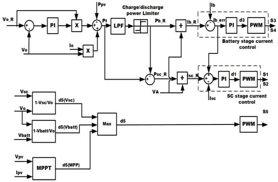
Figure 11.
The control scheme of the proposed converter.
6. Experimental Results
In order to validate the proposed converter, an experimental integrated power system setup (500 W/30 V) was implemented. The system consists of the proposed converter system that interconnects a Li-ion battery, an SC, a programmable power supply that acts as a PV emulator, and a programmable electronic load that enables the generation of customized load transients. The control scheme is implemented on a control platform that consists of TMS320C6713 DSP performing the calculations and a ProASIC®3 FPGA custom board used for the A/D conversion of voltage and current measurements and PWM signal generation. The DSP sampling and the PWM carrier switching frequency are both set to 10 kHz. The complete setup is shown in Figure 12, with the corresponding specifications listed in Table 4.
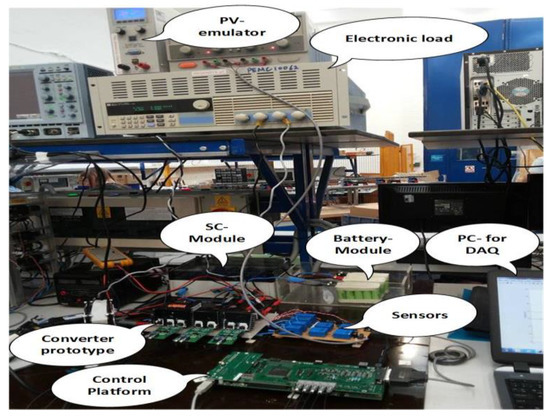
Figure 12.
Experimental setup for validating the proposed converter.
Table 4.
Specifications of the used components in the experimental setup.
The response of the converter system is evaluated under step load power transient experiments. The first test evaluates the response of the system following a large constant power peak load, as shown in Figure 13. Initially, the load consumes a constant power of 160 W, which is slightly more than the PV available power which remains constant for the duration of this experiment. As the required power from the energy storage is small, this is provided by the battery, which discharges with a low current (1 A) that is assumed to be below its current limit, and consequently, the SC current is zero, as can be seen in Figure 13a. At (t = 38 s), a large step change in the load power was applied (p = 400 W), causing the required power delivered by the energy storage to be significantly increased. As a result, the discharging current of the battery, which is the main source of stored energy, raises, reaching its limit of 5 A. The control senses this and forces the SC to contribute and support the load power peak by increasing its current to 11 A. This causes the discharge of most of SC stored energy which is seen in the SC voltage drop from 50 V to 22 V at the end of the peak power load (t = 65 s), as can be seen in Figure 13b. This test confirms the capability of the converter to maintain the output voltage(Vo) regulated at the desired value (30 V) as well as active control of the power share between the battery and the SC under the large disturbance introduced by the load power peaks. It also validates the buck–boost capability of the proposed converter at the SC port, which allowed the voltage of the SC to be changed from the higher value (50 V) that is above the Vo to the lower value (22 V) and below the Vo (which increase the utilization of SC energy capacity as discussed in Section 2) whilst maintaining the full controllability of the converter.
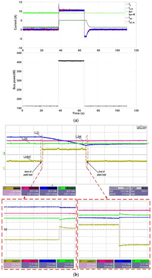
Figure 13.
Experimental results during peak power loading: (a) Battery, SC, and PV currents and bus power; (b) Battery, SC, and output voltages and output current.
The second test evaluates the performance of the proposed converter during the charging mode under imposed changes in the load. The changing scenarios are shown in Figure 14a. Initially, the load is consuming a constant power of 160 W, larger than the available PV power, and therefore, the battery discharges with a current of (≈1 A). When the load power reduces to 100 W (t = 40 s), there is extra power available from the PV, and this causes the battery to charge with 4 A. As this current is below the assumed battery current limit of 5 A, the SC contributes with charging current only during short-term transients as expected from the low/high-frequency filter effects on the reference ESS power. The SC current then reduces to zero after battery power compensates for the excess PV power. When a significant reduction in the load power occurs (t = 63 s), the battery current reaches its specified limit, and hence the SC has to absorb current during the transient period as well as absorb the excess power remaining after PV/load/battery power exchanges. This results in a noticeable rise of the SC voltage, as seen in Figure 14b. If there is excess power when the SC reaches its maximum voltage (not shown here), the control of the PV should change and move away from MPPT by capturing only the power that is consumed by the load and possibly to be absorbed by the battery. The test confirms the capability of the proposed converter to maintain the output voltage Vo regulated and perform active power share control under different variations in the loads during the charging mode of the ESS.
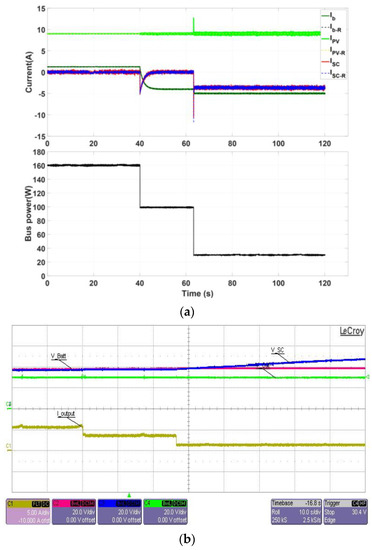
Figure 14.
Experimental results during different loading scenarios with (a) battery, SC, and output voltages and output current; (b) Battery, SC and PV currents, and bus power.
The last test evaluates the response of the converter system under the disturbances of the PV power, as shown in Figure 15. Initially, the load draws a constant power of 70 W, and the PV is supplying enough power to cover the load power and to charge the battery with 6 A. At t = 30 s, the PV source becomes unavailable; this is sensed by the control that orders the SC unit to act quickly and bridge the short-term power gap and orders the battery to start to discharge to supply the load until the PV power becomes available again at t = 85 s. As can be observed, due to the low power consumed by the load, the battery current remains below its limit (set at 10 A for this test); therefore, the SC supplies only the short-term component of the load (transient period). The test results confirm the capability of the proposed converter to maintain the regulation of the output voltage Vo under the disturbances caused by the presence/absence of the primary power source (PV) relaying on the active power share control of the ESS.
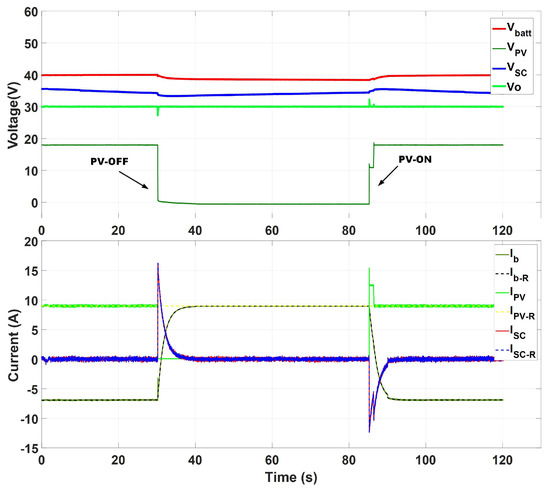
Figure 15.
Experimental results during sudden absence/presence of PV power.
A general observation that applies to all three transients is that the controller can maintain a constant output voltage with minimum disturbance (maximum of 8% of the set value).
7. Conclusions
A novel multiport converter topology for integrating a photovoltaic power source with battery–supercapacitor hybrid energy storage for PV-powered UAV applications was proposed in this paper. The proposed converter provides two ports with voltage step-down/step-up capability for interfacing the battery and supercapacitor unit and a voltage step-up port for interfacing with the PV source. The buck–boost capability of the SC port enabled a wider operating voltage range for the SC, which increases the utilization of supercapacitor energy capacity that enabled a 20% reduction in the size of the supercapacitor unit compared to the conventional approaches that utilize (voltage step-up only) topologies to interface supercapacitors. A phase-shifted carrier modulation technique was proposed, which allowed further reduction in the sizes of the inductors for the battery and supercapacitor stages. The performance of the converter was experimentally evaluated on an integrated power system prototype, which was subject to power pulses/step transients. The results showed an excellent transient response of the proposed converter and its control.
Author Contributions
Conceptualization, A.M.F.; methodology, A.M.F. and C.K.; software, A.M.F.; validation, A.M.F.; formal analysis, A.M.F. and C.K.; investigation, A.M.F. and C.K.; data curation, A.M.F.; writing—original draft preparation, A.M.F.; writing—review and editing, A.M.F., C.K. and M.S.; visualization, A.M.F.; supervision, C.K. and M.S.; funding acquisition, A.M.F. All authors have read and agreed to the published version of the manuscript.
Funding
This research was funded by the Ministry of Higher Education, Egypt, through a Ph.D. scholarship funded by the Cultural Affairs and Missions Sector.
Institutional Review Board Statement
Not applicable.
Informed Consent Statement
Not applicable.
Data Availability Statement
Not applicable.
Acknowledgments
The authors also gratefully acknowledge support from the ESTEEM project, which received funding from the Clean Sky 2 Joint Undertaking under the European Union’s Horizon 2020 research and innovation program under grant agreement No 755485.
Conflicts of Interest
The authors declare no conflict of interest.
References
- Zeng, Y.; Zhang, R.; Lim, T.J. Wireless communications with unmanned aerial vehicles: Opportunities and challenges. IEEE Commun. Mag. 2016, 54, 36–42. [Google Scholar] [CrossRef] [Green Version]
- Yanmaz, E.; Yahyanejad, S.; Rinner, B.; Hellwagner, H.; Bettstetter, C. Drone networks: Communications, coordination, and sensing. Ad Hoc Netw. 2018, 68, 1–15. [Google Scholar] [CrossRef]
- Shakhatreh, H.; Sawalmeh, A.H.; Al-Fuqaha, A.; Dou, Z.; Almaita, E.; Khalil, I.; Othman, N.S.; Khreishah, A.; Guizani, M. Unmanned Aerial Vehicles (UAVs): A Survey on Civil Applications and Key Research Challenges. IEEE Access 2019, 7, 48572–48634. [Google Scholar] [CrossRef]
- Boukoberine, M.N.; Zhou, Z.; Benbouzid, M. A critical review on unmanned aerial vehicles power supply and energy management: Solutions, strategies, and prospects. Appl. Energy 2019, 255, 113823. [Google Scholar] [CrossRef]
- D’Sa, R.; Henderson, T.; Jenson, D.; Calvert, M.; Heller, T.; Schulz, B.; Kilian, J.; Papanikolopoulos, N. Design and experiments for a transformable solar-UAV. In Proceedings of the 2017 IEEE International Conference on Robotics and Automation (ICRA), Singapore, 29 May–3 June 2017. [Google Scholar]
- Padilla, G.E.G.; Kim, K.-J.; Park, S.-H.; Yu, K.-H. Flight Path Planning of Solar-Powered UAV for Sustainable Communication Relay. IEEE Robot. Autom. Lett. 2020, 5, 6772–6779. [Google Scholar] [CrossRef]
- Dwivedi, V.S.; Giri, D.K.; Ghosh, A.K.; Kamath, G.M. Optimal Energy Utilization for a Solar-Powered Aircraft Using Sliding-Mode-Based Attitude Control. IEEE Trans. Aerosp. Electron. Syst. 2021, 57, 105–118. [Google Scholar] [CrossRef]
- Tang, S.; Zhang, L.; Guo, P.; Liu, G.; Zhang, Y.; Li, Q.; Gu, Y.; Lin, C. Processing of Monostatic SAR Data With General Configurations. IEEE Trans. Geosci. Remote Sens. 2015, 53, 6529–6546. [Google Scholar] [CrossRef]
- Xu, W.; Wang, B.; Xiang, M.; Wang, S.; Jianfeng, Y. A Novel Motion Compensation Approach Based on Symmetric Triangle Wave Interferometry for UAV SAR Imagery. IEEE Access 2020, 8, 104996–105007. [Google Scholar] [CrossRef]
- Gong, A.; MacNeill, R.; Verstraete, D.; Palmer, J.L. Analysis of a Fuel-Cell/Battery/Supercapacitor Hybrid Propulsion System for a UAV Using a Hardware-in-the-Loop Flight Simulator. In Proceedings of the 2018 AIAA/IEEE Electric Aircraft Technologies Symposium (EATS), Cincinnati, OH, USA, 12–14 July 2018. [Google Scholar]
- Zhang, X.; Liu, L.; Dai, Y.; Lu, T. Experimental investigation on the online fuzzy energy management of hybrid fuel cell/battery power system for UAVs. Int. J. Hydrogen Energy 2018, 43, 10094–10103. [Google Scholar] [CrossRef]
- Boukoberine, M.N.; Zhou, Z.; Benbouzid, M.; Donateo, T. A Frequency Separation Rule-based Power Management Strategy for a Hybrid Fuel Cell-Powered Drone. In Proceedings of the IECON 2020 the 46th Annual Conference of the IEEE Industrial Electronics Society, Singapore, 19–21 October 2020. [Google Scholar]
- Lee, B.; Kwon, S.; Park, P.; Kim, K. Active power management system for an unmanned aerial vehicle powered by solar cells, a fuel cell, and batteries. IEEE Trans. Aerosp. Electron. Syst. 2014, 50, 3167–3177. [Google Scholar] [CrossRef]
- Fares, A.; Klumpner, C.; Rashed, M. Design Considerations to Optimise Supercapacitor-based Energy Storage Systems for Aerospace Applications. In Proceedings of the 2018 IEEE International Conference on Electrical Systems for Aircraft, Railway, Ship Propulsion and Road Vehicles & International Transportation Electrification Conference (ESARS-ITEC), Nottingham, UK, 7–9 November 2018. [Google Scholar]
- Fares, A.M.; Kippke, M.; Rashed, M.; Klumpner, C.; Bozhko, S. Development of a Smart Supercapacitor Energy Storage System for Aircraft Electric Power Systems. Energies 2021, 14, 8056. [Google Scholar] [CrossRef]
- Zhang, Y.; Gao, Y.; Zhou, L.; Sumner, M. A Switched-Capacitor Bidirectional DC–DC Converter With Wide Voltage Gain Range for Electric Vehicles With Hybrid Energy Sources. IEEE Trans. Power Electron. 2018, 33, 9459–9469. [Google Scholar] [CrossRef]
- Zhang, Y.; Liu, Q.; Gao, Y.; Li, J.; Sumner, M. Hybrid Switched-Capacitor/Switched-Quasi-Z-Source Bidirectional DC–DC Converter With a Wide Voltage Gain Range for Hybrid Energy Sources EVs. IEEE Trans. Ind. Electron. 2019, 66, 2680–2690. [Google Scholar] [CrossRef]
- Elsayad, N.; Moradisizkoohi, H.; Mohammed, O.A. A New Hybrid Structure of a Bidirectional DC-DC Converter With High Conversion Ratios for Electric Vehicles. IEEE Trans. Veh. Technol. 2020, 69, 194–206. [Google Scholar] [CrossRef]
- Pires, V.F.; Foito, D.; Cordeiro, A. A DC–DC Converter With Quadratic Gain and Bidirectional Capability for Batteries/Supercapacitors. IEEE Trans. Ind. Appl. 2018, 54, 274–285. [Google Scholar] [CrossRef]
- Aharon, I.; Kuperman, A.; Shmilovitz, D. Analysis of Dual-Carrier Modulator for Bidirectional Noninverting Buck–Boost Converter. IEEE Trans. Power Electron. 2015, 30, 840–848. [Google Scholar] [CrossRef]
- Khan, M.A.; Ahmed, A.; Husain, I.; Sozer, Y.; O Badawy, M. Performance Analysis of Bidirectional DC–DC Converters for Electric Vehicles. IEEE Trans. Ind. Appl. 2015, 51, 3442–3452. [Google Scholar] [CrossRef]
- Khan, M.A.; Husain, I.; Sozer, Y. A Bidirectional DC–DC Converter With Overlapping Input and Output Voltage Ranges and Vehicle to Grid Energy Transfer Capability. IEEE J. Emerg. Sel. Top. Power Electron. 2014, 2, 507–516. [Google Scholar] [CrossRef]
- Elsayad, N.; Moradisizkoohi, H.; Mohammed, O.A. Design and Implementation of a New Transformerless Bidirectional DC–DC Converter With Wide Conversion Ratios. IEEE Trans. Ind. Electron. 2019, 66, 7067–7077. [Google Scholar] [CrossRef]
- Wu, H.; Zhang, J.; Xing, Y. A Family of Multiport Buck–Boost Converters Based on DC-Link-Inductors (DLIs). IEEE Trans. Power Electron. 2015, 30, 735–746. [Google Scholar] [CrossRef]
- Wu, H.; Chen, R.; Zhang, J.; Xing, Y.; Hu, H.; Ge, H. A Family of Three-Port Half-Bridge Converters for a Stand-Alone Renewable Power System. IEEE Trans. Power Electron. 2011, 26, 2697–2706. [Google Scholar] [CrossRef]
- Solero, L.; Lidozzi, A.; Pomilio, J.A. Design of multiple-input power converter for hybrid vehicles. IEEE Trans. Power Electron. 2005, 20, 1007–1016. [Google Scholar] [CrossRef]
- Sikkabut, S.; Mungporn, P.; Ekkaravarodome, C.; Bizon, N.; Tricoli, P.; Nahid-Mobarakeh, B.; Pierfederici, S.; Davat, B.; Thounthong, P. Control of High-Energy High-Power Densities Storage Devices by Li-ion Battery and Supercapacitor for Fuel Cell/Photovoltaic Hybrid Power Plant for Autonomous System Applications. IEEE Trans. Ind. Appl. 2016, 52, 4395–4407. [Google Scholar] [CrossRef] [Green Version]
- Xu, Q.; Xiao, J.; Hu, X.; Wang, P.; Lee, M.Y. A Decentralized Power Management Strategy for Hybrid Energy Storage System With Autonomous Bus Voltage Restoration and State-of-Charge Recovery. IEEE Trans. Ind. Electron. 2017, 64, 7098–7108. [Google Scholar] [CrossRef]
- Mesbahi, T.; Rizoug, N.; Khenfri, F.; Bartholomeüs, P.; Le Moigne, P. Dynamical modelling and emulation of Li-ion batteries-supercapacitors hybrid power supply for electric vehicle applications. IET Electr. Syst. Transp. 2017, 7, 161–169. [Google Scholar] [CrossRef]
- Torreglosa, J.P.; Garcia, P.; Fernández, L.M.; Jurado, F. Predictive Control for the Energy Management of a Fuel-Cell–Battery–Supercapacitor Tramway. IEEE Trans. Ind. Inform. 2014, 10, 276–285. [Google Scholar] [CrossRef]
- Camara, M.B.; Gualous, H.; Gustin, F.; Berthon, A. Design and New Control of DC/DC Converters to Share Energy Between Supercapacitors and Batteries in Hybrid Vehicles. IEEE Trans. Veh. Technol. 2008, 57, 2721–2735. [Google Scholar] [CrossRef]
- Wai, R.-J.; Chen, B.-H. High-Efficiency Dual-Input Interleaved DC–DC Converter for Reversible Power Sources. IEEE Trans. Power Electron. 2014, 29, 2903–2921. [Google Scholar] [CrossRef]
- Hintz, A.; Prasanna, U.R.; Rajashekara, K. Novel Modular Multiple-Input Bidirectional DC–DC Power Converter (MIPC) for HEV/FCV Application. IEEE Trans. Ind. Electron. 2015, 62, 3163–3172. [Google Scholar] [CrossRef]
- Lai, C.-M.; Cheng, Y.-H.; Hsieh, M.-H.; Lin, Y.-C. Development of a Bidirectional DC/DC Converter With Dual-Battery Energy Storage for Hybrid Electric Vehicle System. IEEE Trans. Veh. Technol. 2017, 67, 1036–1052. [Google Scholar] [CrossRef]
- Fares, A.M.; Klumpner, C.; Sumner, M. A Novel Modular Multiport Converter for Enhancing the Performance of Photovoltaic-Battery Based Power Systems. Appl. Sci. 2019, 9, 3948. [Google Scholar] [CrossRef] [Green Version]
- Sathishkumar, R.; Kollimalla, S.K.; Mishra, M.K. Dynamic energy management of micro grids using battery super capacitor combined storage. In Proceedings of the 2012 Annual IEEE India Conference (INDICON), Kochi, India, 7–9 December 2012. [Google Scholar]
- Zhou, H.; Bhattacharya, T.; Tran, D.; Siew, T.S.T.; Khambadkone, A. Composite Energy Storage System Involving Battery and Ultracapacitor With Dynamic Energy Management in Microgrid Applications. IEEE Trans. Power Electron. 2011, 26, 923–930. [Google Scholar] [CrossRef]
- Kollimalla, S.K.; Mishra, M.K.; Narasamma, N.L. Design and Analysis of Novel Control Strategy for Battery and Supercapacitor Storage System. IEEE Trans. Sustain. Energy 2014, 5, 1137–1144. [Google Scholar] [CrossRef]
Publisher’s Note: MDPI stays neutral with regard to jurisdictional claims in published maps and institutional affiliations. |
© 2022 by the authors. Licensee MDPI, Basel, Switzerland. This article is an open access article distributed under the terms and conditions of the Creative Commons Attribution (CC BY) license (https://creativecommons.org/licenses/by/4.0/).